Table of Contents
Advertisement
Quick Links
Advertisement
Table of Contents

Summary of Contents for Oricom TPS10
- Page 1 Operating Instructions TPS10 External Tyre Pressure Monitoring System Keep this user guide for future reference. Always retain your proof of purchase in case of warranty service. www.oricom.com.au Tutorial videos are available -oricom.com.au, select your model and scroll down to FAQ's...
- Page 2 This unit complies with all relevant Australian and New Zealand approval requirements AS/NZS 4268:2017...
-
Page 3: Table Of Contents
Sensor Battery Replacement........20 Specifications ............21 WARNINGS ............. 22 Express Warranty (Australia)........24 Need Help? If you need assistance setting up or using your Oricom product now or in the future, call Oricom Support. Australia (02) 4574 8888 www.oricom.com.au Mon-Fri 8am –... -
Page 4: Pack Includes
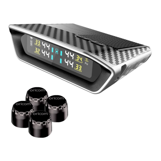
Pack Includes Pack Includes LCD Display Sensor X4 or X6 Washers X5 or X7 (1 spare) Nuts X5 or X7 (1 spare) Dustproof cover X4 or X6 Anti-slip mat X1 Sensor tool X1 Spanner X1 Ensure that these parts are stored safely. -
Page 5: Controls And Indicators
Controls and Indicators Controls and Indicators Select button SET button Solar panel Ventilation holes Micro USB input Charging status Pressure data Axles of trailer Temperature unit Pressure unit Warning indicator Temperature data Display battery indicator Tow vehicle interface Trailer interface Spare interface Note: The icon in the centre of the LCD display indicates the viewing interface. -
Page 6: Installation
Installation Display Installation Installation Position The drawing to the right indicates a suitable mounting position for your display unit. To avoid the display unit moving whilst travelling, place the anti-slip mat underneath the display unit. Powering On/Off The Display Press any button for 3 seconds to turn the display on. Press "... -
Page 7: Sensor Installation
Sensor Installation Sensor Position Sensor position Tow Vehicle Trailer Spares F.L. F.R. R.L. R.R. F.R. R.R. Note: Typical sensor position as per diagram to the left. F.L. R.L. Note: Axle B not in use Note: Depending on pack purchased you may have up to 10 sensors. Sensor Installation 1.Unscrew the valve cap. -
Page 8: Functional Testing
Functional Testing 5. Tighten up the nut to the sensor by using 6. Check for air leaks by spraying soapy water. the spanner. Note: Do not over-tighten sensors as this will effect the readings. Functional Test After Installation Once installation is complete, drive the vehicle to a speed over 25Kph to start receiving real time tyre data. -
Page 9: Alerts And Indicators
Alerts and Indicators Alerts High temperature 3 Beeps, tyre and temp flashing 3 Beeps, tyre and pressure flashing 5 Beeps, tyre and pressure flashing "LO" replace battery Sensor failure 3 Beeps, tyre and pressure flashing 5 Beeps, tyre and pressure flashing "--" displayed Display low battery 3 Beeps, tyre and pressure flashing Battery indicator flashing... -
Page 10: Settings
Note: The display automatically exits the menu when left inactive for 3 minutes. Note: Please visit our website to view tutorial videos on how to enter / exit settings, Visit www.oricom.com.au select your model and scroll down to the FAQ's section. - Page 11 Settings Pressure Unit Setting: To access the Pressure Unit setting (Bar or Psi), press the " " button to select Psi or Bar then press the " " to save and enter the next setting. Temperature Unit Setting: To access the Temperature Unit setting (degrees Celsius / Fahrenheit), press "...
- Page 12 Settings High Pressure Value Setting: • Press the " " button to set the high pressure value of the current interface. • Press " " to save and enter the next setting. Note: When more than 4 sensors are connected you can set the high pressure value for the individual interfaces (Tow vehicle / Trailer / Spare) to do this, whilst in the high pressure value setting: 1.
- Page 13 Settings Low Pressure Value Setting: • Press the " " button to set the low pressure value of the current interface. • Press " " to save and enter the next setting. Note: When more than 4 sensors are connected you can set the low pressure value for the individual interfaces (Tow vehicle / Trailer / Spare) to do this, whilst in the low pressure value setting: 1.
- Page 14 2 and 3. Press " " button once to enter the next setting. Note: Please visit our website to view tutorial videos on how to set value settings, Visit www.oricom.com.au and select model and scroll down to the FAQ's section.
- Page 15 Enabled status (default) all spare tyre sensors turned on. Disabled status spare tyre sensor turned off. Note: Please visit our website to view tutorial videos on how to disable / enable sensors, Visit www.oricom.com.au select your model and scroll down to the FAQ's section.
- Page 16 " for 4 seconds, you will hear 2 beeps confirming you have exited the menu. Note: Please visit our website to view tutorial videos on how to delete sensors, Visit www.oricom.com.au select your model and scroll down to the FAQ's section.
-
Page 17: Sensor Re-Programing
Sensor programming Sensor programming Note: Sensors in 4 and 6 packs come programmed, Additional twin sensor packs purchased will need to be programmed When programming a new sensor or a missing sensor to the display. Enter Programming Mode: Press " " button 5 times, the display will beep once to confirm you are now in sensor programming mode. - Page 18 Sensor programming - Screw the sensor to the corresponding tyre. - The pressure data will appear on the display, a beep will sound. - Press the " " button to SAVE (IMPORTANT) a beep will sound. - Press" " button to move to the next sensor and repeat the programming steps listed above.
- Page 19 "--" will appear on the screen. Once driving the tyre pressures will display automatically. NOTE: Please visit our website to view tutorial videos on how to program sensors to the control unit, Visit www.oricom.com.au select your model and scroll down to the FAQ's section.
-
Page 20: Sensor Battery Replacement
4.Unscrew the sensor cover by using the sensor tool. 5.Replace the battery. 6.Repeat steps in “Sensor Installation”. Note: Please visit our website to view tutorial videos on how to replace sensor batteries, Visit www.oricom.com.au select your model and scroll down to the FAQ's section. -
Page 21: Specifications
Specifications Sensor: Operating frequency: 433.92 ± 0.015MHz Operating voltage: 2.3~3.3V Operating temperature: -20°C~+80°C/-4°F~+176°F Pressure range: 0~7.9Bar/0~86PSI Display: Operating frequency: 433.92 ± 0.015MHz Operating voltage: 2.6~3.6V Operating current: ≤2.5mA Operating temperature: -20°C~+70°C/-4°F~+158°F Adjustable Alarm Value: High pressure value: 2.6~7.9Bar/37~86PSI Low pressure value: 0.9~3.9Bar/13~55PSI High temperature value: 70~90°C/ 158°F~ 194°F... -
Page 22: Warnings
WARNINGS 1. (TPMS) is designed for vehicles with tyre pressure up to 6.0 Bar/ 86PSI. 2. All sensors in this unit have been pre-set individually for each tyre from factory. 3. Whenever the location of a tyre is changed, the sensors must also be changed to the corresponding tyre. - Page 23 WARNINGS Troubleshooting 1. After the installation, there is no tyre data on the display * The sensors were not programmed to the display, please program the sensors * The display should show the real time tyre data automatically when the speed is over 25km/h * There is a problem with the sensor 2.
-
Page 24: Express Warranty (Australia)
In the event of a minor failure, Oricom reserves the right to choose to repair or replace the product. - Page 25 Express Warranty (Australia) component parts removed under this Express Warranty become the property of Oricom. In the unlikely event that your Oricom product has a recurring failure, Oricom may always, subject to the Competition and Consumer Act 2010, at its discretion, elect to provide you with a replacement product of its choosing that is at least equivalent to your product in performance.
- Page 26 • A completed Return Authorisation form • A copy of your Proof of Purchase (please keep your original copy) • The faulty product, including all accessories. Send the approved returns to: Oricom International Pty Ltd Locked Bag 658 South Windsor NSW 2756 Australia Please note that this Express Warranty excludes expenses incurred by you in returning any faulty product to us. You must arrange and pay any expenses...
- Page 28 Oricom Support - Australia For all product enquiries, troubleshooting or to discuss the range of Oricom products, feel free to contact Oricom or visit our website for answers to frequently asked questions. 02 4574 8888 Monday - Friday 8am –...