Samsung VP-D455 Service Manual
Digital video camcorder
Hide thumbs
Also See for VP-D455:
- Service manual (184 pages) ,
- Owner's instruction book (124 pages) ,
- Owner's instruction manual (123 pages)
Table of Contents
Advertisement
Quick Links
ELECTRONICS
This Service Manual is a property of Samsung Electronics Co .,Ltd.
Any unauthorized use of Manual can be punished under applicable
International and/or domestic law.
© Samsung Electronics Co., Ltd. FEB. 2005
Printed in Korea
AD82-00104A
DIGITAL VIDEO CAMCORDER
Chassis : Tiger
BASIC : VP-D455
Application Models
Application Area
SERVICE
DIGITAL VIDEO CAMCORDER
: VP-D451(I)/VP-D453(I)/
VP-D454(I)/VP-D455(I)/
VP-D452BI/VP-D6650I
VP-D6640I/VP-D6620I
:
XEF, XEU, XEG, XET, XEV, XEC, XSA, CDM,
XST, XEO, XEH, XEP, XEE, EAP, EUR, XEN,
HACO, TAW, TIT, COL, SEO, XSS, SED, XSH,
XSG, FES, XTL, CHN, ZAM, STS, SMR, XFA,
ITN, KNT, XSE, FPT, RAD, AND, UMG, AFR
Manual
Merit & Character regarding Product
Ultra Compact Design DVC
Use Built-in Flash Memory
(VP-D454(i)/D455(i)/D6650I Only)
Multi Memory Card Slot
(VP-D454(i)/D455(i)/D6650I Only)
Direct Print System : PictBridge ™
USB 2.0
High quality MPEG4
Digital Image Stabilizer
Real Wide mode (16:9)
Advertisement
Table of Contents

Related Manuals for Samsung VP-D455


Summary of Contents for Samsung VP-D455
- Page 1 Digital Image Stabilizer Real Wide mode (16:9) © Samsung Electronics Co., Ltd. FEB. 2005 This Service Manual is a property of Samsung Electronics Co .,Ltd. Any unauthorized use of Manual can be punished under applicable Printed in Korea International and/or domestic law.
-
Page 2: Table Of Contents
CONTENTS 1. Precautions (1-1 ~ 1-2) 2. Product Specification (2-1 ~ 2-4) 2-1 Product Specification (2-1) 2-2 Chassis Product Specification (2-2) 2-3 Accessories Supplied with Camcorder (2-3) 3. Alignment and Adjustments (3-1 ~ 3-20) 3-1 VCR Adjustment (3-1) 3-2 Camera Adjustment (3-3) 3-3 LCD Adjustment (3-7) - Page 3 CONTENTS 9. PCB Diagrams (9-1 ~ 9-10) 9-1 Main PCB (9-2) 9-2 Front PCB (9-6) 9-3 Function PCB (9-6) 9-4 CVF PCB (9-7) 9-5 CCD PCB (9-7) 9-6 Jack PCB (9-8) 9-7 LCD PCB (9-8) 9-8 Rear PCB (9-9) 10. Schematic Diagrams (10-1 ~ 10-20) 10-1 DC/DC Converter (Main PCB) (10-2)
- Page 4 CONTENTS 13. Circuit Operating Descriptions (13-1 ~ 13-12) 13-1 Digital Camcoder Summary (13-1) 13-2 Set Explanation (13-2) 13-3 H/W Function Specifications (13-6) 14. Reference Information (14-1 ~ 14-44) 14-1 Deck Operating Description (14-1) 14-2 PC INTERFACE (14-30) 14-3 Memory Card (14-34) 14-4 Camcorder Function Description (14-39)
-
Page 5: Precautions
Alternatively, wear a discharging Wrist-strap device. (Be sure to remove it prior to applying power--this is an electric shock precaution.) Samsung Electronics... - Page 6 Always inspect for pinched, out- of-place, or frayed wiring. Do not change the spacing between components and the printed circuit board. Check the AC power cord for damage. Make sure that leads and components do not touch thermally hot parts. Samsung Electronics...
-
Page 7: Product Specification (2-1 ~ 2-4)
Height 74.5 mm(2.93 inches), Length 102 mm(4.02 inches), Width 54mm(2.13 inches) Weight 360g(0.793lb) (Except for Lithium Ion Battery Pack and tape) Internal MIC Omni-directional stereo microphone Remote control Indoors: greater than 15m(49ft) (straight line), (VP-D453(i)/D454(i)/ Outdoors: about 5m(16.4ft) (straight line) D455(i) only) Samsung Electronics... -
Page 8: Product Specification
Multi Lang./ Batt. Ch eck/Instant On Ana log In O / X Remoc on / Acces so ry Shoe SB-LS80 Battery Pack Opt. Carryin g Case / Tape /Opt. O/Opt. S-Cable / Scart Jack Acces so ry Comme nt Samsung Electronics... -
Page 9: Accessories Supplied With Camcorder
2-3 Accessories Supplied with Camcorder Accessories Description Part No Remark Accessories Description Part No Remark Basic Basic Model standard of VP-D455/XEU AD43-00136A Model standard 1. Lithium Ion AD39-00073A of VP-D455/XEU 8. USB Cable Battery Pack (VP-D453(i), AD43-00146A VP-D454, VP-D455(i) only) - Page 10 Product Specification MEMO Samsung Electronics...
-
Page 11: Alignment And Adjustments (3-1 ~ 3-20)
Œ Connect the Power source. ´ Set the Power Switch to “PLAYER” position and Mode Switch to “TAPE” position. EASY Q Button MENU Button STOP Button MENU Selector Start/Stop Button Mode switch DISPLAY Button Power switch PB ZOOM Fig. 3-1 Samsung Electronics... - Page 12 Name Value Description SWP Position Head Switching Position Adjust Œ Get into VCR ADJUST mode. ´ Move to the VCR ADJUST address “6IF”. ˇ Play standard tape, and “Head Switching Position” will be adjusted automatically (within 5 Seconds). Samsung Electronics...
-
Page 13: Camera Adjustment
MENU Selector push (Confirm) Stores changed value in the adjustment and auto adjustment mode. MENU Selector Right (Data Up) Changes data in the adjustment state. MENU Selector Left (Data Down) EASY-Q (Mode Up) Changes mode. DISPLAY (Mode Down) Samsung Electronics... - Page 14 In order to complete the adjustment the power must be reset. This can be done by disconnecting and reconnecting the power source. EASY Q Button MENU Button STOP Button MENU Selector Start/Stop Button Mode switch DISPLAY Button Power switch PB ZOOM Fig. 3-4 Fig. 3-5 Samsung Electronics...
- Page 15 If you don’t have any chart, you can use the object which has a lot of vertical line. The OSD shows “OK” after finishing the adjustment. (The word “OK” is displayed for only a fraction of a second.) 3M ± 1cm (Be sure to maintain the distance) LENS Fig. 3-7 Samsung Electronics...
- Page 16 ˆ Press the “MENU Selector” (Confirm) to ensure that white spot on a vectorscope is moving in the middle of screen. Ø The OSD shows “OK” after finishing the adjustment. (The word “OK” is displayed for only a fraction of a second.) Samsung Electronics...
-
Page 17: Lcd Adjustment
Œ Connect the Power source. ´ Set the Power Switch to “PLAYER” position and Mode Switch to “TAPE” position. EASY Q Button MENU Button STOP Button MENU Selector Start/Stop Button Mode switch DISPLAY Button Power switch PB ZOOM Fig. 3-8 Samsung Electronics... - Page 18 Then VCR adjustment mode has been activated successfully. [STEP 3] In order to complete the adjustment the power must be reset. This can be done by disconnecting and reconnecting the power source. Fig. 3-9 Indicates current adjustment item Stored value Adjustment value Fig. 3-10 Samsung Electronics...
- Page 19 ◆ You continuously let two solder lands short until completing all adjustment (from 1] Initial Adj. to 7] VCO Adj.) and they must be opened after completing all adjustment. ◆ If two solder lands are continuously shorted, the product doesn’t work correctly. Samsung Electronics...
- Page 20 Alignment and Adjustments <Table 3-5> NTSC TV SIGNAL MODE TRANSMISSION TRANS-Reflective TRANSMISSION TRANS-Reflective 00 0 00 0 Samsung Electronics 3-10...
-
Page 21: Deck Adjustment
<Table 3-6> 2) Choose the polarity (depending on whether load- Movement of Chassis ing or unloading). Unloading 3) Supply the voltage to the Motor Loading, and set to the desired mode. Loading DC POWER SUPPLY Fig. 3-14 3-11 Samsung Electronics... - Page 22 ΠIn EJECT mode, clean the tape path system(from Pole Tension P1 through Pole Review P8, Pinch Roller and Capstan Shaft) and the Lower Drum. Using the lens tissue soaked in ethyl alcohol. Note : Make sure that no oil or grease adheres to the lens tissue. PINCH ROLLER Fig. 3-15 Samsung Electronics 3-12...
- Page 23 (Oil contaminated with dust might cause the bearings to wear out or seize.) ◆ A “drop”of oil is defined as the amount attached to the tip of a Ø 2mm stick as shown in Fig. 3-16. Fig. 3-16 3-13 Samsung Electronics...
- Page 24 Note : Check if the Arm Tension can be moved toward arrow “C” in PB mode. 3) Reassembly Œ For the removal of the Housing Ass’y refer to 4-2-2 (page 4-6). "C" ARM TENSION Œ CAP ADJUST ´ "A" "B" Fig. 3-17 Samsung Electronics 3-14...
- Page 25 Œ For the removal of the Idler Ass’y refer to 4-2-3 (page 4-7). ´ For the removal of the Housing Ass’y refer to 4-2-2 (page 4-6). REEL DISK S TABLE REEL DISK T TABLE RESTING SURFACE RESTING SURFACE CHASSIS SUB Fig. 3-19 3-15 Samsung Electronics...
- Page 26 If not flat (B or C in Fig. 3-21), do adjustments 3-4-5(b) through 3-4-5(d). INLET OUTLET NORMAL DEFECT AT INLET CNR02 DEFECT AT OUTLET Fig. 3-21 9 10 RF Signal (Pin 3 of CNR02) Head Switching (Pin 2 of CNR02) Fig. 3-20 Rear PCB (Bottom Side) P5 P6 Fig. 3-22 Samsung Electronics 3-16...
- Page 27 Capstan. (If the tape is twisted, turn P8, Fig. 3-23) ´ Set to REV mode and observe the outlet waveform of PB RF signal. (Fig. 3-24) ˇ If the outlet waveform is out-of-spec, turn P8 counterclockwise, and redo steps 1 and 2. (DEFECTIVE) (CORRECT) Fig. 3-24 3-17 Samsung Electronics...
- Page 28 If the track pitch is not uniform, do section 3-4-5(b) (Tracking adjustment) and 3-4-5(c) (P8 adjustment). ´ Set to CUE mode. Confirm that the waveform peaks still have a uniform pitch. (Fig. 3-27 B) If the track pitch is not uniform, do section 3-4-5(b) (Tracking Adjustment). a b c Fig. 3-27 Samsung Electronics 3-18...
- Page 29 ΠIn CUE and REV modes, check that the tape is not curled around the P2, P6 upper flange and P8 upper/Lower flanges. MOTOR CAPSTAN Fig. 3-28 P2 P3 FROM THE S REEL TO THE T REEL Fig. 3-29 3-19 Samsung Electronics...
- Page 30 Alignment and Adjustments MEMO Samsung Electronics 3-20...
-
Page 31: Disassembly And Reassembly
Caution : Please indicate that the connector must be detached before separating the Front-FPC Assembly ¨ REMOVE 1 SCREW (M1.7 X 3 BLK) Œ REMOVE 1 SCREW (M1.7 X 4 WHT) ´ REMOVE 1 SCREW (M1.7 X 4 WHT) Fig. 4-2 Ass’y Front Removal Samsung Electronics... - Page 32 ´ REMOVE 2 SCREWS ˆ REMOVE 4 SCREWS (M1.7 X 5 BLK) (M1.7 X 5 BLK) Caution : Please indicate that the connectors must be detached before separating the EASY.Q Assembly Fig. 4-4 Ass’y LCD & CVF/Jack Removal Samsung Electronics...
- Page 33 ´ REMOVE 2 SCREWS (M1.7 X 2 BLK) ˆ REMOVE Assy-Main, Assy-Lens, Assy-Deck ¨ REMOVE 3 SCREWS (T1.7 X 4 BLK) Caution : Please indicate that the connectors must be detached before separating the Right Assembly Fig. 4-6 Ass’y Right Removal Samsung Electronics...
- Page 34 Fig. 4-7 Ass’y Deck Removal 4-1-8 Ass’y Lens Removal ´ REMOVE Connector Caution : Please indicate that the connector must be detached before separating the Lens FPC Assembly Œ REMOVE 2 SCREWS (M1.7 X 2 BLK) Fig. 4-8 Ass’y Lens Removal Samsung Electronics...
-
Page 35: Deck
1) Set the power-supply output to approximately 3V~5V, and connect it to the Motor Loading. 2) Choose the polarity depending on whether loading or unloading. (See Table 4-1) 3) Supply the voltage to the Motor Loading. <Table 4-1> Movement of Chassis Loading Unloading DC POWER SUPPLY Fig. 4-9 Loading and Unloading Samsung Electronics... - Page 36 Œ LEVER LOCK HOUSING ASS'Y ” <DETAIL A> ARM L ’ SHAPE OF PIN Ô ¨ LEVER HOUSING ˆ SHAPE OF PIN ARM R ˝ SHAPE OF PIN Ø CAM PART ∏ CAM PART Fig. 4-10 Housing Ass’y Samsung Electronics...
- Page 37 Ass’y ´. the reverse direction of arrow. 2) Then lift the Idler Ass’y ˇ. 3) Secure the 2 Screws Œ. 2 SCREWS Œ COVER REEL ASS'Y ´ BRAKE S ˇ IDLER ASS'Y Fig. 4-11 Cover Reel Ass’y, Idler Ass’y Samsung Electronics...
- Page 38 Tension insert into the Guide Cam. ∏ ARM TENSION HOOK WASHER SLIT ˇ ¨ ARM TENSION ASS'Y SPRING TENSION Œ ˆ REEL DISK S PIN Ø SUB CHASSIS HOOK ´ Fig. 4-12 Arm Tension Ass’y, Reel Disk S Samsung Electronics...
- Page 39 Note 2 : When reassembling, confirm that pin of Arm Review insert into the Guide Cam. 2 SCREWS Œ SUB CHASSIS ASS'Y ´ ¨ PIN Ø SECURE HOLE MAIN CHASSIS ASS'Y ˇ ˆ MAIN CHASSIS RAIL Fig. 4-13 Sub Chassis Samsung Electronics...
- Page 40 2) Lift up the Reel Disk T ´. 3) Lift up the Brake T ˇ. ARM REVIEW Œ REEL DISK T ´ BRAKE T ˇ ¨ PIN ˆ PIN PIN Ø Fig. 4-14 Arm Review, Reel Disk T, Brake T Samsung Electronics 4-10...
- Page 41 3) Remove 1 Screw ¨ and then lift up the Holder FPC ˆ. HEAD TIP DRUM ˇ ¨ 1 SCREW ˆ HOLDER FPC Ø 2 BOSSES BASE DRUM ∏ ´ SPRING PLATE Œ 1 SCREW Fig. 4-15 Drum, Holder FPC Samsung Electronics 4-11...
- Page 42 3V~5V to the Motor Loading. 3 SCREWS Œ GUIDE ROLLER S ˇ ¨ GUIDE ROLLER T ´ GUIDE RAIL ASS'Y POLE BASE S ˆ POLE BASE T Ø ∏ MAIN CHASSIS Fig 4-16 Guide Rail Ass’y Samsung Electronics 4-12...
- Page 43 Main insert into Cam of Gear Cam Main. ASSEMBLE POINT (TWO ARROWS) 2 SCREWS ˆ Ø GEAR TENSION GEAR CAM MAIN ∏ ¨ MOTOR LOADING ASS'Y ´ ˇ 1 HOOK Œ PT WELDING 2 POINTS Fig. 4-17 Motor Loading, Gear Tension, Gear Cam Main Samsung Electronics 4-13...
- Page 44 ´ MOTOR CAPSTAN SLIDE MAIN ∏ ˇ WASHER SLIT Ø ARM PINCH ROLLER ¨ SPRING LEVER PINCH MAIN CHASSIS ˆ MAIN CHASSIS HOOK ” LEVER EJECT <DETAIL> Fig. 4-18 Motor Capstan, Arm Pinch Roller, Slide Main, LeverEject Samsung Electronics 4-14...
- Page 45 2) Hang the Belt Timming ˇ to the upper gear of the Gear Capstan ´ and mount the Gear Capstan ´. 3) Assemble the Washer Slit Œ. WASHER SLIT Œ ˇ BELT TIMING ´ GEAR CAPSTAN GEAR PULLY ¨ Fig. 4-19 Gear Pully, Belt Timming, Gear Capstan Samsung Electronics 4-15...
- Page 46 Disassembly and Reassembly MEMO Samsung Electronics 4-16...
-
Page 47: Exploded View And Parts List (5-1 ~ 5-20)
5-10 Mechanical Parts (Main Chassis) - - - - - - - - - - - - - - - - - - - - - - - - - - - - - 5-16 5-11 Mechanical Parts (Sub Chassis) - - - - - - - - - - - - - - - - - - - - - - - - - - - - - - 5-18 Samsung Electronics... -
Page 48: Ass'y Chassis
Exploded View and Parts List 5-1 Ass’y Chassis C050 M001 P155 W225 P001 W121 W206 C314 C310 P052 W125 FL515 P051 C201 W121 Samsung Electronics... - Page 49 BRACKET-LENS;TIGER-PJ,SUS301 1/2H,T C310 AD73-00134A RUBBER-CCD;SIPDER,SILICON,-,60,-,BL C314 AD97-09649A ASSY-CCD;-,TIGER,PAL,CCD, PAL FL515 3809-001654 FFC CABLE-FLAT;30V,80C,50mm,10P,0.5 M001 AD97-07910A ASSY-DECK;-,DD-4,ASSY P001 AD97-09590L ASSY-MAIN BOARD;TIGER-PJ,VP-D455/XE P051 AD97-09378A ASSY-LENS ZOOM;PC,SSCL,√ º«¸ 10X P052 AD29-00031A FILTER-OLPF;-,SSCL,-,-,4.5*3.4*1.60 P155 AD97-08613A ASSY-THETA2 DECK FPC;ASSY FPC,THETA W121 6002-001132 SCREW-TAPPING;BH,T0.5,+,2,M1.7,L3.0 W125 6001-001385 SCREW-MACHINE;CH,+,M1.7,L2.5,ZPC(BL...
-
Page 50: Ass'y Left
Exploded View and Parts List 5-2 Ass’y Left W112 FL433 P004 C023 P054 W113 C321 W297 C696 P157 W121 L001 W112 C697 P006 P158 C550 W113 C001 Samsung Electronics... - Page 51 ASSY-UNIT LEFT;ASSY,TIGER-PJ,- C550 AD41-00682A FPC-JACK;TIGER-PJ,REV.00,POLYESTER, C696 AD61-02202A BRACKET-GROUND JACK;TIGER,C5210R-H, C697 AD61-02217A PLATE-GROUND LEFT;TIGER-PJ,C5210R-H FL433 3809-001681 FFC CABLE-FLAT;30V,80,70mm,45P,0.5m L001 AD97-09697G ASSY-LCD;ASSY,VP-D455,PAL P004 AD97-09593A ASSY-FUNCTION BOARD;TIGER-PJ,SC-D45 P006 AD97-09596A ASSY-JACK BOARD;TIGER-PJ,SC-D455/XA P054 AD97-04289A ASSY-SPEAKER;-,D5-PJ,G-17S08-0823 P157 AD97-09696A ASSY-DUMMY LEFT;ASSY,TIGER-PJ,- P158 AD97-09724A ASSY-EASY FPC;-,TIGER,ASSY EASY FP...
-
Page 52: Ass'y Lcd
Exploded View and Parts List 5-3 Ass’y LCD W313 L013 L0533 C349 L004 C208 W118 L006 L015 L016 L011 W124 L017 W298 L014 W298 Samsung Electronics... - Page 53 Parts No. Description ; Specification Q’ty S.N.A Remark C208 AD61-12033A BRACKET-NUT;SV-D10,SECC,-,-,-,-,T0. C349 AD97-09517A ASSY-LED BL;-,THETA4-PJ,Stanley LED L004 AD97-09591A ASSY-LCD BOARD;TIGER-PJ,SC-D455/XAA L006 AD61-02028G CASE-LCD TOP;VP-D455,ABS94HB,T1.5,W L011 AD64-01200A BADGE-SAMSUNG;THETA2-PJ,AL,T1,W4.5, L013 AD61-02029A CASE-LCD BOTTOM;TIGER-PJ,ABS94HB,T1 L014 AD63-00732A COVER-HINGE TOP;TIGER-PJ,ABS94HB,T1 L015 AD63-00733A COVER-HINGE BOTTOM;TIGER-PJ,ABS94HB L016 AD97-09662A ASSY-HINGE;ASSY,TIGER-PJ,-...
-
Page 54: Ass'y Right
Exploded View and Parts List 5-4 Ass’y Right C014 C010 W241 C016 W127 C659 C018 C020 C308 C698 C210 C019 C059 W126 W126 C334 C660 C212 W118 W126 C661 Samsung Electronics... - Page 55 AD61-02047A PLATE-SPRING POWER;TIGER-PJ,SUS301 C334 AD63-00739A COVER-DC JACK;TIGER-PJ,ABS94HB,T1.0 C659 AD61-02017A BRACKET-RIGHT A;TIGER-PJ,SUS301 1/2 C660 AD61-02016A BRACKET-RIGHT B;TIGER-PJ,SUS301 1/2 C661 AD64-01348A BUTTON-S/STOP;TIGER-PJ,ABS 94HB,W7* C698 AD61-01494A SPRING ETC-LOCKER POWER;RAPIDO-PJ,S W118 6003-001291 SCREW-TAPTITE;CH,+,B,M1.4,L3.0,ZPC( W126 6003-001300 SCREW-TAPTITE;CH,+,B,M1.7,L4,ZPC(BL W127 6003-001292 SCREW-TAPTITE;CH(0.3),+,B,M1.7,L3,Z W241 6001-001291 SCREW-MACHINE;CH(0.5),*,-,M1.7,L4,Z Samsung Electronics...
-
Page 56: Ass'y Rear
Exploded View and Parts List 5-5 Ass’y Rear C042 P101 C208 C666 C556 C663 W222 C044 C306 P159 C664 C665 W112 W118 P009 W112 FL512 5-10 Samsung Electronics... - Page 57 PLATE-SPRING POWER;TIGER-PJ,SUS301 C334 AD63-00739A COVER-DC JACK;TIGER-PJ,ABS94HB,T1.0 C659 AD61-02017A BRACKET-RIGHT A;TIGER-PJ,SUS301 1/2 C660 AD61-02016A BRACKET-RIGHT B;TIGER-PJ,SUS301 1/2 C661 AD64-01348A BUTTON-S/STOP;TIGER-PJ,ABS 94HB,W7* C698 AD61-01494A SPRING ETC-LOCKER POWER;RAPIDO-PJ,S W118 6003-001291 SCREW-TAPTITE;CH,+,B,M1.4,L3.0,ZPC( W126 6003-001300 SCREW-TAPTITE;CH,+,B,M1.7,L4,ZPC(BL W127 6003-001292 SCREW-TAPTITE;CH(0.3),+,B,M1.7,L3,Z W241 6001-001291 SCREW-MACHINE;CH(0.5),*,-,M1.7,L4,Z Samsung Electronics 5-11...
-
Page 58: Ass'y Cvf
Parts No. Description ; Specification Q’ty S.N.A Remark C591 AD64-01371A LOCKER-CVF;TIGER-PJ,ABS94HB,BLACK,- C667 AD61-02022A CASE-CVF MAIN;TIGER-PJ,ABS94HB,T1.0 C668 AD61-02009A BRACKET-CVF STOPPER;TIGER-PJ,SUS301 L054 AD97-09846A ASSY-UNIT-CVF;NTSC/PAL∞¯øÎ,TIGER-PJ L0544 AD97-10050A ASSY-UNIT CVF;ASSY,TIGER-PJ,- L064 AD41-00683A FPC-CVF;TIGER-PJ,REV.00,POLYESTER,2 W118 6003-001291 SCREW-TAPTITE;CH,+,B,M1.4,L3.0,ZPC( W121 6002-001132 SCREW-TAPPING;BH,T0.5,+,2,M1.7,L3.0 W206 6001-001373 SCREW-MACHINE;PH,T0.5,+,M1.7,L3.0,B 5-12 Samsung Electronics... -
Page 59: Ass'y Case Left
5-7 Ass’y Case Left C208 C356 C208 C208 C208 C321 P091 W296 Loc. No Parts No. Description ; Specification Q’ty S.N.A Remark C208 AD61-12033A BRACKET-NUT;SV-D10,SECC,-,-,-,-,T0. C321 AD97-10049A ASSY-UNIT LEFT;ASSY,TIGER-PJ,- C356 AD97-09695A ASSY-TRIPOD;ASSY,TIGER-PJ,- P091 AD97-09715A ASSY-CASE LEFT;ASSY,TIGER-PJ,MULTI, W296 6003-001479 SCREW-TAPTITE;BH,+,B,M1.7,L4,ZN Samsung Electronics 5-13... -
Page 60: Ass'y Front
5-8 Ass’y Front P121 C669 P061 W127 C339 W127 Loc. No Parts No. Description ; Specification Q’ty S.N.A Remark C339 AD97-09727A ASSY-MIC;ASSY,TIGER-PJ,- C669 AD63-00741A COVER-JACK FRONT;TIGER-PJ,ABS94HB,T P061 AD97-09595C ASSY-FRONT BOARD;TIGER-PJ,SC-D457/X P121 AD97-09713A ASSY-CASE FRONT;ASSY,TIGER-PJ,LIGHT W127 6003-001292 SCREW-TAPTITE;CH(0.3),+,B,M1.7,L3,Z 5-14 Samsung Electronics... -
Page 61: Ass'y Housing
C347 W127 W116 Loc. No Parts No. Description ; Specification Q’ty S.N.A Remark C047 AD63-00736A COVER-HOUSING;TIGER-PJ,ABS94HB,T1.0 C049 AD64-01356A KNOB-TAPE EJECT;TIGER-PJ,ABS94HB,T1 C347 AD97-09719A ASSY-LINK HOUSING TOP;ASSY,TIGER-PJ C670 AD64-01339A INLAY-DECORTION;TIGER-PJ,PC,T1.0,W7 W116 6001-001527 SCREW-MACHINE;CH(0.3),+,M1.7,L2.0,N W119 6001-001444 SCREW-MACHINE;PH,+,M1.7,L2.0,ZPC(BL W127 6003-001292 SCREW-TAPTITE;CH(0.3),+,B,M1.7,L3,Z Samsung Electronics 5-15... -
Page 62: Mechanical Parts (Main Chassis)
Exploded View and Parts List 5-10 Mechanical Parts (Main Chassis) M019 M016 M018 W107 M020 M021 W101 W104 W106 M022 W103 M011 M013 W106 M017 M012 W105 M202 M023 M203 M024 M026 M025 M010 M014 M015 5-16 Samsung Electronics... - Page 63 M024 AD66-00069A GEAR-CAPSTAN;DD-3,DYAMID,0.4,28,-,- M025 AD97-06400A ASSY-ARM-PINCH;-,DD-4,ASSY AD97-09351A ASSY-ARM PINCH;ASSY,DD-4,Meiji M026 AD66-00219A GEAR-PULLEY;DD-4,DURACON M90-44,0.3 M202 6031-001417 WASHER-PLAIN;POLYSLIDE,-,ID0.8,D3.0 M203 6031-001430 WASHER-PLAIN;POLYSLIDER,-,ID0.8,D2. W101 6001-001575 SCREW-MACHINE;PH,+,M1.4,L3.5,ZPC(WH W103 6001-001591 SCREW-MACHINE;PH,+,M1.4,L4(1.5),ZPC W104 6001-001715 SCREW-MACHINE;BH,+,M1.4,L2.2,ZPC(BL W105 6001-001590 SCREW-MACHINE;PH,+,M1.4,L2.2,ZPC(BL W106 6009-001319 SCREW-SPECIAL;BH,+,-,M1.4,L2.6,ZPC( W107 6001-001452 SCREW-MACHINE;BH,+,-,M1.4,L2.5,ZPC( Samsung Electronics 5-17...
-
Page 64: Mechanical Parts (Sub Chassis)
Exploded View and Parts List 5-11 Mechanical Parts (Sub Chassis) M040 M041 M042 M036 W101 M031 M043 M044 M203 M039 M032 W102 M035 M037 M038 M033 M034 M030 5-18 Samsung Electronics... - Page 65 SPRING ETC-TENSION;DD-4,SUS304-WPB, M038 AD97-06402A ASSY-ARM-REVIEW;-,DD-4,ASSY M039 AD97-07213A ASSY-BRAKE-SOFT-S;-,DD-4,ASSY M040 AD97-06394A ASSY-HOUSING;SECC+ETC,DD-4,ASSY M041 AD61-01194A HOUSING-LOCK L;DD-4,DURACON M90-44D M042 AD61-01195A HOUSING-LOCK R;DD-4,DURACON M90-44 M043 AD61-01159A HOLDER-BAND;DD-4,DURACON M90-44,-,- M044 AD69-00425A BAND-TENSION;DD-4,LUMIRROR,-,-,-,WH M203 6031-001430 WASHER-PLAIN;POLYSLIDER,-,ID0.8,D2. W101 6001-001575 SCREW-MACHINE;PH,+,M1.4,L3.5,ZPC(WH W102 6009-001320 SCREW-SPECIAL;BH,+,,M1.4,L1.7,ZPC(Y Samsung Electronics 5-19...
- Page 66 Exploded View and Parts List MEMO 5-20 Samsung Electronics...
-
Page 67: Electrical Parts List
2203-006048 C-CER,CHIP;100NF,10%,10V,X7R,TP,100 C511 2203-005061 C-CER,CHIP;100nF,+80-20%,16V,Y5V,10 C220 2203-006048 C-CER,CHIP;100NF,10%,10V,X7R,TP,100 C513 2203-000254 C-CER,CHIP;10nF,10%,16V,X7R,1005 C221 2203-000254 C-CER,CHIP;10nF,10%,16V,X7R,1005 C514 2203-000254 C-CER,CHIP;10nF,10%,16V,X7R,1005 C222 2203-006006 C-CER,CHIP;0.005NF,°æ0.25PF,50V,C0G C515 2203-006048 C-CER,CHIP;100NF,10%,10V,X7R,TP,100 C223 2203-006006 C-CER,CHIP;0.005NF,°æ0.25PF,50V,C0G C517 2203-005061 C-CER,CHIP;100nF,+80-20%,16V,Y5V,10 Samsung Electronics This Document can not be used without Samsung’s authorization... - Page 68 2203-006048 C-CER,CHIP;100NF,10%,10V,X7R,TP,100 CM15 2203-006048 C-CER,CHIP;100NF,10%,10V,X7R,TP,100 C716 2203-000438 C-CER,CHIP;1nF,10%,50V,X7R,1005 CM16 2203-006048 C-CER,CHIP;100NF,10%,10V,X7R,TP,100 C717 2203-000254 C-CER,CHIP;10nF,10%,16V,X7R,1005 CM17 2203-006048 C-CER,CHIP;100NF,10%,10V,X7R,TP,100 C718 2203-000254 C-CER,CHIP;10nF,10%,16V,X7R,1005 CM24 2203-006048 C-CER,CHIP;100NF,10%,10V,X7R,TP,100 C719 2203-006320 C-CER,CHIP;2200nF,10%,16V,X7R,TP,20 CM29 2203-006048 C-CER,CHIP;100NF,10%,10V,X7R,TP,100 Samsung Electronics This Document can not be used without Samsung’s authorization...
- Page 69 2203-001432 C-CER,CHIP;47nF,+80-20%,16V,Y5V,100 L717 2703-002570 INDUCTOR-SMD;33UH,20%,4040 CP306 2203-000438 C-CER,CHIP;1nF,10%,50V,X7R,1005 L719 2703-002570 INDUCTOR-SMD;33UH,20%,4040 CP307 2203-000714 C-CER,CHIP;3.3nF,10%,50V,X7R,TP,100 L722 2703-002723 INDUCTOR-SMD;22UH,10%,2012 CP33 2203-006048 C-CER,CHIP;100NF,10%,10V,X7R,TP,100 L723 2703-002724 INDUCTOR-SMD;10UH,10%,2012 CP35 2203-006048 C-CER,CHIP;100NF,10%,10V,X7R,TP,100 L724 2703-002724 INDUCTOR-SMD;10UH,10%,2012 Samsung Electronics This Document can not be used without Samsung’s authorization...
- Page 70 2007-008391 R-CHIP;6.34KOHM,1%,1/16W,DA,TP,1005 Q719 0504-001102 TR-DIGITAL;EMD3,NPN/PNP,150MW,10K/1 R2220 2007-001306 R-CHIP;150OHM,5%,1/16W,TP,1005 Q720 0501-000552 TR-SMALL SIGNAL;2SA1774-Q,PNP,150mW R2221 2007-007095 R-CHIP;390OHM,5%,1/16W,TP,1005 Q721 0501-000225 TR-SMALL SIGNAL;2SC4617,NPN,200mW,E R223 2007-000170 R-CHIP;1Mohm,5%,1/16W,TP,1005 Q722 0501-002373 TR-SMALL SIGNAL;EMX2,NPN,150MW,EMT6 R233 2007-000139 R-CHIP;220ohm,5%,1/16W,TP,1005 Samsung Electronics This Document can not be used without Samsung’s authorization...
- Page 71 2007-007310 R-CHIP;8.2KOHM,1%,1/16W,TP,1005 R5151 2007-000140 R-CHIP;1Kohm,5%,1/16W,TP,1005 R501 2007-000162 R-CHIP;100Kohm,5%,1/16W,TP,1005 R5152 2007-000138 R-CHIP;100ohm,5%,1/16W,TP,1005 R502 2007-000140 R-CHIP;1Kohm,5%,1/16W,TP,1005 R5153 2007-000138 R-CHIP;100ohm,5%,1/16W,TP,1005 R503 2007-000140 R-CHIP;1Kohm,5%,1/16W,TP,1005 R5154 2007-000162 R-CHIP;100Kohm,5%,1/16W,TP,1005 R504 2007-000140 R-CHIP;1Kohm,5%,1/16W,TP,1005 R5156 2007-000140 R-CHIP;1Kohm,5%,1/16W,TP,1005 Samsung Electronics This Document can not be used without Samsung’s authorization...
- Page 72 2007-000162 R-CHIP;100Kohm,5%,1/16W,TP,1005 R626 2007-000141 R-CHIP;2.2Kohm,5%,1/16W,TP,1005 R553 2007-000140 R-CHIP;1Kohm,5%,1/16W,TP,1005 R628 2007-000146 R-CHIP;6.8Kohm,5%,1/16W,TP,1005 R554 2007-000162 R-CHIP;100Kohm,5%,1/16W,TP,1005 R629 2007-000141 R-CHIP;2.2Kohm,5%,1/16W,TP,1005 R555 2007-000140 R-CHIP;1Kohm,5%,1/16W,TP,1005 R630 2007-000141 R-CHIP;2.2Kohm,5%,1/16W,TP,1005 R556 2007-000140 R-CHIP;1Kohm,5%,1/16W,TP,1005 R631 2007-000146 R-CHIP;6.8Kohm,5%,1/16W,TP,1005 Samsung Electronics This Document can not be used without Samsung’s authorization...
- Page 73 2007-007312 R-CHIP;20Kohm,1%,1/16W,TP,1005 RM44 2007-000171 R-CHIP;0ohm,5%,1/16W,TP,1005 R788 2007-007142 R-CHIP;10Kohm,1%,1/16W,TP,1005 RM46 2007-000171 R-CHIP;0ohm,5%,1/16W,TP,1005 R789 2007-000162 R-CHIP;100Kohm,5%,1/16W,TP,1005 RM48 2007-000162 R-CHIP;100Kohm,5%,1/16W,TP,1005 R792 2007-000171 R-CHIP;0ohm,5%,1/16W,TP,1005 RM50 2007-000171 R-CHIP;0ohm,5%,1/16W,TP,1005 R793 2007-000171 R-CHIP;0ohm,5%,1/16W,TP,1005 RM52 2007-000162 R-CHIP;100Kohm,5%,1/16W,TP,1005 Samsung Electronics This Document can not be used without Samsung’s authorization...
- Page 74 2007-000148 R-CHIP;10Kohm,5%,1/16W,TP,1005 CF15 2203-005148 C-CER,CHIP;100nF,10%,16V,X7R,TP,160 RX01 2007-000171 R-CHIP;0ohm,5%,1/16W,TP,1005 CF16 2203-000257 C-CER,CHIP;10nF,10%,50V,X7R,TP,1608 RX05 2007-000171 R-CHIP;0ohm,5%,1/16W,TP,1005 CF17 2203-000257 C-CER,CHIP;10nF,10%,50V,X7R,TP,1608 W125 6001-001385 SCREW-MACHINE;CH,+,M1.7,L2.5,ZPC(BL CF18 2203-005148 C-CER,CHIP;100nF,10%,16V,X7R,TP,160 W225 6009-001410 SCREW-SPECIAL;CH,+,-,M1.4,L4.7(2.5) CF19 2203-005148 C-CER,CHIP;100nF,10%,16V,X7R,TP,160 Samsung Electronics This Document can not be used without Samsung’s authorization...
- Page 75 R-CHIP;0ohm,5%,1/10W,TP,1608 L052 AD97-09592A ASSY-CVF BOARD;TIGER-PJ,SC-D455/XAA RF62 2007-000102 R-CHIP;100Kohm,5%,1/10W,TP,1608 CL01 2203-006320 C-CER,CHIP;2200nF,10%,16V,X7R,TP,20 RF65 2007-000402 R-CHIP;150ohm,5%,1/10W,TP,1608 CL02 2203-000189 C-CER,CHIP;100nF,+80-20%,25V,Y5V,TP RF66 2007-000402 R-CHIP;150ohm,5%,1/10W,TP,1608 CL03 2404-001257 C-TA,CHIP;1UF,20%,16V,-,TP,2012 RF67 2007-000402 R-CHIP;150ohm,5%,1/10W,TP,1608 CL04 2203-000189 C-CER,CHIP;100nF,+80-20%,25V,Y5V,TP Samsung Electronics This Document can not be used without Samsung’s authorization...
- Page 76 AC14-12006D IC;KA431Z,TO-92,TAPING RR13 2007-000076 R-CHIP;330ohm,5%,1/10W,TP,1608 IC51 AC14-12001K IC;KA324,-,- RR14 2007-000076 R-CHIP;330ohm,5%,1/10W,TP,1608 AC38-12001U WIRE-JUMPER(H-WRAP);1007#26,120M/M RR15 2007-000076 R-CHIP;330ohm,5%,1/10W,TP,1608 AC38-12001U WIRE-JUMPER(H-WRAP);1007#26,120M/M RR16 2007-000052 R-CHIP;10Kohm,1%,1/10W,TP,1608 2007-000029 R-CHIP;0ohm,5%,1/8W,TP,2012 RR17 2007-000122 R-CHIP;1.2Kohm,5%,1/10W,TP,1608 AC38-12001U WIRE-JUMPER(H-WRAP);1007#26,120M/M Samsung Electronics 6-10 This Document can not be used without Samsung’s authorization...
- Page 77 M205 6031-001432 WASHER-PLAIN;POLYSLIDE,M2.5,ID1.6,O VR50 2101-001049 VR-ROTARY;500ohm,-,-,- M414 AD66-00292A PULLEY-BELT-TIMING;DD-4,POLYURETHAN 0.2 SA M416 AD97-09351A ASSY-ARM PINCH;ASSY,DD-4,Meiji 0.4 SA W101 6001-001575 SCREW-MACHINE;PH,+,M1.4,L3.5,ZPC(WH W101 6001-001575 SCREW-MACHINE;PH,+,M1.4,L3.5,ZPC(WH AD59-00085A REMOCON;-,BRM-D2AE,87X52X14,DVC,20K W102 6009-001320 SCREW-SPECIAL;BH,+,,M1.4,L1.7,ZPC(Y 6-11 Samsung Electronics This Document can not be used without Samsung’s authorization...
- Page 78 SCREW-MACHINE;CH(0.5),+,-,M1.4,L3.0 W241 6001-001291 SCREW-MACHINE;CH(0.5),*,-,M1.7,L4,Z 11 SA W296 6003-001479 SCREW-TAPTITE;BH,+,-,B,M1.7,L4,NI P W297 6001-001545 SCREW-MACHINE;PH,+,-,M1.4,L3.0,ZPC( W298 6003-001508 SCREW-TAPTITE;PH,+,B,M1.4,L3,NI PLT W298 6003-001508 SCREW-TAPTITE;PH,+,B,M1.4,L3,NI PLT W300 6003-001503 SCREW-TAPTITE;PH,+,B,M1.4,L5,ZPC(BL W313 6001-001510 SCREW-MACHINE;CH,+,-,M1.7,L2.5,NI P Samsung Electronics 6-12 This Document can not be used without Samsung’s authorization...
-
Page 79: All Block Diagram
DCT/IDCT BU7806 AUDDIO IN/OUT ADC/DAC COMP PRML IC Shuffle DECOMP VIDDEO OUT LC74132W 4M DRAM Video ENC VIDDEO IN/OUT AUDIO NJM2567 S-C IN Video Decorder 10.5M DRAM S-Y IN Samsung Electronics This Document can not be used without Samsung’s authorization... -
Page 80: Ic102 Block Diagram
GAIN 5TAP ADC45 Interpolator Viterbi Filter Control PB_CLK <Coefficient> Head Blind TEST_analog DAC45 Control Function Control ADC225 DAC225 ATFout Serial Control Function Control Register refCLK System Clock PLL/VCO (45MHz) This Document can not be used without Samsung’s authorization Samsung Electronics... -
Page 81: Ic201 Block Diagram
AHB BUS GPIO(32bit) UART * 2 MPEG4 CAMERA JPEG AHB2VIDEO CODEC DMA * 4 Timer * 4 PROCESSOR CODEC BRIDGE (30FPS@VGA) AUDIO CODEC NAND (G.726) VIDEO BUS FLASH CONTROLLER Samsung Electronics This Document can not be used without Samsung’s authorization... - Page 82 AHB BUS GPIO(32bit) UART * 2 MPEG4 CAMERA JPEG AHB2VIDEO CODEC DMA * 4 Timer * 4 PROCESSOR CODEC BRIDGE (30FPS@VGA) AUDIO CODEC NAND (G.726) VIDEO BUS FLASH CONTROLLER This Document can not be used without Samsung’s authorization Samsung Electronics...
-
Page 83: Wiring Diagram
8. Wiring Diagram (VP-D454(I)/D455(I)/D6650I) MEMORY STICK (VP-D453(I)/D6620I) Samsung Electronics... - Page 84 Wiring Diagram MEMO Samsung Electronics...
- Page 85 9-8 Rear PCB - - - - - - - - - - - - - - - - - - - - - - - - - - - - - - - - - - - - - - - - - - - - - - 9-9 Samsung Electronics...
-
Page 86: Pcb Diagrams (9-1 ~ 9-10)
PCB Diagrams 9-1 Main PCB COMPONENT SIDE Samsung Electronics... - Page 87 PCB Diagrams Œ L708 ´ L704 ˇ L706 ¨ L717 ˆ L719 Samsung Electronics...
- Page 88 PCB Diagrams CONDUCTOR SIDE Fuse 1.25A / 32V Samsung Electronics...
- Page 89 PCB Diagrams Œ XM01(54MHz) ´ XM02(48MHz) Fuse 1.25A / 32V ˇ X201(24.576M) ¨ X202(41.85M) ˆ Ø X502(32.768KHz) X501(13.5MHz) Samsung Electronics...
-
Page 90: Front Pcb
PCB Diagrams 9-2 Front PCB COMPONENT SIDE CONDUCTOR SIDE 9-3 Function PCB COMPONENT SIDE CONDUCTOR SIDE Samsung Electronics... -
Page 91: Cvf Pcb
PCB Diagrams 9-4 CVF PCB COMPONENT SIDE CONDUCTOR SIDE 9-5 CCD PCB COMPONENT SIDE CONDUCTOR SIDE Samsung Electronics... -
Page 92: Jack Pcb
PCB Diagrams 9-6 Jack PCB COMPONENT SIDE CONDUCTOR SIDE 9-7 LCD PCB COMPONENT SIDE CONDUCTOR SIDE Samsung Electronics... -
Page 93: Rear Pcb
PCB Diagrams 9-8 Rear PCB COMPONENT SIDE CONDUCTOR SIDE UART_RXD UART_TXD ENVE&Head SW # Rear PCB CNR02 9Pin @ Rear PCB CNR02 7Pin ! Rear PCB CNR02 2,3Pin Samsung Electronics... - Page 94 PCB Diagrams MEMO 9-10 Samsung Electronics...
-
Page 95: Schematic Diagrams (10-1 ~ 10-20)
10-18 LCD (LCD PCB) - - - - - - - - - - - - - - - - - - - - - - - - - - - - - - - - - - - - - - - - - 10-19 Samsung Electronics 10-1 This Document can not be used without Samsung’s authorization... -
Page 96: Dc/Dc Converter (Main Pcb)
Schematic Diagrams 10-1 DC/DC Converter (Main PCB) 10-2 This Document can not be used without Samsung’s authorization Samsung Electronics... -
Page 97: Servo (Main Pcb)
Schematic Diagrams 10-2 Servo (Main PCB) Samsung Electronics 10-3 This Document can not be used without Samsung’s authorization... -
Page 98: System Control (Main Pcb)
Schematic Diagrams 10-3 System Control (Main PCB) FROM/TO TEST JIG 10-4 This Document can not be used without Samsung’s authorization Samsung Electronics... -
Page 99: Pre Amp/Prml (Main Pcb)
Schematic Diagrams 10-4 Pre Amp/PRML (Main PCB) Samsung Electronics 10-5 This Document can not be used without Samsung’s authorization... -
Page 100: Dv-1Chip (Main Pcb)
Schematic Diagrams 10-5 DV-1Chip (Main PCB) 10-6 This Document can not be used without Samsung’s authorization Samsung Electronics... -
Page 101: Video-Interface (Main Pcb)
Schematic Diagrams 10-6 Video-Interface (Main PCB) Samsung Electronics 10-7 This Document can not be used without Samsung’s authorization... -
Page 102: Audio (Main Pcb)
Schematic Diagrams 10-7 Audio (Main PCB) 10-8 This Document can not be used without Samsung’s authorization Samsung Electronics... -
Page 103: Camera Process (Main Pcb)
Schematic Diagrams 10-8 Camera Process (Main PCB) Samsung Electronics 10-9 This Document can not be used without Samsung’s authorization... -
Page 104: Dsp (Main Pcb)
Schematic Diagrams 10-9 DSP (Main PCB) 10-10 This Document can not be used without Samsung’s authorization Samsung Electronics... -
Page 105: Camera Memory 1 (Main Pcb)
Schematic Diagrams 10-10 Camera Memory 1 (Main PCB) Samsung Electronics 10-11 This Document can not be used without Samsung’s authorization... -
Page 106: Camera Memory 2 (Main Pcb)
Schematic Diagrams 10-11 Camera Memory 2 (Main PCB) 10-12 This Document can not be used without Samsung’s authorization Samsung Electronics... -
Page 107: Ccd (Ccd Pcb)
Schematic Diagrams 10-12 CCD (CCD PCB) FROM/TO CAMERA PROCESS CNP01 Samsung Electronics 10-13 This Document can not be used without Samsung’s authorization... -
Page 108: Front (Front Pcb)
Schematic Diagrams 10-13 Front (Front PCB) FROM/TO AUDIO CN601 10-14 This Document can not be used without Samsung’s authorization Samsung Electronics... -
Page 109: Jack (Jack Pcb)
Schematic Diagrams 10-14 Jack (Jack PCB) FROM/TO VIDEO INTERFACE CN302 Samsung Electronics 10-15 This Document can not be used without Samsung’s authorization... -
Page 110: Rear (Rear Pcb)
Schematic Diagrams 10-15 Rear (Rear PCB) FROM/TO DC/DC CN702 FROM/TO PRODDUCT JIG 10-16 This Document can not be used without Samsung’s authorization Samsung Electronics... -
Page 111: Function (Function Pcb)
Schematic Diagrams 10-16 Function (Function PCB) FROM/TO VIDEO INTERFACE CN301 Samsung Electronics 10-17 This Document can not be used without Samsung’s authorization... -
Page 112: Cvf (Cvf Pcb)
Schematic Diagrams 10-17 CVF (CVF PCB) FROM/TO FUNCTION CNF05 FROM/TO CVF PANEL 10-18 This Document can not be used without Samsung’s authorization Samsung Electronics... -
Page 113: Lcd (Lcd Pcb)
Schematic Diagrams 10-18 LCD (LCD PCB) Samsung Electronics 10-19 This Document can not be used without Samsung’s authorization... - Page 114 Schematic Diagrams MEMO 10-20 This Document can not be used without Samsung’s authorization Samsung Electronics...
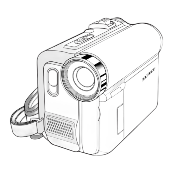
- Page 115 Lens Internal MIC USB Jack (VP-D453(i)/D454(i)/D455(i) only) LED Light (see page 49) EASY.Q button (VP-D453(i)/D454(i)/D455(i) only) (see page 40) 10. AV/S-Video Jack Remote Sensor TFT LCD Screen 11. Jack Cover (VP-D453(i)/D454(i)/D455(i) only) IEEE1394 Jack Hand Strap Hook Samsung Electronics 11-1...
- Page 116 5. DC Jack 1. Menu Selector (VOL/MF) 6. TAPE EJECT 2. MENU button 7. Zoom Lever 3. Start/Stop button 8. PHOTO button (see page 67) 4. Power Switch (CAMERA or PLAYER) 9. External MIC 5. DC Jack Cassette Door 11-2 Samsung Electronics...
- Page 117 Doing so may cause leakage, overheating, or fire. ■ Use SB-LSM80 or SB-LSM160 Battery pack only. ■ Be sure to use a recommended battery pack as described above. The batteries are available at a SAMSUNG retailer. ENGLISH Preparation Using the Lithium Ion Battery Pack ✤...
- Page 118 The continuous recording time in the operating instructions are measured using a fully charged Battery pack at 77 °F (25 °C) since the environmental temperature and conditions vary. The remaining battery time may differ from the approximate continuous recording time given in the instructions. 11-4 Samsung Electronics...
- Page 119 Operation not guaranteed for all the recommended computer environments mentioned above. ■ While transmitting data from the Camcorder to PC at strong electric field and strong magnetic field, VIDEO signal or AUDIO signal may transmit with noise. Samsung Electronics 11-5...
- Page 120 Sony Corporation. ■ ■ All other product names mentioned herein may be the trademarks or registered trademarks of their respective companies. Furthermore, “™” and “ ® ” are not mentioned in each instance in this manual. 11-6 Samsung Electronics...
-
Page 121: Troubleshooting
12. Troubleshooting Loading Emergency DECK Housing close STOP Is Loading normal? IC401~57Pin REPAIR IC501 MICOM (VS_L) 4.8V? IC401-25Pin CHECK L727 3V (VCC1) 4.5V? Changing Loading Motor Samsung Electronics 12-1... - Page 122 REPAIR IC501 MICOM IC401-16Pin 3V? CHECK IC401-5Pin is Is DRUM error OUT normal? R5108, R5107, C518, C519 VS_D 4.8V? CHECK Q702, L717 IC401 is Drum U, V, W REPAIR IC401 Waveform? DRUM U,V,W Waveform Changing Drum Motor 12-2 Samsung Electronics...
- Page 123 Troubleshooting Capstan Does Not Rotate CHECK IC501 MICOM IC401-2 3V? CHECK Is CAPSTAN error OUT IC401-44 is VS IC501-ALL CAP PWM normal? normal? CHECK Q701, L719 IC401 is CAP U,V,W CHECK IC401 normal? Changing CAP MOTOR Samsung Electronics 12-3...
- Page 124 VIDEO Y Signal Waveform normal? IC301-8, 14Pin REPAIR IC301 is Y, C signal normal? CHECK FPC VCR MAIN CHANGE THE FFC TO JACK BOARD Is VIDEO in/out CHANGE THE VIDEO Terminal normal? in/out JACK END OF REPAIR 12-4 Samsung Electronics...
- Page 125 Repair the IC501 (MICOM) IC301-8, 14Pin Is Y,C signal normal? REPAIR THE IC301 Is FPC VCR MAIN CHANGE THE FFC to JACK board normal? CHANGE THE VIDEO Is Video in/out IN/OUT JACK Terminal normal? END OF REPAIR Samsung Electronics 12-5...
- Page 126 L712, L714, L717, L719 when power is supplied? Q701~Q708-2 is the output vlotage output CHECK L701, L702 when power is supplied? Q701~Q708-1 is the output vlotage output CHANGE TR when power is supplied? REPLACE IC701 12-6 Samsung Electronics...
- Page 127 CHECK THE CONSTANT AND IC601 is output normal? WRONG SOLDERING Is Speak Connector, REPAIR THE CONNECTOR, FPC, Harness normal? FPC, HARNESS CHECK THE CONSTANT, IC201 is AUDIO VCO WRONG SOLDERING Normal? CHECK AUDIO POWER (L601, L602, L603, L604) Samsung Electronics 12-7...
- Page 128 Troubleshooting MEMO 12-8 Samsung Electronics...
-
Page 129: Circuit Operating Descriptions
5) There is no image degradation when replaying (or dubbing) recorded film Can achive clean effect without 'drop-out' detected in analog systems. Œ Unlike Hi-8, image quality is not influenced by the grade or manufacturing company of tapes. ´ Samsung Electronics 13-1... -
Page 130: Set Explanation
(14 Sync blocks) 550bits 700bits VIDEO SECTOR TRACK PAIR PRE3 VIDEO POS3 500bits (149 Sync blocks) 975bits 1550bits SUBCODE SECTOR OVERWRITE HEAD PRE4 SUBCODE POS4 MARGIN 1200bits 1200bits 1200bits 1250bits Fig. 13-2 Sector arrangement on helical track 13-2 Samsung Electronics... - Page 131 LEVEL 225 : GRAY LEVEL =128 (5) Audio Encoding mode <Table 13-2 Audio Encoding mode> Mode Channel Sampling Frequency Quantization 48K mode 48KHz 16Bits linear 44.1K mode 44.1KHz 32K mode 32KHz 32k 4ch mode 32KHz 12Bits nonlinear Samsung Electronics 13-3...
- Page 132 FP 1.5 + 0.3µs 4.7µs ± 0.2µs 0 Vpp 100% (0.3Vpp) tr, tf 250ns ± 50ns tr, tf 200ns ± 50ns - 0.15 Vpp 5.6µs ± 0.1µs 2.25µs ± 0.2µs (10cycles) - 0.3 Vpp pal timing Fig. 13-3 Video Signal 13-4 Samsung Electronics...
- Page 133 Europe Standard (EMI Part of CE) EN 55020 EN 61000-3-2 Europe Standard (EMS part of CE) EN61000-3-3 EN61000-4-3 GOST R 51515-99 Russia Standard (EMI /EMS) AS/NZS 1053 Australia Standard (EMI) Domestic electromagnetic Domestic electromagnetic wave conformity registration wave conformity registration Samsung Electronics 13-5...
-
Page 134: H/W Function Specifications
AUDIO I/F TLV990B(ICP02) S5C7376X (ICM01) DSP6 DV1 CHIP(IC201) CCD-OUT CDS/AGC/ADC GLOBAL i DIS/JPEG/MPEG4/USB uPD168103(ICP03) ZOOM/FOCUS MBM29LV160BE MOTOR DRIVER K4S283233F-EE75 TMP1962(IC501) (ICA03) 64M DSRAM MICOM 4M FLASH MEMORY ZOOM MOTOR SMC/MS FOCUS MOTOR Fig. 13-4 Camera Circuit Block Diagram 13-6 Samsung Electronics... - Page 135 BLOCK MOTOR (IC501) DV1_Chip MOTOR MICOM BLOCK LOAGDING DIRVER MOTOR AV I/F BLOCK T/S SENSOR CAMERA REEL SENSOR RS5C372A BLOCK MIC SENSOR (IC502) RTC IC RESET-IC EEPROM XC6413FY01MR 524AB0X91 (IC503) (IC505) Fig. 13-5 VCR Circuit Block Diagram Samsung Electronics 13-7...
- Page 136 DV1 CHIP MICOM (IC30 (GLOB ALi) IC-VIDEO I/F TSB41AB 1 54MHz/ IC201 (IC302) 27MHz 54MHz S5C7376X PHY. LAYER ITU-R656 (ICM01) DSP6 REC DATA PB CLK/ DATA LC74132W LA70056TB (IC101) (IC101) IC-PRML IC-PREAMP Fig. 13-6 Video Block Diagram 13-8 Samsung Electronics...
- Page 137 It can also operate the internal 1.8V regulator with an external option (pull up or pull down). In this case, it can operate at one external operating voltage of 3V. Samsung Electronics 13-9...
- Page 138 Beep sound and Speaker output signal when a key is pressed. LINE IN DV1 CHIP EXT. MIC (GLOBALi) BU7806 INT. MIC (IC601) IC201 AUDIO IF-IC SPEAKER LINE OUT TMP1962F10 (IC501) NJM2567 S-JACK (IC301) MICOM AV JACK VIDEO IF-IC Fig. 13-7 AV Interface Block Diagram 13-10 Samsung Electronics...
- Page 139 BATT.& CAPSTAN VS ADAPTER SS 3.0V VTR DD ON SS 5.0V BD983 3 KV CAM DD ON TMP1962 (IC701) (IC501) D.ERR SS 1.2V MICOM C.ERR PWM-IC LCD BL5V CCD/LCD -7.5V,-15V,+15V V.LIGHT 5.0V Fig. 13-8 DC/DC Block Diagram Samsung Electronics 13-11...
- Page 140 Circuit Operating Description MEMO 13-12 Samsung Electronics...
-
Page 141: Reference Information
¨ GEAR TENSION Ô DRUM ASS’Y ¯ BRAKE T ASS’Y ˆ POLE BASE S ASS’Y MOTOR CAPSTAN ASS’Y ˘ SWITCH MIC Ø ARM TENSION ASS’Y Ò GEAR CAPSTAN ∏ REEL DISK S ASS’Y Ú POLE BASE T ASS’Y Samsung Electronics 14-1... - Page 142 ˇ GEAR WHEEL Ô POLE BASE T ASS’Y ¨ GEAR TENSION ARM PINCH ASS’Y ˆ POLE BASE S ASS’Y Ò BELT TIMMING Ø GEAR CAM MAIN Ú SLIDE MAIN ∏ GEAR PULLY Æ LEVER EJECT ” HOLDER FPC 14-2 Samsung Electronics...
- Page 143 Idler Rotate and stop in Loading Mode LD 2 70° ~ 140.8° Capstan Rotate in Unload Mode STOP 199.89° ~ 207.85° Stop PLAY 269.3° ~ 288.5° In REC/PB/CUE/FF/PAUSE * Fig. is based Unload Mode. Common Signal 1 Signal 2 Signal 3 Fig. 14-3 Samsung Electronics 14-3...
- Page 144 2) Gear Wheel ¨ rotates. 3) Gear Tension ˆ rotates. 4) Gear Cam Main Ø rotates. MOTOR LOADING Œ GEAR WORM MOTOR ´ GEAR WORM LOADING ˇ GEAR WHEEL ¨ GEAR TENSION ˆ GEAR CAM MAIN Ø Fig. 14-4 14-4 Samsung Electronics...
- Page 145 6) Chassis Sub ∏ moved by shape of Cam ˆ in Chassis Sub ∏. LD 1 LD 2 STOP PLAY MOTOR LOADING Œ GEAR WHEEL ´ GEAR TENSION ˇ PIN Ø CAM ˆ GEAR CAM MAIN ¨ CHASSIS SUB ∏ Fig. 14-5 Samsung Electronics 14-5...
- Page 146 5) Brake S ˆ separated or contacted to Reel Disk S ¨ by LD 1 Gear Cam Main ˇ. LD 2 STOP MOTOR LOADING Œ GERA CAM MAIN ˇ REEL DISK S ¨ BRAKE S ˆ CHASSIS SUB ´ Fig. 14-6 14-6 Samsung Electronics...
- Page 147 LD 2 ◆ Brake T operation (One-Way Operation) ; Reel T rotate direction (Clock direction) STOP ; Reel t rotate direction (Count Clock direction) MOTOR LOADING Œ ¨ REEL DISK CHASSIS SUB ´ ˇ BRAKE T Fig. 14-7 Samsung Electronics 14-7...
- Page 148 Gear Tension Ø. LD 1 LD 2 STOP PLAY MOTOR LOADING Œ ARM TENSION ˇ GEAR TENSION Ø CAM CURVE B ” MAIN CHASSIS ¨ SPRING TENSION ∏ CAM CURVE A ˆ CHASSIS SUB ´ Fig. 14-8 14-8 Samsung Electronics...
- Page 149 8) Pinch Roller Ø released from shaft of Motor Capstan ∏ by spring force of Spring Lever Pinch. STOP PLAY ∏ MOTOR CAPSTAN MOTOR LOADING Œ Ø PINCH ROLLER ¨ ARM PINCH ˇ CAM CURVE A ˆ SLIDE MAIN CHASSIS SUB ´ Fig. 14-9 Samsung Electronics 14-9...
- Page 150 3) Arm Review ˆ simultaneously rotates clockwise and translates by UNLOAD Cam Curve ¨ of Chassis Main ˇ. LD 1 LD 2 STOP PLAY MOTOR LOADING Œ ˆ ARM REVIEW CHASSIS MAIN ˇ ¨ CAM CURVE CHASSIS SUB ´ Fig. 14-10 14-10 Samsung Electronics...
- Page 151 BASE DRUM STOPPER ˝ MOTOR LOADING Œ ’ GUIDE RAIL GEAR WHEEL ´ ˆ GEAR LOADING S GEAR TENSION ˇ Ø GEAR LOADING T POLE BASE S ∏ ” POLE BASE T GEAR CAM MAIN ¨ Fig. 14-11 Samsung Electronics 14-11...
- Page 152 5) Reel Disk T Ø or Reel Disk S ∏ rotates. DRUM Œ MOTOR CAPSTAN ´ GEAR CAPSTAN REEL DISK S ∏ Ø REEL DISK T ˇ BELT TIMMING GEAR IDLER ˆ ¨ GEAR PULLY Fig. 14-12 14-12 Samsung Electronics...
- Page 153 Reel-lock of Cassette tape. ˆ Chassis Sub’s Catch By Lever Lock turns on S/W Cassette-in Ø ´ COVER STOPPER Œ CATCH KEY RELEASE ˇ LEVER LOCK ¨ LEVER LOCK ¨ Ø SWITCH C-IN CHASSIS SUB CATCH ˆ Fig. 14-13 Samsung Electronics 14-13...
- Page 154 Pinch Roller rotates via Motor Loading rotates Gear Cam main and T Silder Main and reverse and then stops. operated by rotated detaches from Capstan direction and contact Shaft. Drum stops. Motor Capstan stops. Reel S, T for braking. 14-14 Samsung Electronics...
- Page 155 SWITCH MIC BASE DRUM HOLDER FPC MOTOR LOADING GEAR WHEEL MOTOR CAPSTAN GEAR TENSION GEAR CAPSTAN POLE BASE T POLE BASE S ARM PINCH ROLLER GEAR CAM MAIN BELT TIMMING SLIDE MAIN GEAR PULLY LEVER EJECT Fig. 14-14 Samsung Electronics 14-15...
- Page 156 Motor Capstan rotates forward. Gear Capstan, Belt Timing, Gear Pully, Gear Idier rotate in order. Reel S rotates. Reel T rotates. * Tape is fed by the winding operation of Motor Capstan. GEAR MODE SWITCH CAM Fig. 14-15 14-16 Samsung Electronics...
- Page 157 REEL DISK S SWITCH C-IN BRAKE S BRAKE T HOLDER FPC MOTOR LOADING MOTOR CAPSTAN GEAR WHEEL GEAR TENSION ARM PINCH ROLLER GEAR CAPSTAN BELT TIMMING GEAR CAM MAIN SLIDE MAIN GEAR PULLY LEVER EJECT Fig. 14-16 Samsung Electronics 14-17...
- Page 158 Gear Capstan, Belt Timing, Gear Pully, Gear Idler PLAY speed. rotate in order. Pinch Roller rotates 30 times faster tnan Reel T rotates 30 times faster tnan PLAY speed. PLAY speed. * This operation feeds tape 30 times faster than PLAY speed. 14-18 Samsung Electronics...
- Page 159 REEL DISK S SWITCH C-IN BRAKE S BRAKE T HOLDER FPC MOTOR LOADING MOTOR CAPSTAN GEAR WHEEL GEAR TENSION ARM PINCH ROLLER GEAR CAPSTAN BELT TIMMING SLIDE MAIN GEAR CAM MAIN GEAR PULLY LEVER EJECT Fig. 14-17 Samsung Electronics 14-19...
- Page 160 Gear Capstan, Belt Timming, Gear pully and Gear ldler rotate in order. Reel totates 30 times faster Reel S rotates 30 times faster than PLAY speed. than PLAY speed. * This operation feeds tape 30 times faster than PLAY mode. 14-20 Samsung Electronics...
- Page 161 REEL DISK S SWITCH C-IN BRAKE S BRAKE T HOLDER FPC MOTOR LOADING MOTOR CAPSTAN GEAR WHEEL GEAR TENSION ARM PINCH ROLLER GEAR CAPSTAN BELT TIMMING SLIDE MAIN GEAR CAM MAIN GEAR PULLY LEVER EJECT Fig. 14-18 Samsung Electronics 14-21...
- Page 162 Reel T stops. Reel S stops. * Drum is rotating during REC/PAUSE Push START/STOP Key. Motor Capstan rotates forward. Pinch Roller rotates. Reel T rotates. Reel S rotates. * Tape is wound to Reel T by this operation. 14-22 Samsung Electronics...
- Page 163 REEL DISK S SWITCH C-IN BRAKE S BRAKE T HOLDER FPC MOTOR LOADING MOTOR CAPSTAN GEAR WHEEL GEAR TENSION ARM PINCH ROLLER GEAR CAPSTAN BELT TIMMING SLIDE MAIN GEAR CAM MAIN GEAR PULLY LEVER EJECT Fig. 14-19 Samsung Electronics 14-23...
- Page 164 Lever Lock to release of Housing. * S/W Push is turned off. Motor Capstan stops Motor Loading stops. Housing raised (Eject completed) Motor Loading rotates forward. Lever Eject moves back by Slider Main to lock Housing. Motor Loading stops. 14-24 Samsung Electronics...
- Page 165 MOTOR CAPSTAN GEAR TENSION GEAR CAPSTAN POLE BASE T POLE BASE S ARM REVIEW ARM TENSION ARM PINCH ROLLER REEL DISK T REEL DISK S SWITCH C-IN BRAKE T BRAKE S COVER REEL SWITCH MIC Fig. 14-20 Samsung Electronics 14-25...
- Page 166 Gear Capstan, Belt Timming, Gear Pully, Gear Idler rotate in order. Reel T rotates approx. 10.5 times faster than PLAY Reel S rotates approx. 10.5 times faster mode. than PLAY mode. * Tape fed by Motor Capstan is wound up to Reel T. 14-26 Samsung Electronics...
- Page 167 Reference Information DRUM MOTOR CAPSTAN GEAR CAPSTAN REEL DISK S REEL DISK T GEAR IDLER BELT TIMMING GEAR PULLY Fig. 14-21 Samsung Electronics 14-27...
- Page 168 Gear Idler rotate in order. Reel T rotates in reverse approx. Reel S rotates in reverse approx. 9.5 times faster than PLAY mode. 9.5 times faster tnan PLAY mode. * Tape fed by Motor Capstan is wound up to Reel S. 14-28 Samsung Electronics...
- Page 169 Reference Information DRUM MOTOR CAPSTAN GEAR CAPSTAN REEL DISK S REEL DISK T GEAR IDLER BELT TIMMING GEAR PULLY Fig. 14-22 Samsung Electronics 14-29...
-
Page 170: Pc Interface
It can only be used in the Windows environment, and the electricity is restricted to 5V, 500mA. The standardization of connectors is yet to be done. Therefore, different connector manufacturers produce connectors with different looks, which makes it difficult to have connecter compatibility. 14-30 Samsung Electronics... - Page 171 Supports full-speed (12Mbps) functions Each Endpoint can be configured as: In or Out, In/Out programmable In-core Endpoint FIFOs Each can handle Bulk and/or Isochronous data transfers Endpoints interface to a microcontroller decode block Supports Suspend and Resume signaling Samsung Electronics 14-31...
- Page 172 Endpoint 0 controller only implements a control transfer. Other endpoints (1-3) can set up In/Out randomly using the setting of the In/Out programming bit. However, once the direction is set up, it cannot be changed. Also, aach endpoint can be set up as isochronous, bulk or interrupt type. 14-32 Samsung Electronics...
- Page 173 ENDPOINT INTERRUPT register would provide an endpoint along with the OUT interrupt information. On the other hand, the CSR register that is connected for each endpoint must be indexed, and can be different according the certain endpoint direction. Samsung Electronics 14-33...
-
Page 174: Memory Card
SmartMedia: 0.7mm super flat model, simple structure that doesn’t have a built-in controller MultiMedia-Card (MMC): Compact size that appeared a little later The three early standards are basically general purpose media Recent standards have developed to meet the 14-34 Samsung Electronics... - Page 175 The future mainstream will be Memory Stick (Memory Stick PRO), SD Memory Card, xD-Picture Card. Each brand is creating its own media card. CompactFlash is being widely used. MMC is mainly being used in Europe. SmartMedia usage will be reduced in the future. Samsung Electronics 14-35...
- Page 176 1) Comparison of the number of MMC and SD Memory card discs MMC had 7 discs. But SD now has 9 discs. This is in order to increase speed by changing the transfer method from serial to parallel. Fig. 14-27 14-36 Samsung Electronics...
- Page 177 The 4GB microdrive, however, needs to be in correspondence with the hardware. Current hardware adapts FAT16 to their memory card file system. Therefore, it only recognizes up to 2GB. To use the 4GB microdrive, the hardware should be compatible with FAT32. Samsung Electronics 14-37...
- Page 178 Its shape is exactly half the size of MMC. The length is a little longer than half of MMC. (The length of MMC is 32mm. The length of RS-MMC is 18mm). It can be used as a conventional MMC when the dedicated adapter is attached to the rear part. 14-38 Samsung Electronics...
-
Page 179: Camcorder Function Description
- PLAYER MODE (ON/OFF) + MEMORY MODE - M.REC MODE (ON/OFF) - M.PLAYER MODE (ON/OFF) + ON/OFF Demonstration (Setup: After ejecting the Demonstration Demonstration tape, push the menu button. Select the initial set mode and push the menu button again Samsung Electronics 14-39... - Page 180 . Displays the image as a picture negative .NEGA .MIRROR . Displays a symmetrical image, as if there is .MIRROR a mirror in the middle . Displays a color image as a black-and-white .BLK & WHT .BLK & WHT image 14-40 Samsung Electronics...
- Page 181 (TV, VCR, etc.)) .S-VIDEO IN .S-video in . High resolution image video in (allows the camcorder to copy when connecting with other equipment (TV, VCR, etc.)) Used when there is an S-video jack Samsung Electronics 14-41...
- Page 182 .DATE/TIME .DATE/TIME . When setting up on DATE/TIME, the date + OFF/DATE/TIME and time is displayed on the screen Date & Time select TV Display TV DISLAY Displays on the TV Screen(OSD) + ON/OFF 14-42 Samsung Electronics...
- Page 183 It is for 8mm. It is used when saving audio to a PC using the USB cable(video) and the audio cable DV CABLE (IEEE 1394) 1) Used for input/output by connecting a PC and camcorder (6pin-4pin cable) 2) used when connecting a camcorder to a camcorder (4pin-4pin cable) Samsung Electronics 14-43...
- Page 184 Reference Information MEMO 14-44 Samsung Electronics...
Need help?
Do you have a question about the VP-D455 and is the answer not in the manual?
Questions and answers