Table of Contents
Advertisement
Quick Links
Advertisement
Table of Contents

Related Manuals for FUTABA 7XC


Summary of Contents for FUTABA 7XC
- Page 1 NSTRUCTION ANUAL 1M23N34202...
- Page 2 INTRODUCTION Thank you for purchasing a Futaba FASSTest-2.4GHz* 7XC digital proportional R/C system. This system is extremely versatile and may be used by beginners and pros alike. In order for you to make the best use of your system and to 昀氀y safely, please read this manual carefully. If you have any dif昀椀culties while using your system, please consult the manual, our online Frequently Asked Questions (on the web pages refer- enced below), your hobby dealer.
- Page 3 NSTRUCTION ANUAL...
-
Page 4: Table Of Contents
Table Of Contents For Your Safety As Well As That Of Others ......8 Explanation Of Symbols ...............8 Receiver Mode Precautions ............8 Operation Precautions ..............9 NiMH/NiCd/LiFe Battery Handling Precautions ......10 Storage And Disposal Precautions ...........10 Other Precautions ...............11 Before Using ..............12 Features ..................12 Set Contents ................14 Transmitter T7XC .................15... - Page 5 Receiver system Change & How To Link ........35 Receivers Other Than T-FHSS ..........37 Response Mode/ SR Check ............48 Throttle Ratio Check ..............40 For Your Safety Trims Initial Set-Up ..............40 As Well As Function Map ..............42 That Of Others Menu Selection ................42 Display Menu Screen ...............42 Home Button Setting ..............43 Before...
- Page 6 Lap List ..................132 Lap timer data (lap time, average lap time) check S.BUS Servo ................133 Special function, Futaba S.BUS/S.BUS2 servo parameter / SR mode setup MC (ESC) Link ................139 Special function, Futaba ESC (MC960CR, MC851C, MC602C, MC402CR...etc.) Roll Out Chart ................148 Gear Ratio Chart ................149...
- Page 7 Telemetry System ..............151 Telemetry ..................152 Telemetry :Receiver Battery ...........153 Telemetry :The Drive Battery Voltage ........154 For Your Safety Telemetry :RPM ..............155 As Well As Telemetry :Temperature ............156 That Of Others Telemetry :The Drive Battery Electric Current ......157 Telemetry :GPS ..............159 Sensor List .................161 Sensor ..................163 Before...
-
Page 8: For Your Safety As Well As That Of Others
Under other conditions, the set will not operate, or the specified performance will not be displayed even if it operates. In addi- tion, it may cause servo trouble. Futaba will not be responsible for problems caused by the use of other than genuine Futaba parts. -
Page 9: Operation Precautions
Operation Precautions Warning Do not operate outdoors on rainy days, run through puddles of water or use when visibility is limited. Should any type of moisture (water or snow) enter any component of the system, erratic operation and loss of control may occur. -
Page 10: Nimh/Nicd/Life Battery Handling Precautions
There is the danger of colli- sion if the power is cut while running (cruising). The use of Futaba genuine NiMH or LiFe batteries is strongly recommended. -
Page 11: Other Precautions
Always use only genuine Futaba transmitters, receivers, servos, ESCs (electronic speed controls), NiMH/NiCd/LiFe batteries and other optional accessories. Futaba will not be responsible for problems caused by the use of other than genuine Futaba parts. Use the parts specified in the instruction manual and catalog. -
Page 12: Before Using
-Dual ESCs mixing for crawlers ESC at the front and rear are controlled independently. -Gyro mixing The sensitivity of Futaba car rate gyros can be adjusted from the T7XC. -Tank mixing This function is intended for vehicles such as tanks. - Page 13 This is a dedicated function which allows setting of the contents of the Link software which makes possible Futaba speed controller (ESC), MC960CR, MC950CR, MC850C, MC851C, MC602C, MC402CR, etc. variable frequency and other data changes by PC at the T7XC.
-
Page 14: Set Contents
Always use only genuine Futaba transmitters, receivers, servos, ESCs (electronic speed controls), NiMH/NiCd/LiFe batteries and other optional accessories. Futaba will not be responsible for problems caused by the use of other than Futaba genuine parts. Use the parts specifi ed in the instruction manual and catalog. -
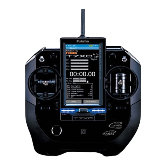
Page 15: Transmitter T7Xc
Transmitter T7XC Nomenclature *The switches, dial, and trimmers in the 昀椀 gure are shown in the initial setting position. *Please be careful not to push the switch too strongly. Digital Dial (DL1) / Switch 6 Touch Screen LCD (SW6) Switch 3 (SW3) Digital Trim5 (DT5) Switch 2 (SW2) (default dual rate) -
Page 16: Battery Replacement Method
There is the danger of collision if the power is cut while running (cruising). The use of Futaba genuine NiMH or LiFe batteries is strongly rec- ommended. -
Page 17: When Using The Optional Battery
When Using The Optional Battery When using an optional rechargeable battery, replace the battery as described below. -Always use the optional FT2F1700B , FT2F2100B or HT5F-1800B rechargeable battery. -The type of power source used must be selected through the system setting (page 180). -When the transmitter will not be used for a long time, remove the battery. -
Page 18: When Charging The Optional Battery
When Charging The Optional Battery Charging A NiMH Battery The charging time when charging the HT5F1800B battery with the optional special charger is approxi- (Example: When using the HT5F1800B with the special charger) mately 15 hours. However, when the battery has not Plug the transmitter cord of the special charger into been used for some time, repeat charging 2 or 3 times to activate the battery. -
Page 19: Power & Display Switch
Warning Never plug it into an outlet having other than the indicated voltage. Plugging the charger into the wrong outlet could result in an explosion or fi re. Do not insert and remove the charger when your hands are wet. It may cause an electric shock. -
Page 20: Display When Power Switch Is Turned On
Display When Power Switch Is Turned On The current system is displayed. Total timer or clock display (H:M) (T-FHSS SR /T-FHSS /S-FHSS /FASST) Battery voltage display When turned on by DSP switch, "Dis- Telemetry function play" is displayed Receiver -> Transmitter The reception strength is shown. -
Page 21: Steering Wheel And Throttle Trigger Operation
Steering Stick And Throttle Stick Operation (CH1: Steering stick, CH2: Throttle stick) Steering Stick Function: Turns the model right or left. Throttle Stick Function: Controls the speed of the model as well as the direction of travel - forward or reverse. Throttle stick function Steering stick function Forward... -
Page 22: Stick Lever Head Adjustment
Stick Lever Head Adjustment The length of the lever head of the steering and throttle sticks can be adjusted. Adjustment Unlock lever head "A" by turning it counterclockwise. Lever head A Adjust the head to the length best for you, then lock the heads by turning lever head "A"... -
Page 23: Mechanical Throttle Stick Stroke Adjustment
Mechanical Throttle Stick Stroke Adjustment Make this adjustment when you want to reduce the throttle stick range at the full power or brake/reverse positions. Adjustment Brake (reverse) side Make this adjustment by turning the setting screw in the fi gure with a Phillips screwdriver. - When the adjusting screw is turned counter clockwise, the stroke is reduced. -
Page 24: Neutral Adjuster Operation
Using a 1.5mm hex wrench, adjust the stick spring tension by turning the screw inside the adjusting hole. - The spring is set to the weakest tension at the factory. - When the adjusting screw is turned clockwise, the spring tension increases. Steering stick adjusting Throttle stick adjusting screw... -
Page 25: Changing To Ratchet Type Throttle Stick
Changing to Ratchet Type Throttle Stick Changing the throttle stick from the self-centering type to ratchet type that stops at an arbi- trary position. (The ratchet plate and attaching 2 x 4 mm hexagon socket button head screw in the accessory bag. ) Note: -When changing to a ratchet type always change "... - Page 26 Gently remove the rear case, without pulling excessively on the wiring. -Don’t touch internal electronic components. Wiring Remove the swing arm, spring and spring hook from the throttle stick as shown in the fi gure. - Retain these parts in case the stick is to be changed back to self-centering type later. Spring hook Swing arm Spring...
-
Page 27: Non-Telemetry Led (Telemetry Off Sign)
Non-telemetry LED (telemetry OFF sign) When the telemetry function is inhibited by race regulations, a special LED lights when the telemetry function is OFF to con昀椀 rm that the telemetry function is not operating. n is not operating. Non-telemetry LED (Lit when telemetry function is OFF) Handling the antenna and card slot and receiver About The Transmitter Antenna... -
Page 28: Receiver Terminology
Receiver Terminology R334SBS Connectors Coaxial cable Antenna Link switch/LED :CH4 servo(CH4) :CH3 servo(CH3) :Throttle servo(CH2) :Steering servo(CH1) S.BUS2 :Power /S.BUS2 connector R334SBS-E Connectors Link switch/LED :CH4 servo(CH4) :CH3 servo(CH3) :Throttle servo(CH2) :Steering servo(CH1) Antenna S.BUS2 :Power /S.BUS2 connector The receiver power supply can be connected to the S.BUS2 connector or each of CH1-4. Receiver Installation Install the receiver on the car as follows: NOTE: The operating range may reduced, depending on where the receiver and the antenna are mounted. -
Page 29: Handling A Microsd Card (Commercial Product)
Under other conditions, the set will not operate, or the specifi ed performance will not be displayed even if it operates. In addition, it may cause trouble with servos and other equipment. Futaba will not be responsible for damage, etc. caused by combination with the products of other companies. -
Page 30: Installation
Installation Receiver And Servo Connections Connect the receiver and servos as shown below. Connect and install the receiver and ser- vos in accordance with " Installation Safety Precautions " on the next page. The 昀椀gure shown below is an example. The method of connecting the motor controller to the motor and battery depends on the motor controller used. -
Page 31: Installation Safety Precautions
Connection example of S. BUS using a telemetry sensor Switch Receiver Temperature sensor RPM sensor S.BUS2 S.BUS2 Each telemetry sensor is connected Voltage sensor to the S.BUS 2 port collectively with a hub or double extention cable. Telemetry sensors (Option) Note: In SR mode, the S.BUS 2 port cannot be used other than battery input. - Page 32 Warning Receiver Vibration-proofing / Waterproofing (Car) Vibration-proof the receiver by wrapping it in foam rubber or other vibration-absorbing material and mount it with thick double-sided tape. When using the receiver holder supplied with the model kit, mount the holder to the chassis through a rubber grommet.
- Page 33 Warning Servo Throw Operate each servo over its full stroke and be sure the linkage does not bind or come loose. The continuous application of unreasonable force to a servo may cause damage and excessive battery drain. Caution! A whining noise indicates that the steering servo is improperly set.
-
Page 34: Initial Set-Up
" T-FHSS SR " , " T-FHSS " , " S-FHSS " , or " FASST " is displayed. If not displayed, there is probably an abnormality or trouble so contact a Futaba Service Center. When a screen is displayed at the " DSP " side, " Display " is displayed. -
Page 35: Receiver System Change & How To Link
Receiver system Change & How To Link First set up the receiver. Setting changes are immediately re昀氀ected. Next, the transmitter and receiver are linked and the receiver memorizes the transmitter ID number so that sig- nals from other transmitters will not be received. In addition, with the T-FHSS telemetry system, the transmitter simultaneously memorizes the receiver ID numbers so that data from other receivers will not be received. - Page 36 After set up this far is complete, when using a FASST system (R614FS/FF/FF-E) or S- FHSS system (R2104GF, R204GF-E, etc.) receiver, go to "Receiver Other Than T-FHSS" on page 37. When using a T-FHSS SR receiver (R334SBS) and T-FHSS receiver (R304SB, etc.) go to next step 3.
-
Page 37: Receivers Other Than T-Fhss
Precaution: If there are many Futaba 2.4GHz systems turned on in close proximity to your receiver might not link to your trans- mitter. In this case, even if the receiver’s LED stays solid green, unfortunately the receiver, it might not link to one of other transmitters. -
Page 38: Response Mode/ Sr Check
Response Mode/ SR Check Make sure that the response mode or SR mode setting matches the servo or other equipment to be used. Response mode is displayed. Display ON / OFF of SR mode. "Digital servo" In the case of the channel indicated as [SR], SR mode is ON. - Page 39 Under other conditions, the set will not operate, or the specifi ed performance will not be displayed even if it operates. In addition, it may cause servo trouble. Futaba will not be responsible for problems caused by the use of other than Futaba genuine parts. Use the...
-
Page 40: Throttle Ratio Check
Throttle Ratio Check -The throttle servo travel can be set to 50:50, 70:30 or 100:0 for throttle stick operation as required by the Throttle mode function (page 60). -The throttle brake operation might be close by setting it to " 100:0 " when the T7XC trans- mitter with the boat is used. - Page 41 - Steering dual rate (DT5) check At initial set-up, steering dual rate (D/R) is assigned to DT5 trim lever, at the grip of the transmitter. Operate the DT5 and check if the D/R value displayed on the screen changes. After checking D/R, set the steering dual rate to 100%. - Brake rate (DT6) check At initial setting, brake rate (Brake 1 rate) is assigned to DT6 trim lever, below DT6.
-
Page 42: Function Map
Function Map Menu Selection Use the HOME button and the LCD screen touch panel to operate the screen. In this operation manual, the HOME button is indicated by the following symbols. Display Menu Screen Push the HOME button Press and hold the HOME or tap the touch panel. -
Page 43: Home Button Setting
Home Button Setting When you push the HOME button from the home screen, it moves to the factory set menu screen. Pushing the HOME button on the menu screen or each setting screen will return you to the previous screen. Also, if you press and hold the HOME button on the Home screen, the trim lock will work and the T7XC can prohibit operations with the digital Trim DT1 to DT6 and Dial DL1 on the main unit. -
Page 44: Value Of Each Function And Changing The Set Value
Value Of Each Function And Changing The Set Value On the setting screen of each function, if you tap the item to be set, [-] [reset] [+] will be displayed at the bottom of the screen, tap the [-] [+] on the panel Set. Tap[Reset] to return to the initial value. -
Page 45: User Menu
User Menu The T7XC allows you to register your favorite functions in the user menu. You can create a different user menu for each model memory, and the user menu will also be copied by model copy (page 171). (8 types on a page, up to 48 types on 6 pages) Displaying And Editing The User Menu Screen On the user menu screen, you can display the user menu screen by tapping [User Menu] on the home screen. -
Page 46: Function List
Function List Function Name Description Of Function Page Backlight brightness setting / dimming time setting / touch panel correction Display Language setting / version information Information Sound setting (telemetry sound, alarm sound, operating sound) Sound Battery type setting / Auto power off ON / OFF Battery Date And Time Date and time setting / Displaying the time on the home screen or selecting the total timer... - Page 47 Engine Cut Twin servo mixing of the steering Steering Mixing Front and rear independent brake control for 1/5GP car, etc. Brake Mixing The sensitivity of Futaba car rate gyros can be adjusted Gyro Mixing 4-wheel steering mixing 4WS Mixing Dual ESC Front and rear ESCs mixing The CPS-1 of Futaba LED controller can be adjusted.
-
Page 48: Function Map
Function map Receiver Servo view Throttle mode (Trigger) Channel Reverse 35/50 Home screen Linkage menu-1 Sub trim End point Fail-safe Acceleration Menu screen Trim / Dial select Switch select Condition Idle-up Linkage menu-2 D/R,ATL Channel limiter Channel setting Model select Model copy Model name Model delete... - Page 49 Function map Curve(EXP) Speed Traction control A.B.S Start Engine cut Racing menu Home screen Mixing menu-1 Steering mixing Brake mixing Gyro mixing 4WS mixing Dual ESC Menu screen CPS mixing Tank mixing Program. mixing Tilt mixing Mixing menu-2 System menu-1 System menu-2 Receiver Update Display...
-
Page 50: Functions
Function Receiver This menu selects the settings matched to the receiver system used and the type of servo and the items selected at the T7XC, linking of the T7XC with the T-FHSS telemetry system, and ON/OFF. The receiver setting and selection and linking of the T7XC transmitter with T-FHSS SR, T- FHSS telemetry system receiver are described on page 37 to 39. -
Page 51: Channel Reverse
Channel Reverse This function reverses the direction of operation of the servos related to transmitter steering, throttle, channel 3, channel 4 and auxiliary channels operation. However, when the position set by trim or sub trim shifts from the center, the center becomes the opposite side. Linkage menu Channel Reverse Menu screen... -
Page 52: Sub Trim
Sub Trim Use this function to adjust the neutral position of the steering, throttle, channel 3, chan- nel 4 and auxiliary channels servos. Linkage menu Sub trim Menu screen Home screen Menu-1 Menu-2 Tap to change page. For S-FHSS (analog) system, channels 5, 6 and 7 are displayed *Sub trim adjusts the entire range of on the 2nd page. -
Page 53: End Point
End Point Use this when performing left and right end point adjustments, throttle high side/brake side operation amount adjustment, channel 3, channel 4 and auxiliary channels servos up side/ down side operation amount adjustment. - Correct the maximum steering angle for left and right steering angles when there is a difference in the turning radius due to the characteristics of the vehicle. - Page 54 Linkage menu End point Menu screen Home screen Menu-1 Menu-2 Tap to change page. Steering end point adjustment (Preparation) - Before setup of the steering end point adjustment, set the steer- ing D/R dial (initial setup: DT5) to the maximum steering angle position 100%.
- Page 55 Throttle end point adjustment (Preparation) Adjustment buttons - Use the [+] and [-] buttons to - Before setting the throttle end point adjustment, set the throttle make adjustments. ATL dial (initial setup: DT6) to the maximum throttle angle posi- - Return to the initial value by tapping the [reset] buttons.
-
Page 56: Fail-Safe/ Battery Fail-Safe
Fail-safe/ Battery Fail-safe This function sets the servo operation position when transmitter signals cannot be received by the receiver for some reason or the battery voltage has dropped. -Fail-safe mode This function moves each servo to a preset position when the receiver cannot receive the signals from the transmitter for some reason. - Page 57 Fail-safe mode selection (Preparation) - Tap the fail-safe part of the channel you want to set. The mode list appears on the Fail-safe menu screen. (Mode selection) Tap from the list and select the mode. To cancel, tap [Cancel]. (Each channel can be individually set.) Fail-safe mode Off, Hold, Fail-safe When finished with hold or off mode setting, return to the Linkage menu screen by pressing...
-
Page 58: Acceleration
Acceleration The servo will jump to the input position at its maximum possible speed. Unlike exponen- tial, which adjusts the whole throttle movement into a curve, throttle acceleration simply " jumps " away from neutral and then leaves the remaining response linear. Operation - O p e r a t i o n n e a r t h e throttle stick neutral posi-... - Page 59 Throttle acceleration adjustment Adjustment buttons (Preparation) Adjust with the [+] and [-] but- - Tap the value button of the [Forward]. Value input buttons appear tons. - Return to the initial value by on the screen and make the following adjustments: tapping the [reset] buttons.
-
Page 60: Throttle Mode (Trigger)
* The Neutral brake, which applies the brakes at the neutral position of the throttle stick, can be set. However, when using the MC950CR, MC851C, MC602C, MC402CR, or other Futaba ESC, con昀椀rm that the ESC is in the neutral position and the set is in the operation mode before setting the Neutral brake function switch to ON. - Page 61 Neutral brake "Rate" Neutral Brake function adjustment (Preparation) - Use the switch select function to the "Switch select" (page 67). When the switch is not set "A switch is not assigned" is dis- played. Tap [Switch select] to display the switch selection screen and set the switch.
-
Page 62: Servo View
Servo View Servo operation of each channel can be checked. Operation of the steering angle adjust- ment, when a mixing function was set, etc. can be easily checked. Linkage menu Servo view Menu screen Home screen Menu-1 Menu-2 For S-FHSS (analog) system, channels 1 through 7 are dis- played. -
Page 63: D/R, Atl
D/R, ATL D/R (Steering dual rate) The steering left and right servo travels are adjusted simultaneously. This setting is linked to transmitter grip trim DT5. When DT5 is assigned another function, dual rate can be ad- justed with this screen. ATL (Brake 1 rate) This function decreases the set value when the braking effect is strong and increases the set value when the braking effect is weak. -
Page 64: Trim / Dial Select
Trim / Dial Select This function allows selection of the function performed by the digital dial DL1 and digital trimmers (DT1 to DT6), step amount adjustment, and operating direction reversal. - The table in page 66 lists the functions that can be assigned to each dial and digital trim. The assigned function is also displayed on the opening screen together with the current adjustment value. - Page 65 (Changing the operation direction) Setting direction - Tap [Nor.] / [Rev.]. Tap [Nor.] or [Rev.] in the direction to set the (Nor.) Normal / (Rev.) Reverse direction. (Changing the operation step amount) Adjust button Tap the travel button of the [step]. Value in- Adjust with the [+] and [-] but- tons.
- Page 66 Set table functions (DL1/ DT1, DT2, DT3, DT4, DT5, DT6) Abbreviation used on Abbreviation displayed Function name, etc setup screen on opening screen Steering trim Steering trim Steering trim Throttle trim Throttle trim Throttle trim Channel 3 to 7 control Channel 3 to 7 control Channel 3 to 7 control (Channel 5 to 7 is for S-FHSS analog system only.) Flap...
-
Page 67: Switch Select
Switch Select This function allows selection of the function to be performed by the switches (SW1, SW2, SW3, SW4, SW5, SW6, steering stick, throttle stick) and setting of the direction, etc. of op- eration. - The table on page 69 lists the functions that can be assigned to each push switch. - The push switch SW6 is integrated with the DL1. - Page 68 Setting direction (Changing the operation direction) - Tap [Nor.] / [Rev.]. Tap [Nor.] or [Rev.] to set the direction. (Nor.) Normal / (Rev.) Reverse (Changing the the type of operation) Tap [Nor.] or [Alt.] to set the type. Setting type - Tap [Nor.] / [Alt.].
- Page 69 Set table functions (SW1/SW2/SW3/SW4/SW5/SW6) & Stick switch (SS/TS) Abbreviation used on setup screen Function name, etc Channel 3 to 7 control Operation of channel 3 to 7 (Channel 5 to 7 is for S-FHSS analog system only.) Condition 2 2nd condition function ON/OFF Program mixing (1-5) Program mixing (1-5) function ON/OFF A.B.S.
-
Page 70: Idle-Up
(ESC) will not enter the operation mode if the neutral position is not con昀椀 rmed. When using the MC950CR, MC851C, MC602C, MC402CR, or other Futaba ESC, con昀椀 rm that the ESC is in the neutral position and the set is in the operation mode before setting the idle up function switch to ON. - Page 71 Idle-up function adjustment (Preparation) - Use the switch select function to the "Switch select" (page 67). When the switch is not set "A switch is not assigned" is displayed. Tap [Switch select] to display the switch selection screen and set the switch.
-
Page 72: Channel Limiter
Channel Limiter The channel limiter function limits maximum servo movement. By superimposing mixing, the linkage can be protected by setting the limiter in case servo motion becomes unexpect- edly large. Linkage menu Channel limiter Menu screen Home screen Menu-1 Menu-2 Tap to change page. -
Page 73: Channel Setting
Channel Setting This function assigns steering or throttle to any channel. You can operate steering and throt- tle on other channels, and operate other channels in the same way as steering and throttle. Linkage menu Channel setting Menu screen Home screen Menu-1 Menu-2 How to select steering / throttle... -
Page 74: Condition
Condition Two kinds of data can be set in one model for speci昀椀 c functions only; for example, two kinds of data such as steering D/R set to 90% at normal condition and steering D/R set to 80% at second condition. This second condition can be set for each model. -The functions that can be set at each condition are displayed by condition number at the top of the menu screen. - Page 75 Condition adjustment (Preparation) - Use the switch select function to the "Switch select" (page 67). Setting (Function ON/OFF) - Tap (ON) / (OFF). Tap mode (ON) or (OFF) to select ON / OFF. "OFF" :Function OFF "ON" :Function ON Condition copy display becomes active and the condition can be used.
-
Page 76: Curve (Exp)
Curve (EXP) Steering curve This function is used to change the sensitivity of the steering servo around the neutral posi- tion. It has no effect on the maximum servo travel. Also the " Fine tune " function is which can adjust the rate for left and right separately. Steering curve Menu screen Racing menu screen... - Page 77 Steering EXP adjustment Adjustment buttons (Preparation) - Adjust with the [+] and [-] but- -Tap the curve type and select [EXP]. tons. - Return to the initial value by tapping the [reset] buttons. Tap the value button of the [EXP rate]. Value input buttons appear on the screen.
-
Page 78: Throttle Curve (Forward Side)
Throttle curve (Forward side) This function makes the throttle high side direction servo operation quicker or milder. It has no effect on the servo maximum operation amount. For the selection from among three kinds of curves (EXP/VTR/Curve) is also possible. Advice When the course conditions are good and the surface has good grip, set each curve to the plus [+] side (quick side). - Page 79 Adjustment method for EXP curve (Preparation) Adjustment buttons -Tap the curve type and select [EXP]. - Adjust with the [+] and [-] but- tons. - Return to the initial value by Tap the value button of the [EXP rate]. tapping the [reset] buttons. Value input buttons appear on the screen.
- Page 80 Adjustment buttons Adjustment method for Curve - Adjust with the [+] and [-] but- (Preparation) tons. - Return to the initial value by -Tap the curve type and select [Curve]. tapping the [reset] buttons. Curve rate Tap the value button of the [Point rate] (1 +0~+100 to 9).
-
Page 81: Brake Curve
Brake curve This function makes the throttle brake side direction servo operation quicker or milder. It has no effect on the servo maximum operation amount. For the selection from among three kinds of curves (EXP/VTR/Curve) is also possible. If Ratio is set to 100:0 with the " Throttle mode (trigger) "... -
Page 82: Speed
Speed Steering speed Quick steering operation will cause momentary understeering, loss of speed, or spinning. This function is effective in such cases. Understeering Spin Smooth cornering Without "Steering speed" With "Steering speed" Operation - This function limits the maximum speed of the steering servo. (Delay function) - The steering speed when the steering stick is operated (Turn direction) and returned (Return direction) can be inde-... - Page 83 Adjustment buttons Steering Speed adjustment - Adjust with the [+] and [-] but- tons. - Return to the initial value by tapping the [reset] buttons. ("Turn" direction delay adjustment) Speed range Tap the value button of the [Turn]. Value in- 1~100 put buttons appear on the screen.
-
Page 84: Throttle Speed
Throttle speed Sudden throttle stick operation on a slippery road only causes the wheels to spin and the vehicle cannot accelerate smoothly. Setting the throttle speed function reduces wasteful bat- tery consumption while at the same time permitting smooth, enjoyable operation. Without "Throttle speed"... - Page 85 Adjustment buttons Adjustment method for 1 Speed - Adjust with the [+] and [-] but- (Preparation) tons. - Return to the initial value by -Tap the speed mode and select [1]. tapping the [reset] buttons. Speed range ("ALL" turn direction delay adjustment) 1~100 Tap the [Turn] side of [All] value button.
- Page 86 Adjustment buttons ("Low" and "High" return direction delay adjustment) - Adjust with the [+] and [-] but- tons. Tap the [Return] side of [Low] or [High] - Return to the initial value by value button. A warning is displayed tapping the [reset] buttons. saying "Return speed will be slow.
- Page 87 Adjustment buttons ("Low", Middle", and "High" return direction delay adjustment) - Adjust with the [+] and [-] but- tons. Tap the [Return] side of [Low], [Middle] - Return to the initial value by or [High] value button. A warning is tapping the [reset] buttons.
- Page 88 A.B.S When the brakes are applied while cornering with a 4-Wheel Drive or other type of vehicle, understeer may occur. The tendency to under- steer can be eliminated and corners can be smoothly cleared by using this function. Operation - When the brakes are applied, the throttle servo will pulse inter- Without "A.B.S"...
- Page 89 - Delay Sets the delay from brake operation to ABS operation. When set to 0%, the ABS func- tion is activated without any delay. At 50%, the ABS function is activated after a delay of approximately 0.7 seconds and at 100%, the ABS function is activated after a delay of ap- proximately 1.4 seconds.
- Page 90 Adjustment buttons ("Delay" amount setup) - Adjust with the [+] and [-] but- tons. Tap the value button of the [Delay]. Value - Return to the initial value by input buttons appear on the screen. Use tapping the [reset] buttons. the [+] and [-] buttons to adjust the delay amount.
- Page 91 Adjustment buttons ("Throttle point" setup) - Adjust with the [+] and [-] but- tons. Tap the value button of the [Throttle point]. Value input but- - Return to the initial value by tons appear on the screen. Use the [+] and [-] buttons to ad- tapping the [reset] buttons.
- Page 92 Switch setting Use SW1 to SW6 to switch the " A.B.S. " function ON/OFF. See the " Switch select " function (page 67). Dial / Trim Setting The brake return amount, delay amount and cycle speed can be adjusted with digital trim DT1 to DT6 or digital dial DL1, with the "...
-
Page 93: Traction Control
Traction control Throttle stick operation with cornering on a slippery road surface is hard to get traction and smooth cornering cannot be done. By intermittently operating the operation of the throttle, you can smoothly navigate and travel on topological lines. Also, with a drift car, by in- termittently operating the motor in the high point direction, a pseudo reverberator engine sound can be reproduced. - Page 94 - Delay Set the delay from when the throttle is operated until when the traction control operation starts. When set to 0%, the traction control function works without delay. At 50%, the trac- tion control function works approximately 0.5 second later, and the traction control function works about 1.0 second later at 100%.
- Page 95 Adjustment buttons ("Delay" amount setup) - Adjust with the [+] and [-] but- tons. Tap the value button of the [Delay]. Value - Return to the initial value by input buttons appear on the screen. Use tapping the [reset] buttons. the [+] and [-] buttons to adjust the delay amount.
- Page 96 Adjustment buttons ("Throttle point" setup) - Adjust with the [+] and [-] but- tons. Tap the value button of the [Throttle point]. Value input but- - Return to the initial value by tons appear on the screen. Use the [+] and [-] buttons to ad- tapping the [reset] buttons.
-
Page 97: Start
Start If the track is slippery and you begin to moving by operation the throttle stick to full throt- tle, the car wheels will spin and the car will not accelerate smoothly. When the Start func- tion is activated, merely operating the throttle stick slowly causes the throttle servo to auto- matically switch from the set throttle position to a preset point so that the tires do not lose their grip and the car accelerates smoothly. - Page 98 Adjustment buttons ("Throttle point" setup) - Adjust with the [+] and [-] but- Tap the value button of the [Throttle point]. tons. - Return to the initial value by Value input buttons appear on the screen. tapping the [reset] buttons. Use the [+] and [-] buttons to adjust the op- eration point.
-
Page 99: Engine Cut
Engine cut When the switch is pressed, the throttle servo will move to the preset position without re- gard to the throttle stick position. This is convenient when used to cut the engine of boats, etc (The " Switch select " function. See page 67). Menu screen Racing menu screen Engine cut... - Page 100 (Preset position setup) *Shows the ON/OFF state Tap the value button of the [Preset]. Value Adjust button input buttons appear on the screen. Use the Adjust with the [+] and [-] but- [+] and [-] buttons to set the preset position tons.
-
Page 101: Steering Mixing
Steering Mixing This mixing function uses 2 servos to individually control the left and right steering. Left and right steering can be set independently so smooth cornering is possible. By using the " Steering mixing " function, the motions of the servos on the left and right sides of the steer- ing can be adjusted at the same time. - Page 102 (Channel setup) The channel list screen used for steering 2 is displayed. Tap the auxiliary channel that con- nected the servo of steering 2. - When all channels are in use, a screen saying "No assignable channel" is displayed, please turn off other mixing and select an unused channel.
- Page 103 (Steering mixing rate adjustment) Adjustment buttons Tap the value button of the "Steering mixing - Adjust with the [+] and [-] but- rate" [Left] or [Right]. Value input buttons tons. - Return to the initial value by appear on the screen, adjust each of the tapping the [reset] buttons.
-
Page 104: Brake Mixing
Brake Mixing This function is used when the front and rear brakes must be adjusted independently such as a 1/5 scale GP car. This mixing uses the 2nd channel for the rear brakes and the auxiliary channel for the front brakes, or controls the front brakes with the auxiliary channel servos, or controls the 2nd channel by independent throttle and controls the rear and front brakes with the auxiliary channel. - Page 105 Mixing menu Brake mixing Menu screen Home screen Menu-1 Menu-2 Brake mixing ON Brake mixing Brake mixing Brake mixing Brake 2 "ON" Brake 3 "ON" Brake 2&3 "ON" The mixing function is assigned to auxiliary channels used by other mixing cannot be used.
- Page 106 (Channel setup) The channel list screen used for brake 2 or brake 3 is displayed. Tap the auxiliary channel that connected the servo of brake 2 or brake 3. - When all channels are in use, a screen saying "No assignable channel" is displayed, please turn off other mixing and make an unused channel.
- Page 107 (Steering mixing) Use this function when you want to soften the brakes when steering is operated. Adjustment buttons - Adjust with the [+] and [-] but- Tap the value button of the "Brake 1 or 2,3" tons. - Return to the initial value by [Left].
-
Page 108: Gyro Mixing
Gyro Mixing This function is a remote gain function which adjusts the sensitivity of the Futaba car rate gyro at the T7XC side, and is mixing that uses the auxiliary channels to adjust the gyro sen- sitivity. When using the T7XC by switching the AVCS and normal modes use SW1 to SW6 with the "... - Page 109 Gyro mixing adjustment (Preparation) - Refer to the gyro instruction manual and connect the gyro to the receiver. When using remote gain, connect gyro sensitivity adjustment to the auxiliary channels of the receiver. - When using gyro mixing by switching between the NORM (normal) and AVCS modes, use the "Switch select"...
- Page 110 Setting (Gyro mixing type selection) - Tap Gain type. 1 gain/ 2 gain/ 4 gain Tap the Gyro type and select [1 gain], [2 gain] or [4 gain]. "1 gain" :One mode only "2 gain" :Switching Gyro gain 1 and Gyro gain 2 "4 gain"...
-
Page 111: 4Ws Mixing
4WS Mixing This function can be used with crawlers and other 4WS type vehicles. It is mixing that uses the 1st channel to control front side steering and the auxiliary channel to control rear side steering. A method of specifying directly for each type of opposite phase (only on the in-phase side), reverse phase, in-phase side and rear side by selecting SW1, SW2, SW4, SW5 and SW6 in the "... - Page 112 (Channel setup) The channel list screen used for rear steering is displayed. Tap the auxiliary channel that connected the servo of rear steering. - When all channels are in use, a screen saying "No assignable channel" is displayed, please turn off other mixing and make an unused channel.
- Page 113 Adjustment buttons (Rear side travel adjustment) - Adjust with the [+] and [-] but- Tap the value button of the [Rear mix rate]. tons. - Return to the initial value by Value input buttons appear on the screen, tapping the [reset] buttons. use the [+] and [-] buttons to adjust the rear side travel amount.
-
Page 114: Dual Esc
Dual ESC This function is mixing two ESCs used with crawlers and other 4WD type vehicles and uses the 2nd channel to control the rear motor controller and the auxiliary channel to control the front motor controller. Front drive only, rear drive only, and both front and rear drive (4WD) switching can be per- formed by trim dial or by setting a switch for each mode. - Page 115 As this function drives 2 separate motor controllers simultaneously, a mutual load is ap- plied. Use this function carefully so that the motor controllers are not damaged. Futaba will not be responsible for motor controller, motor, and other vehicle trouble due to use of this function.
-
Page 116: Cps Mixing
CPS Mixing (1, 2, 3 ) This function controls the Futaba CPS-1 channel power switch. Normally, when using the CPS-1 unit to light the vehicle dress-up and other illumination (LED) the CPS-1 unit with LED connected is connected to a vacant switch channel and the LEDs are turned on and off by switch while the vehicle is running. - Page 117 (Channel setup) The channel list screen used for the CPS channel is displayed. Tap the auxiliary channel that connected the CPS-1 unit channel. - When all channels are in use, a screen saying "No assignable channel" is displayed, please turn off other mixing and make an unused channel.
-
Page 118: Tank Mixing
Tank Mixing This function is intended for vehicles such as tanks and can be used for the pivotal turn, or the ultra-pivotal brake turn, by steering and throttle operation. Tank mixing Menu screen Home screen Menu-1 Menu-2 Connection channel The channels connecting the left and right motor control- lers are as shown in the figure. - Page 119 (Limit ON / OFF) Setting - Tap (ON) / (OFF). It is a function to limit the maximum opera- tion amount of the steering and throttle channel so that it does not exceed the limit by the influence of the mixing amount. Tap "Limit"...
-
Page 120: Program Mixing (1, 2, 3, 4, 5 )
Program Mixing (1, 2, 3, 4, 5 ) These functions allow you to apply mixing between the steering, throttle and auxiliary channel. Additional Functions -When the steering or throttle channel is the master channel (channel that applies mix- ing), trim data can be added. (Trim mode) - The mixing mode selection. - Page 121 Program composite adjustment (Preparation) Setting - Use the "Switch select" function (page 67) to select the switch. - Tap (ON) / (OFF). (as desired) - From the Program mixing screen Tap [Program mixing 1] to [Program mixing 5] to use to move to the setting screen. (Function ON/OFF) Tap [1/2] at the upper right of the screen to display page 2.
- Page 122 (Left, Forward or A side mixing amount adjustment) Adjustment buttons Tap the value button of the "Rate" [Left], - Adjust with the [+] and [-] but- [Forward] or [Rate A]. Value input buttons tons. appear on the screen, adjust each of the - Return to the initial value by tapping the [reset] buttons.
-
Page 123: Tilt Mixing
Tilt Mixing Tilt mixing uses an outboard engine and applies bidirectional mixing from rudder to 昀氀ap and from 昀氀ap to rudder so that with a boat, rudder operation and tilt mixing operation can be performed 2 servos. Tilt mixing can be performed by rudder operation, by steering stick and 昀氀ap channel. Effect of the set value of other functions on tilt mixing Steering end point function, curve function, speed function, or D/R function setup also effects 昀氀ap channel operation. - Page 124 (Channel setup) The channel list screen used for the gain steering channel is displayed. Tap the auxiliary channel that connected the gain steering channel. - When all channels are in use, a screen saying "No assignable channel" is displayed, please turn off other mixing and make an unused channel.
-
Page 125: Timer
Timer Allows you to select between one of four timers. Up timer, fuel down timer, lap timer and lap navigate timer. Up timer function - The Up timer can be used to count the time between start and stop, etc. - The timer repeatedly starts and stops each time the switch is oper- ated and accumulates the time between each start and stop. - Page 126 Lap timer function Lap timer function - The Lap timer can memorize each lap time of each switch operation. (80 laps) - The race time can be set. Switch operation after the set time by alarm has elapsed automatically stops the timer. Pre-alarm can also be set.
- Page 127 Menu screen Accessory menu screen Timer Home screen Timer selection First, select the type of timer at the "Mode" item. The setup screen varies depending on the type of timer. This fi gure shows the Up timer setup screen. Time display -Up timer Minute display (min) -Fuel down timer...
- Page 128 Using the Up timer (Preparation) Select the “Up timer” from the timer type list and tap. (Alarm time setting) Alarm time OFF, 1~99 minutes Tap the value button of the "Alarm time". Initial value: 5 minutes Value input buttons appear on the screen. - Adjust with the [+] and [-] but- Use the [+] and [-] buttons to set the time tons.
- Page 129 Using the fuel down timer (Preparation) Select the "Fuel down timer" from the timer type list and tap. (Alarm time setting) Alarm time OFF, 1~99 minutes Tap the value button of the "Alarm time". Initial value: 5 minutes Value input buttons appear on the screen. - Adjust with the [+] and [-] but- Use the [+] and [-] buttons to set the time tons.
- Page 130 Using the lap timer (Preparation) Select the "Lap timer" from the timer type list and tap. Alarm time OFF, 1~99 minutes (Alarm time setting) Initial value: 5 minutes Tap the value button of the "Alarm time". - Adjust with the [+] and [-] but- tons.
- Page 131 Using the lap navigate timer (Preparation) Select the "Lap navigate timer" from the timer type list and tap. Alarm time (Alarm time setting) OFF, 1~99 minutes Initial value: 5 minutes Tap the value button of the "Alarm time". - Adjust with the [+] and [-] but- Value input buttons appear on the screen.
-
Page 132: Lap List
(Timer stop / reset operation) Press the switch ("Timer reset") set by the Switch setting function, or tap [Reset] on the screen. The timer stops. With the timer stopped, press the switch ("Timer reset") set by the Switch setting Timer reset function, or tap [Reset] on the screen. -
Page 133: S.bus Servo
S.BUS Servo This is a special function which allows Futaba S.BUS/S.BUS2 servo parameter changes to be set by the T7XC transmitter. However, some data changes require a PC and S-Link soft- ware. There are two ways of setting wired to connect the servo directly to the com port of the transmitter and wireless to set the servo as it is connected to the receiver. - Page 134 Connection diagram of wired system Communication port. Cover (HV servo) Connecting S.BUS/S.BUS2 servo connec- tor to the transmitter Communication port. Connection diagram of wireless system Wireless 2 (Rx Ch2) - Reference When using "S.BUS / S.BUS2" servo with steering mixing (page 101) with a twin ser- Wireless 1 (Rx Ch1) vo specifi...
- Page 135 (S.BUS/S.BUS2 servo read) Tap the [Read] button. The notes on wireless setting are displayed. Tap the [Close] button. Once this screen is displayed, it will not be displayed again until you turn the power back on. Touch the channel in which the servo to be set is con- nected and read the setting data from the servo.
- Page 136 Display data list The type and data of the loaded servo are displayed. Since there are two setting items, change the page as follows. When the connected servo type is not compatible with t h e S R m o d e , " U n s u p - por ted Nor mal mode"...
- Page 137 S.BUS function setup On the setting screen of each function, if you tap the item to be set, [-] [reset] [+] will be dis- played at the bottom of the screen, tap the [-] [+] on the panel Set. Tap[Reset] to return to the initial value.
- Page 138 This is used when stopping hunting, etc., but the holding characteristic changes as shown below. [Relationship between stretcher and servo operation] Small - Servo holding force becomes weaker. Large - Servo holding force becomes stronger. (Note) When this parameter is large, the current consumption increases. Boost/ Boost (ON/OFF) INH: Boost is ON at the time of low-speed operation.
-
Page 139: Mc (Esc) Link
MC (ESC) Link This is a special function which allows Futaba motor controller (MC) data changes to be set by the T7XC transmitter (MC960CR, MC950CR, MC851C, MC602C, MC402CR, etc.). However, some data changes require a PC and Link software. This function is used by connecting ESC directly to the transmitter. - Page 140 Using the ESC Link function (Preparation) -Connect the T7XC and ESC in accordance with the connection diagram shown on page 139. -Connect the battery to ESC. Turn power on the transmitter. "MC link" menu is displayed referring to the map of page 141. Set the FET amp power switch to the ON position.
- Page 141 Display data list -ESC is read referring to the explanation of page 138. Tap the [Data list]. Depending on the ESC type, the setting items are different. If there are multiple pages, move the page as follows. To page 1 MC940/960CR page 1 MC940/960CR page 2 MC940/960CR page 3...
- Page 142 PWM frequency (min) MC401,402CR/601,602C/850,851C :0.1kHz(100Hz) 10kHz (10000Hz) MC950CR :0.5kHz(500Hz) 30kHz(30000Hz) MC940,960CR :1kHz(1000Hz) 30kHz(30000Hz) Same as Link software PWM frequency (at Min. load), MIn sets the " 0" PWM frequency at minimum load. PWM frequency (max) MC401,402CR/601,602C/850,851C:0.1kHz(100Hz) 10kHz (10000Hz) MC950CR:0.5kHz(500Hz) 30kHz(30000Hz) MC940,960CR:1kHz(1000Hz) 30kHz(30000Hz) Same as Link software PWM frequency (at Max.
- Page 143 Low battery protection MC401,402CR/601,602C/850,851C:2.5V 6.0V MC950CR/MC940,960CR 2.5V 7.5V Same as Link software Low Bat Protection. When the power supply voltage drops, the output current to the mo- tor is limited and supply voltage to the receiver is ensured. When the power supply voltage drops to the set voltage, a protection cir- cuit operation alarm is activated and output to the motor is cut.
- Page 144 Brake max. duty All type :0%~100% Same as Link software Brake Max. Duty. This setting can set the braking force between the neutral point and Max brake point. The larger this value, the greater the braking force. When set to "0%", the brakes are not effective. Brake (Reverse) operation Reverse max.
- Page 145 Reverse cancel MC401,402CR/MC950CR/MC940,960CR :ACT/INH Same as Link software Reverse Cancel. When set to "ACT", reverse operation is not performed. Robot mode MC401,402CR/MC950CR/ MC940,960CR :ACT/INH Same as Link software Robot Mode. When set to "ACT", brake op- eration is not performed, there is only forward and reverse operation.
- Page 146 BEC voltage MC940,960CR/ :6.0V/7.4V Same as Link software BEC Volt. The receiver BEC voltage can be selected from 6.0V and 7.4V. Match the voltage to the rating of the servo connected to the same receiver. This BEC voltage cannot output a voltage higher than the input voltage. For instance, if a 6.0V receiver and servo are used with a power supply voltage of 7.4V or more, set the BEC voltage to 6.0V and when a high voltage receiver and servo are used, set the BEC voltage to 7.4V.
- Page 147 Lead angle use MC940,960CR :ACT/INH Same as Link software Lead Angle Use. This function is effective when Turbo Mode is Turbo1 or Turn on "Lead angle use" Turbo2 and sets whether or not lead angle is used. This setting has priority over the Turbo Mode setting.
-
Page 148: Roll Out Chart
Roll Out Chart This function is designed for pan cars. The roll out chart can be calculated from input val- ues for the number of teeth of the spur gear and pinion gear, and the tire diameter, and dis- played as a table. Menu screen Accessory menu screen Roll out chart... -
Page 149: Gear Ratio Chart
Gear Ratio Chart The Gear Ratio Chart can be calculated from input values for the number of teeth of the spur gear and pinion gear, and secondary gear ratio, and displayed as a table. Menu screen Accessory menu screen Gear ratio chart Home screen Setup item Pinion... -
Page 150: Home Button Setting
Home Button Setting You can select the screen to display when you push the HOME button on the Home screen, menu or user menu. You cannot change the screen to display by push and holding the HOME button from the menu screen or each function screen. - Push------------------Display menu screen or custom menu screen. -
Page 151: Telemetry System
Current sensor (SBS-01C) Measures external power supply voltages up to 70V, capacity and consumption capacity. GPS sensor (SBS-01/02G) Detect the GPS and measure the position and speed of the car body. Compatibility with non-Futaba sensors (Castle TL0). (Refer to the sensor instruction manual for more information.) Telemetry System... -
Page 152: Telemetry
Telemetry It is necessary to set telemetry to the on position when setting to TFHSS. Telemetry is not used in TFHSS-SR mode. to use the t elemetry function (page 50). This screen displays and sets the various information from the receiver. An alarm and vibration can be generated de- pending on the information. -
Page 153: Telemetry :Receiver Battery
Telemetry: Receiver Battery Voltage This function displays and sets the receiver power supply battery. The sensor sold separately does not have to be installed. The transmitter initial state voltage is also displayed. For a description of alarm setting when the voltage drops, see the description of the procedure on this page. -
Page 154: Telemetry :The Drive Battery Voltage
Telemetry: The Drive Battery Voltage This function displays and sets the voltage of an external power supply (drive battery, etc.) separately installed in the chassis. Receiver S.BUS 2 connector is used to connect SBS - 01V sensor and battery. * A drive battery sensor must be installed in the model car. Install and connect the sensor in accordance with the sensor instruction manual. -
Page 155: Telemetry :Rpm
Telemetry: RPM Speed information from an SBS-01RM or SBS-01RB (telemetry rotation sensor) sold sepa- rately is displayed and set at this screen. The speed of the engine, motor, etc. of the chassis while running can be viewed at the transmitter. When the speed becomes higher (lower) than the set speed, it can be announced by an alarm and vibration. -
Page 156: Telemetry :Temperature
Telemetry: Temperature This screen displays and sets the temperature information from an SBS-01T (telemetry temperature sensor) sold separately. The temperature of the engine, motor, amp, etc. of the chassis while running can be viewed at the transmitter. When the temperature becomes higher or lower than the set value, it can be announced by an alarm and vibration. -
Page 157: Telemetry :The Drive Battery Electric Current
Telemetry: The Drive Battery Electric Current When the SBS-01C (electric current sensor) sold separately is mounted on the vehicle, the electric current, voltage and consumption capacity of the power battery, etc., can be dis- played. * A drive battery electric current sensor must Current drive battery electric be installed in the model car. - Page 158 Alarm and Vibrator function setup Adjustment buttons (Limit adjustment) - Adjust with the [+] and [-] but- tons. Tap the " " [ Limit] or " " [ Limit]. Value input buttons appear on - Return to the initial value by the screen.
-
Page 159: Telemetry :Gps
Telemetry: GPS When SBS-01G/02G (GPS sensor) sold separately is mounted on the car body, you can re- ceive radio waves from GPS satellites and display information on the distance and speed of the car. * A GPS sensor must be installed in the model car. Install and connect the sensor in accordance with the sensor instruction manual. - Page 160 Alarm and Vibrator function setup Adjustment buttons (Limit adjustment) - Adjust with the [+] and [-] but- tons. Tap the " " [ Limit] or " " [ Limit]. Value input buttons appear on - Return to the initial value by the screen.
-
Page 161: Sensor List
Sensor List This menu registers the telemetry sensors used with the transmitter. When only one of a certain type of sensor is used, this setting is unnecessary and the sensor can be used by simply connecting it to the S.BUS2 port of the transmitter. When using 2 or more of the same kind of sensor, they must be registered here. - Page 162 How to change start slot and set empty slot (Start slot selection) Start slot selection Tap [Slot], the list of sensors that can be - Tap the slot registered in the start slot will be displayed. Sensors that cannot be changed are not displayed.
-
Page 163: Sensor
Sensor With this menu, you can display the telemetry meter on the home screen. Also, you can register a telemetry sensor in the transmitter. When using each sensor of the initial setting one by one, setting here is unnecessary. You can use it by connecting the pur- chased sensor to the S.BUS 2 port of the receiver. -
Page 164: Sensor Reload
Sensor Reload When using multiple sensors of the same type the sensors must be registered in the trans- mitter. Connect all the sensors to be used to the T7XC as shown in the 昀椀 gure below and register them by the following procedure. The ID of each sensor is registered in the trans- mitter. -
Page 165: Sensor Register
Sensor Register This function registers additional sensors. Connect the sensor as shown in the 昀椀 gure and register as follows. The sensor ID is registered in the transmitter. This function is set when adding one telemetry sensor of the same type. Communication port. -
Page 166: Change Slot
Change Slot This procedure changes the slot number of one registered sensor. Connect the sensor as shown in the 昀椀gure (page 165), and change slot number. This function is set when using multiple telemetry sensors of the same type. Sensor slot change (Change) Tap the [Change slot]. -
Page 167: Speech Guide Interval And Log Data Interval Setting
Speech guide interval and log data interval setting You can set the interval at which to read the voice guide of telemetry information and the interval at which log data is recorded. Setting interval Adjustment buttons (Setting of speech interval) - Adjust with the [+] and [-] but- Tap the value button of the [Speech in- tons. -
Page 168: Telemetry Meter Display Settings
Telemetry meter display settings Five telemetry meters displayed on the home screen are displayed. You can select the sensor to display and set the range of display data. It can be set for each meter. Home screen Tap meter to set display range etc. -
Page 169: Model Select
Model Select Forty model data (model data for 40 R/C cars) can be saved in the T7XC transmitter and used when the relevant model data is called. However, models copied in the microSD card cannot be used by directly calling from the card. Please copy it to the T7XC main unit when using it. -
Page 170: Model Copy
Model Copy The contents of the model memory can be copied to another model memory. The contents can also be saved or stored on a microSD card for copying to another T7XC. Menu screen Model menu screen Model copy Home screen Model copying Copy source (Copy source model selection) - Page 171 When finished, return to the Model menu screen by pressing the HOME button. microSD card storage destination When a microSD card is installed in the T7XC, a folder called "Futaba" is created, and folders called "LOG" and "MODEL" are created in it. The "MODEL" folder contains the model data.
-
Page 172: Model Name
Model Name This function allows you to assign a ten character name to each model memory. Menu screen Model menu screen Model name Home screen Deletion and cancellation of Move cursor characters (Undo) Tap to select characters Selection of alphabet / number / "kana" Setting the model name and user name Name cursor movement (Moving the cursor to the character you want to change.) -
Page 173: Model Delete (Model Saved On Microsd Card)
Model Delete (Model saved on microSD card) This function deletes model data saved on the microSD card. Model deletion is displayed on the menu only when microSD card is set in the T7XC card slot. Menu screen Model menu screen Model delete Home screen How to delete model data in microSD card... -
Page 174: Data Reset
Data Reset This function resets the contents of the currently called model memory. The reset method can be selected from among the 4 types described below. These resets do not initialize the " Calibration " function and system function. -Model data Initializes only the function setting data. -
Page 175: Display
Display Backlight brightness, dimming time etc. setting and touch panel correction menu. There is also a touch panel sensitivity adjustment. Menu screen System menu screen Display Home screen Display setup (Backlight decrease brightness adjustment) Tap the value button of the [Backlight max, brightness] or [Backlight min, brightness]. - Page 176 (Setting of start / end screen) This is for the "Opening Demo" On/Off switch or icon. This turns the "Futaba T7XC" on or off when powering the trans- mitter on or off. Tap on the "Opening demo" (ON ) or ( OFF) and select ON / OFF.
-
Page 177: Information
Information With this system information, you can select user name setting, display language, use unit of telemetry information. Also displays the software version. System menu screen Information Menu screen Home screen Menu-1 Menu-2 Deletion and cancellation of Move cursor characters (Undo) Tap to select characters Selection of alphabet / number / "kana"... - Page 178 Language select Language setting Tap to select from the list (Language select) Tap [Language], a list of languages will be displayed on the screen. If you tap the language you want to use from the list, the language display will be changed and you will be taken to the home screen.
-
Page 179: Sound
Sound This function can set the volume of " Operation " , " Warning " and " Telemetry speech info " . -The volume of when switch, dial, home button, and trim are operated can be adjusted. -The volume of the audible alarm sound can be adjusted. -When the telemetry function is used, the volume of the voice that announces the tem- perature, speed, voltage, and other information at a 昀椀xed interval can be adjusted. -
Page 180: Battery
Therefore, always set the battery type matched to the power supply to be used. When using a Futaba rechargeable type battery, always select " LiFe 2 cells " or " NiMH 5 cells " . Incorrect setting will substantially shorten the time from low battery alarm to system stopping and is very dangerous. -
Page 181: Data And Time
Data And Time This function adjusts the system clock of the T7XC transmitter. Perform this setting when you purchase the set and when adjustment is necessary. Whether the time or the total time (accumulation timer) is displayed on the initial screen can be set. -
Page 182: Led Setting
LED Setting You can adjust the brightness and lighting method of the pilot LED light. The pilot LED lighting method can be selected from " always on " , " off " or " interlock with backlight " . System menu screen LED Setting Menu screen Home screen... -
Page 183: Calibration
In this case, return to the system menu screen by pressing the HOME button. If operation cannot be ended normally even when correction is repeated, please con- tact the Futaba Service Center. When finished, return to the System menu screen by pressing the HOME button. Calibration... - Page 184 In this case, return to the system menu by pressing the HOME button. When operation cannot be ended normally even when correction is repeated, and cannot be ended normally, contact the Futaba Service Center. When finished, return to the System menu screen by pressing the HOME button. Calibration...
-
Page 185: Software Update
MicroSD memory card, the other is the use of NFC communication. The use of Android devices such as cell phones, tablets is possible. Download the Futaba app from Google Play. The software update screen is displayed on display mode. -
Page 186: Receiver Update
- Download the zip 昀椀le of the update data from our website or your local distribu- tor’s website. - Extract the zip 昀椀le on your computer. A folder named " FUTABA " is created. - Insert the micro SD card that contains the " FUTABA " folder into the T7XC (see page 29). Communication port. - Page 187 Update method Hold down the Link switch first, and turn ON the receiver. Push switch (Link switch) After the LED flashes red once, release the Link switch and then press it again. As you continue holding down the Link switch, the LED starts flashing red and green.
-
Page 188: Reference
- 4.3 inch backlighted color TFT liquid crystal touch panel. *When you turn on your 7XC, bright dots may appear on your screen display. Your display contains an extremely large num- ber of TFT and is manufactured using high-precision technology. Any bright dots that may appear on your display are intrin- sic of the TFT manufacturing technology. - Page 189 Parameter by type of servo for SR mode When setting SR mode compatible servo to SR mode with S. BUS servo menu, choose from 3 types. The table below shows the initial setting parameter table by type. (As of May 2018) SR mode compatible servos SR type Frequency Dead band Damper Smoother...
-
Page 190: Warning Displays
Warning Displays Low Battery Alarm If the transmitter battery voltage drops below the usable range, an audible alarm will sound and " Low battery " will be displayed. Since the usable range of LiFe and NiMH batteries are different, the power supply used must be set by system setting (page 180). Audible alarm: Continuous tone. - Page 191 Audible alarm: Continuous tone. Warning When a system error is generated, immediately stop using the system and request repair from the Futaba Service Center. If you continue to use the system, the transmitter may malfunction and cause loss of control.
-
Page 192: Forced Initialization
Forced initialization In the unlikely event that the model data is damaged and the T7PX stops working properly, it is possible to initialize the current model data in the following way. Note: This operation completely initializes the model data. Please do not use it except when data is broken. How to Initialize While pressing the SW6 switch, turn on the transmitter power. -
Page 193: Optional Parts
• No part of this manual may be reproduced in any form without prior permission. • The contents of this manual are subject to change without prior notice. • This manual has been carefully written. Please write to Futaba if you feel that any corrections or clari昀椀cations should be made.
Need help?
Do you have a question about the 7XC and is the answer not in the manual?
Questions and answers