Table of Contents
Advertisement
Quick Links
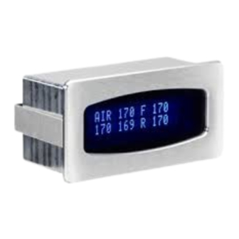
DUAL, TRIPLE, or QUAD AIR PRESSURE GAUGE
Features:
•
All pressure readings displayed at once on a 2-line display.
•
Optional storage tank pressure readout.
•
A warning feature that flashes the gauge readout when outside operating limits.
•
An output for an external warning light or buzzer.
•
User adjustable warning points.
•
Individual settings for front, rear, and tank warning points.
•
Microprocessor stabilized readings.
•
Quick-Start feature to provide accurate readings quickly after being powered up.
•
Automatic Night dimming.
•
High Visibility, full character VFD display.
•
Automatic display selection for two or four sender operation.
The air pressure gauge will read wet or dry air pressure. The sender used for this
gauge is an oil pressure sending unit, so it is compatible with air, water, oil, and fuel. The air
pressure gauge will operate and read correctly between the pressure range of 0 - 145 psi
using the SEN-03-1 senders and 0-400 psi using the SEN-03-5 senders. The gauge has a
user adjustable low and high warning level.
Operation:
The gauge needs only the PWR and GND terminals connected to light up. When the
DIM terminal has 12 volts, it will dim the display for night viewing. The R-R, L-R, R-F, L-F,
and TNK terminals are for the pressure senders. The senders must be Dakota Digital part
SEN-03-1 or SEN-03-5. Sending units from other manufacturers will cause incorrect
readings. SEN-03 has 1/8" NPT threads. If other thread sizes are needed, an adapter fitting
should be used to change the thread size. If a sender is giving an incorrect reading, the
display will show "EE". If the sender is shorted to ground, the display will show "--".
The display will flash and the warning output will be set whenever one of the displayed
pressures is out of the warning set limits.
Using external warning indicators:
The WRN terminal provides a ground trigger whenever any of the senders are outside
the set limits. Low current indicators (less than 1/4 A) can be activated directly by connecting
their power wire to 12 volts and connecting their ground wire to the WRN terminal.
For higher current buzzers or lights, a relay will need to be used to switch the indicator
on. Dakota Digital's RLY-1 30A relay may be used for this. One of the coil wires should be
connected to 12 volts and the other coil wire connected to the WRN terminal. When the
gauge is outside its limits, the relay will turn on. The relay contact wires can be used to
switch the higher current.
ODY-19-4 rev. D
1
MAN#650044
Advertisement
Table of Contents

Related Manuals for Dakota Digital Odyssey ODY-19-4


Summary of Contents for Dakota Digital Odyssey ODY-19-4
- Page 1 For higher current buzzers or lights, a relay will need to be used to switch the indicator on. Dakota Digital’s RLY-1 30A relay may be used for this. One of the coil wires should be connected to 12 volts and the other coil wire connected to the WRN terminal. When the gauge is outside its limits, the relay will turn on.
- Page 2 WARNING! CONNECTING A HIGH CURRENT INDICATOR DIRECTLY TO THE WARNING OUTPUT WILL DAMAGE THE UNIT. Setting the warning limit and sender type: The low and high warning limits can be set to different values, also the front bag, rear bag, and tank warnings can each be set differently. The TNK terminal is used for setting the warning limit.
- Page 3 Wiring: PWR - connect to 12 volt accessory power. GND - connect to a good ground point in the vehicle. TNK - connect to tank pressure sender (optional). connect to the tail light circuit. WRN - can connect to the negative side of a relay, light, or buzzer. The TNK terminal should be left open if the tank pressure is not being monitored.
- Page 4 Mounting: The gauge requires a rectangular cut out that is about 2 7/8“ x 1 11/16“. It should be inserted into the opening from the front and the U-clamp will be installed from the back. Tighten the two nuts on the U-clamp so that the gauge is secure. Figure 2 shows the required cut out for the gauge.
- Page 5 Troubleshooting guide. Problem Possible cause Solution Gauge will not light up PWR terminal does not have Connect to a location that has power. power. GND terminal is not getting Connect ground to a different location. a good ground. Case-to-display ground Connect a ground wire to the display case.
- Page 6 Any action for breach of any warranty hereunder, including any implied warranty of merchantability, must be brought within a period of 24 months from date of original purchase. No person or representative is authorized to assume, for Dakota Digital, any liability other than expressed herein in connection with the sale of this product.
Need help?
Do you have a question about the Odyssey ODY-19-4 and is the answer not in the manual?
Questions and answers