Table of Contents
Advertisement
Quick Links
Operating Instructions
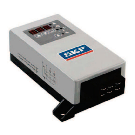
IG502-2-E - Universal control unit
(for commercial vehicles) for NLGI
Also as a replacement for the following predecessor models: IG471-21, IG472-11, IG434-1, IG472-22, IG433-5-51, ...
Created on:
19.01.2023
Document no.:
951-180-193-EN
Version:
01
Read these instructions before
installation or start-up of the
product and keep them readily
available for later consultation!
Advertisement
Table of Contents

Related Manuals for Lincoln SKF IG502-2-E


Summary of Contents for Lincoln SKF IG502-2-E
- Page 1 Operating Instructions IG502-2-E - Universal control unit (for commercial vehicles) for NLGI Also as a replacement for the following predecessor models: IG471-21, IG472-11, IG434-1, IG472-22, IG433-5-51, ... Created on: 19.01.2023 Document no.: 951-180-193-EN Version: Read these instructions before installation or start-up of the product and keep them readily available for later consultation!
- Page 2 EU Declaration of Conformity in accordance with Directive 2014/30/EU, Annex IV The manufacturer hereby declares under its sole responsibility conformity of the product described below with all relevant harmonization legislation of the European Union at the time of placing on the market. Designation: Universal control unit for use in centralized lubrication systems for commercial vehicles Type / item number:...
-
Page 3: Masthead
SKF (U.K.) Limited, 2 Canada Close, Banbury, Oxfordshire, OX16 2RT, GBR. - North America - SKF Lubrication Business Unit Lincoln Industrial 5148 North Hanley Road, St. Louis, MO. 63134 USA - South America - SKF Argentina Pte. Roca 4145, CP 2001 Rosario, Santa Fe... -
Page 4: Table Of Contents
6.7.6 Programming ranges ..........22 Table of contents 6.7.7 Display ranges ............. 23 6.8 Operating modes..............23 Masthead ....................3 6.8.1 Timer operation (pause and pump operation are Table of contents ................. 4 time-dependent) ..............23 Safety alerts, visual presentation, and layout ........ 5 6.8.2 Counter operation (pause depends on the number of pulses) ................. -
Page 5: Safety Alerts, Visual Presentation, And Layout
1. Instruction steps: These indicate a chronological sequence Safety alerts, visual of instruction steps. The numbers of the steps are in bold and are followed by a period. If a new activity follows, the presentation, and layout numbering starts again at “1.” –... -
Page 6: Safety Instructions
1.3 General behaviour when handling the 1. Safety instructions product 1.1 General safety instructions • Familiarize yourself with the functions and operation of the product. The specified assembly and operating steps and their • Putting the products into operation or operating them without sequences must be observed. -
Page 7: Referenced Documents
1.6 Referenced documents 1.11 Notes on CE marking In addition to this manual, the following documents must be CE marking is effected following the requirements observed by the respective target group: of the applied directives requiring a CE marking: • Company instructions and approval rules If applicable: •... -
Page 8: First Start-Up, Daily Start-Up
Drill required holes only on non-critical, non-load-bearing parts of the operator's infrastructure. Use existing holes where possible. Avoid chafe points. Immobilize any moving or detached parts during the work. Adhere to the specified torques. If guards or safety devices need to be removed, they must be reinstalled immediately following conclusion of work and then checked for proper function. -
Page 9: Overview, Functional Description
Fig. 3 2. Overview, functional description 2.1 Functional description The IG502-2-E universal control unit is used to control and monitor centralized lubrication systems on commercial vehicles. The control unit's functions can be programmed. NOTE Replacement of previous SKF control units: see section 5.3 Predecessor model being replaced –... -
Page 10: Technical Data
3. Technical data Table 1 Technical data Designation Value <Co ntent> Nominal voltage UN DC: 12 V or 24 V Enclosure rating IP 20, DIN 40050 / plug IP 00 Max. load, output M 5 A at 24 V, 5 A at 12 V SL output Data retention Unlimited... -
Page 11: Delivery, Returns, Storage
4.5 Declaration of decontamination 4. Delivery, returns, storage If the product came in contact with harmful substances, make 4.1 Delivery sure to thoroughly clean the product before returning it to us. Due to statutory provisions and for the safety of our employees After receipt of the shipment, it must be inspected for any and operation facilities we further need a fully completed and shipping damage and for completeness according to the... -
Page 12: Assembly
5.1 Overview of the electrical connections 5. Assembly Fig. 7 The unit must be installed inside a closed area in the vehicle, where it is protected from environmental influences Fig. 5 Electrical connection assignment diagram Fig. 8 Mounting lugs The unit is mounted using lugs (Fig. 5). The IG502-2-E is contained in a housing that meets protection class IP 20. -
Page 13: Replacing Other Control Units
1. Read the item number (IG..) printed on the old unit that you 5.2.2 Replacing other control units are replacing, in order to determine the operating mode that you need to program on the new IG502-2-E unit. Section 5.3 Predecessor model being replaced – programming 2. -
Page 14: Activation Of A Pneumatic Pump
5.4 Activation of a pneumatic pump 5.4.1 Operation without electronic system monitoring NOTE Only on centralized lubrication systems for NLGI Grade 00 NOTE and 000 greases! System malfunctions are not automatically detected or displayed. Monitoring is switched off. COP = OFF (see section 6.7 Programming- "Changing the The pneumatic pump is activated by a 3/2 directional control system monitoring") valve. -
Page 15: Operation
6. Operation 6.1 Display and operating unit The layout of the screen has changed since 2007. For clarification, Table 3 presents the symbols on the new screen next to the labeling on the old front panel. Fig. 10 Display and operating unit Table 3 Display and control elements of control screen Image... - Page 16 Table 4 Three-digit LED display Display Meaning Statement Control function t = TIMER The control unit is functioning as Part of the lubrication cycle PA = PAUSE a timer and is currently in PAUSE Input value and display value in mode hours c = COUNTER...
-
Page 17: Function Indication By Leds
6.3 Function indication by LEDs Table 5 Function indication by LEDs LED lights up = display mode LED flashes = programming mode Operating voltage is present on pump unit and control unit, system is Value for PAUSE can be changed currently in operating status PAUSE Operating voltage is present on pump unit and control unit, system is Value for CONTACT can be changed... -
Page 18: Display Mode
6.6 Display mode Display mode can be identified by the lit-up LED displays. The display does not flash. It is used to query the current settings and operating parameters. Always start the display mode by briefly pressing either of the two keys Table 7 Display mode Step... -
Page 19: Programming
Table 7 Display mode Step Button Display 10/11 Example: 1st part of total value 2nd part of total value Total value: 533.8 h Write down. Maximum value: 99999.9 h Display fault hours 13/14 Example: 1st part of total value 2nd part of total value Total value: 33.8 h Write down. -
Page 20: Changing The Pause Time Or Pump Run Time
6.7.2 Changing the pause time or pump run time Table 9 Changing the pause time or pump run time Step Button Display Display flashes (code 000 = factory setting) Press longer than 2 s Pause in timer operation "Pause" LED flashes Press briefly (confirm the code) Pause time 9 h... -
Page 21: Change Operating Modes
Table 10 Changing the system monitoring Step Button Display Monitoring via pressure switch (factory setting) Press briefly Press either until Monitoring via cycle switch System monitoring switched off "CS" LED flashes Confirm new setting Press briefly New settings are written to memory Display clears Press longer than 2 s 6.7.4 Change operating modes... -
Page 22: Change Code
6.7.5 Change code NOTE The factory-set code is now deleted and the new code is valid. Write down the new code and store it in a safe place. Without the code, the parameters cannot be programmed. The control unit would then have to be sent to the factory for rework. Table 12 Change code Step Button... -
Page 23: Display Ranges
6.7.7 Display ranges Table 14 Display ranges Function Display range Pause time 0.1 h to 99.9 h Pump cycle time 0.1 min to 99.9 min Pulses 1 to 999 Fault hours 0.1 h to 99999.9 h Operating hours 0.1 h to 99999.9 h 6.8 Operating modes CONTACT: Display values and programming values in... -
Page 24: Monitoring Via Pressure Switch
NOTE Operational malfunctions are automatically detected and displayed. Monitoring is switched on. COP = CS or PS(see section 6.7 Programming– "Changing the system monitoring"). If fill level monitoring is installed, W1 is always active. 6.8.6 Monitoring via pressure switch NOTE Only on centralized lubrication systems for NLGI Grade 00 and 000 greases! Fig. -
Page 25: Monitoring Via Cycle Switch
If the monitoring is switched off: see section 6.7 Programming"Changing the system monitoring". If possible, the pressure switch should be installed after the last metering device in the main line. It monitors the pressure build-up In the system during the CONTACT time. 6.8.7 Monitoring via cycle switch NOTE Only possible for centralized lubrication systems with progressive metering devices. -
Page 26: Replacement Unit
6.9 Replacement unit 6.9.1 Replacement of IG471-21 6.9.1.1 Quick reference guide for programming • To reprogram the IG502-2-E to the operating mode of the IG471-21, the factory settings must be changed as follows: Table 15 Replacement of IG471-21 Step Button Action Display Press longer than 2 s... -
Page 27: Replacement Of Ig472-11
6.9.2 Replacement of IG472-11 6.9.2.1 Quick reference guide for programming • Connection 30 is not used and must be removed from the connector plug • The minus input of the cycle switch must be moved to plus • To reprogram the IG502-2-E to the operating mode of the IG472-11, the factory settings must be changed as follows: Table 16 Replacement of IG472-11 Step Button... -
Page 28: Replacement Of Ig434-1
6.9.3 Replacement of IG434-1 6.9.3.1 Quick reference guide for programming • To reprogram the IG502-2-E to the operating mode of the IG434-1, the factory settings must be changed as follows: Table 17 Replacement of IG434-1 Step Button Action Display Press longer than 2 s Display flashes (code 000 = factory setting) Press briefly... -
Page 29: Replacement Of Ig472-22
6.9.4 Replacement of IG472-22 6.9.4.1 Quick reference guide for programming • To reprogram the IG502-2-E to the operating mode of the IG472-22, the factory settings must be changed as follows: Table 18 Replacement of IG472-22 Step Button Action Display Press longer than 2 s Display flashes (code 000 = factory setting) Press briefly... -
Page 30: Replacement Of Ig433-5-51
6.9.5 Replacement of IG433-5-51 6.9.5.1 Quick reference guide for programming • To reprogram the IG502-2-E to the operating mode of the IG433-5-51, the factory settings must be changed as follows: • The pump run time (tCO) and the system monitoring via pressure switch are not changed •... -
Page 31: Maintenance And Repair
7. Maintenance and repair The following maintenance and repair work must be performed on a regular basis: • Inspect the fill level in the lubricant reservoir • Regularly inspect the system components for leaks • Visually inspect the lubrication of the bearings •... -
Page 32: Cleaning
8. Cleaning 8.1 Basics Cleaning should be carried out in accordance with the operator's own company rules, and cleaning agents and devices and the personal protective equipment to be used should likewise be selected in accordance with those rules. Only cleaning agents compatible with the materials may be used for cleaning. -
Page 33: Faults, Causes, And Remedies
1. Start the display mode with either of the two keys . The 9. Faults, causes, and fault is displayed. remedies 9.2 Delete fault notification All fault notifications are displayed by the LED as a All fault notifications can be acknowledged and deleted using centralized fault notification. -
Page 34: No Signal From Cycle Switch
Table 21 Delayed signal from cycle switch Event Device Display on the control unit Signal from the cycle switch during the second pump run time Block operation is interrupted Start of the regular preset pause time Signal from the cycle switch during the second block pause Block operation is interrupted Pause is resumed until the end of the regular preset pause time... -
Page 35: Fault-Hours Counter
9.7.2 Fault-hours counter The fault-hours counter adds up all fault-state times occurring during operation. The current counter reading can be read in display mode in two blocks of three digits each by calling up the parameter Fh. See section 6.6 Display modesteps 12–14. The maximum reading that can be displayed is 99999.9 hours. -
Page 36: Repairs
10. Repairs < WARNING Risk of injury At a minimum, the following safety measures must be taken before any repairs: • Unauthorized persons must be kept away • Mark and secure the work area • Depressurize the product • Isolate the product, and lock and tag it out •... -
Page 37: Appendix
13. Appendix 13.1 China RoHS Table Table 23... - Page 38 ® SKF and Lincoln are registered trademarks of the SKF Group. ™ eLube is a trademark of the SKF Group. © SKF Group 2023 Reprint or reproduction of the contents of this information - even in part - is permitted only with SKF's prior written consent.
Need help?
Do you have a question about the SKF IG502-2-E and is the answer not in the manual?
Questions and answers