Advertisement
Available languages
Available languages
Quick Links
Advertisement

Subscribe to Our Youtube Channel
Related Manuals for SystemAir FHW12


Summary of Contents for SystemAir FHW12
- Page 1 FHW12, FHW22, FHW32, FHW33 ... 19 ... 33 ... 37 ... 24 ... 28...
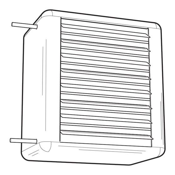
- Page 2 FHW12, FHW22, FHW32, FHW33 Measures 1 Fan heater 2 Mounting fi xtures 3 Filter net 4 Filter section, deep-pleated bagfi lter EU3 5 Return air intake 6 Mixing cabinet with damper 7 Outer wall grill 8 Extra air director, adjustable louvres...
- Page 3 FHW12, FHW22, FHW32, FHW33 FHWC FHWWG Outer wall grill Consolles FHW12 FHW22 FHW32/33 FHW12 FHW22 FHW32/33 D Ø FHWF Filter section Ø 10 FHW12 FHW22 FHW32/33...
- Page 4 FHW12, FHW22, FHW32, FHW33 FHWD Ø10 Return air intake FHW12 FHW22 FHW32/33 FHWMC Mixing cabinet with damper Ø 10 Ø 10 FHW12 FHW22 FHW32/33 G Ø...
- Page 5 FHW12, FHW22, FHW32, FHW33 FHWACT FHWR3 REX2000 3-stage Switch FHW2RV20/25 RE3 - 7 (transformer) 5-stage Switch SR 122 2 stage thermostat Type Current [A] Fuse [A] Ensclosure A [mm] B [mm] C [mm] Weight [kg] IP 54 IP 54...
- Page 6 FHW12, FHW22, FHW32, FHW33 Wiring diagrams FHW12 and FHW22 Preset fan speed, no regulation No bridges for fan speed 1 Bridge 1-2 for fan speed 2 1 2 3 4 5 6 7 8 ˚ 230 V~ Bridge 1-2-3 for fan speed 3...
- Page 7 FHW12, FHW22, FHW32, FHW33 Wiring diagrams FHW32 and FHW33 Preset fan speed, no regulation max speed Thermostat SR121 (IP54) and 5-stage regulation RE3 or RE7 Z2 Z1 U2 U1 TK TK FHW32/33 FHWACT Z2 Z1 U2 U1 TK TK FHW32/33 FHW2RV20/25 L 1...
- Page 8 FHW12, FHW22, FHW32, FHW33 Motordata Current [A] Motor input [kW] Voltage [V] Thermocontact Protection class FHW12 0,20 ja / yes* IP 44 FHW22 0,25 ja / yes* IP 44 FHW32 0,45 ja/ yes* IP 44 FHW33 0,45 ja / yes*...
- Page 9 FHW12, FHW22, FHW32, FHW33 Pressure drop over FHW water coils m /h Pressure drop over regulations and valves (water) Q [m3/h] 0.01 0.01 Q [l/s] The pressure drop is calculated for an average temperature of 70°C (PVV 80/60). For other temperatures, the pressure drop is multiplied with the factor K.
- Page 10 FHW12, FHW22, FHW32, FHW33 General recommendations FHW without accessories Carefully read this instruction manual before Measure and mark the drilling holes on the wall or installation and use of the FHW unit. Keep these on the celing. Use a suitable screwing device to fi t instructions in a safe place for future reference.
- Page 11 (with no other accesories on gap. the inlet side), the mixing box must be dismantled. The following applies to FHW12 och FHW22 only: The fan motor is connected via a cable gland in the casing, to a terminal box inside the unit. Bottom...
- Page 12 Replacement fi lter of 20 mm frame width: Fan speed and heating regulation WxH [mm] Number of bags The fan motors for FHW12 and FHW22, are in FHWEF1 415x390x350 standard designs prepared for multiple fan speed, FHWEF2 525x470x400 see wiring diagram on page 6.
- Page 13 FHWAV20 FHWAV25 FHWF3 Filter section FHW32 och FHW33 2-way regulation valve FHW2RV20FHW2RV25 FHWD1 Air intake for fi lter section FHW12 Valve motor FHWACT FHWD2 Air intake for fi lter section FHW22FHWD3 Air intake for fi lter section FHW32/ FHW33 • FHWSV20/25, stop valve FHWEF1 Extra fi...
- Page 14 FHW12, FHW22, FHW32, FHW33 Recommandations générales Le raccordement en eau peut se faire aussi bien à Lire attentivement ce manuel avant l´installation e droite qu`à gauche. Il ne faut jamais les raccorder la mise en route de l´appareil. Garder la notice à...
- Page 15 fi ltre, l´inspection peut se faire par la trappe de visite de la boite à fi ltre. Pour les modèles FHW12 et FHW22. Quand l´aérotherme est utilisé avec une boite de L´alimentation électrique se fait sur le bornier interne mélange, celle ci doit être démontée pour procéder...
- Page 16 2000kPa (20 bars). Perte de charge maximum: Variation de débit et de puissance chauffage. 100kPa (0,1 bar) pour FHW2RV20, 62kPa (0,062 Les moteurs équipant les modèles FHW12 et bar) pour FHW2RV25.Le Kv est ajustable, 3 FHW22 sont à plusieurs vitesses. Voir diagramme positions.
- Page 17 Boite à fi ltre FHW22 FHWF3 Boite à fi ltre FHW32 och FHW33 FHWD1 Prise d`air pour boite à fi ltre FHW12 FHWD2 Prise d`air pour boite à fi ltre FHW22 FHWD3 Prise d`air pour boite à fi ltre FHW32/ FHW33...
- Page 18 FHW12, FHW22, FHW32, FHW33 Allgemeine Empfehlungen müssen separat bestellt werden. Bitte lesen Sie vor der Installation und FHW kann für horizontalen Ausblas an der Wand Inbetriebnahme des FHW-Gerätes diese oder für vertikalen Ausblas an der Decke montiert Bedienungsanleitung gründlich durch. Verwahren werden.
- Page 19 Ausrichtung des Luftstromes seitwärts: Werkseits 3mm Weg geschützt werden. ist FHW mit einem Strömungsgitter zur vertikalen Folgende Hinweise gelten nur für die Typen FHW12 Ausrichtung des Luftstromes ausgestattet. Das oder FHW22: Der Ventilatormotor wird durch zusätzliche Strömungsgitter wird durch Einhängen eine im Gehause eingebaute PG-Verschraubung in das bereits vorhandene Gitter montiert.
- Page 20 Luftstrom durch das Gerät behindern könnte! - Die Geräteoberfl ächen können während des Betriebes heiß werden! Ventilatordrehzahl- und Heizungsregelung Die Ventilatormotoren in den Ausführungen für FHW12 und FHW22 sind standardmäßig für den Betrieb mit verschiedenen Drehzahlen vorgesehen...
- Page 21 FHWAV20/25, Einstellventil FHWR2 3-Stufenschalter für den Luftstrom Stellt die Wassermenge auf die gewünschte Menge Gütlig nur für FHW12 und FHW22. Steuerung des Luftstromes in drei Stufen (0-1-2-3). ein (kv-Wert für FHWAV20: 0,13 - 5,9. Kv Wert für Es können bis zu 6 FHW-Geräte angesteuert erforderlich FHWAV25: 0,17 - 8,52.) Falls Wartung...
- Page 22 FHW12, FHW22, FHW32, FHW33 Zubehör FHWK1 Montagewinkel FHW12 FHWK2 Montagewinkel FHW22 FHWK3 Montagewinkel FHW32/ FHW33 FHWAD1 Separates Strömungsgitter FHW12 FHWAD2 Separates Strömungsgitter FHW22 FHWAD3 Separates Strömungsgitter FHW32/FHW33 FHWF1 Filterteil FHW12 FHWF2 Filterteil FHW22 FHWF3 Filterteil FHW32 oder FHW33 FHWD1 Einströmdüse für Filterteil FHW12 FHWD2 Einströmdüse für Filterteil FHW22...
- Page 23 FHW12, FHW22, FHW32, FHW33 Raccomandazioni generali FHW senza accessori Leggete attentamente queste istruzioni prima Misurare e segnare i fori sul muro o sul soffi tto. Usare dell’installazione e dell’uso dell’unità FHW. Mettetele delle viti adatte per fi ssare le mensole. Usare il set di poi in un luogo sicuro se dovessero servire in futuro.
- Page 24 fi ltro stessa. Per ispezionare il ventilatore Quanto di seguito esposto si applica solo alle unità quando viene utilizzato la camera di miscelazione FHW12 o FHW22: il motore del ventilatore è collegato, (senza altri accessori nel lato entrata), la camera stessa deve essere smontata.
- Page 25 FHW2RV20/25, valvola regolazione a 2-vie riscaldamento Classe pressione PN16, Pressione massima 2000kPa Il motori del ventilatore per FHW12 e FHW22, sono (20 Bar). Pressione massima discesa FHW2RV20, progettati in maniera standard per una velocità 100kPa (0,1 Bar). Pressione massima discesa del ventilatore multipla;...
- Page 26 FHW12, FHW22, FHW32, FHW33 Accessori FHWD1 Immissione aria per sezione fi ltro FHW12 FHWD2 Immissione aria per sezione fi ltro FHW22 FHWD3 Immissione aria per sezione fi ltro FHW32/FHW33 FHWEF1 Extra fi ltercassette EU3 FHW12 FHWEF2 Extra fi ltercassette EU3 FHW22 FHWEF3 Extra fi...
- Page 27 FHW12, FHW22, FHW32, FHW33 Èíñòðóêöèÿ ïî óñòàíîâêå è ïðèìåíåíèþ òåïëîâåíòèëÿòîðîâ ñ ïîäâîäîì ãîðÿ÷åé âîäû Âñå ìîäåëè òåïëîâåíòèëÿòîðîâ ïîñòàâëÿþòñÿ Îáùèå ïîëîæåíèÿ ñ ôðîíòàëüíîé ðåøåòêîé è ëîïàñòÿìè æàëþçè Âíèìàòåëüíî ïðî÷èòàéòå íàñòîÿùóþ èç àíîäèðîâàííîãî àëþìèíèÿ ñ âîçìîæíîñòüþ Èíñòðóêöèþ ïåðåä óñòàíîâêîé è èõ íåçàâèñèìîãî ïîâîðîòà äëÿ èçìåíåíèÿ...
- Page 28 òðåõïîëþñíûîãî ïåðåêëþ÷àòåëÿ ñ âîçäóøíûì ñíèìàåòñÿ è ôèëüòð óñòàíàâëèâàåòñÿ ïåðåä çàçîðîì íå ìåíåå 3ìì. òåïëîîáìåííèêîì íà ñïåöèàëüíûå íàïðàâëÿþùèå. Äëÿ ìîäåëåé FHW12 è FHW22 ìîòîð Èçâëå÷ü åãî äëÿ î÷èñòêè èëè îñìîòðà ìîæíî âåíòèëÿòîðà ñîåäèíÿåòñÿ êàáåëåì ñ êëåììíîé àíàëîãè÷íî, ñíÿâ îäíó èç êðûøåê.
- Page 29 ìîæíî ÷èñòèòü ñ ïîìîùüþ ïûëåñîñà. Êîãäà ïðèáîð èñïîëüçóåòñÿ áåç àêñåññóàðîâ, Óïðàâëåíèå ìîùíîñòüþ è âîçäóøíûì ïîòîêîì îöåíèòü ñîñòîÿíèå ïîâåðõíîñòåé ìîæíî âíåøíèì Ìîäåëè FHW12 è FHW22 â ñòàíäàðòíîì îñìîòðîì. Ñåêöèÿ ôèëüòðà îñìàòðèâàåòñÿ èñïîëíåíèè ïîçâîëÿþò îñóùåñòâèòü âûáîð ÷åðåç îòêðûâàþùóþñÿ êðûøêó â áîêîâîé ÷àñòè.
- Page 30 FHW12, FHW22, FHW32, FHW33 Ðåãóëèðîâêà òåìïåðàòóðû FHW2RV20/25 + ýëåêòðîïðèâîä FHWACT Ýòà êîìáèíàöèÿ ñîâìåñòíî ñ òåðìîñòàòîì ïîçâîëèò FHWR20/25, Êîìïëåêò âåíòèëåé àâòîìàòè÷åñêè ðåãóëèðîâàòü ïîäà÷ó âîäû íà Êîìïëåêò âåíòèëåé ïðåäíàçíà÷åí äëÿ âîäÿíóþ ñåêöèþ â çàâèñèìîñòè îò òåìïåðàòóðû, ðåãóëèðîâêè, îòêëþ÷åíèÿ/âêëþ÷åíèÿ ïîäà÷è çàäàííîé íà òåðìîñòàòå, íî áåç ðåãóëèðîâêè...
- Page 31 FHW12, FHW22, FHW32, FHW33 Ïðèíàäëåæíîñòè FHW2RV20 Äâóõõîäîâîé âåíòèëü DN20 (3/4”) FHWK1 Ìîíòàæíûå ñêîáû äëÿ FHW12 FHW2RV25 Äâóõõîäîâîé âåíòèëü DN25 (1”) FHWK2 Ìîíòàæíûå ñêîáû äëÿ FHW22 FHWK3 Ìîíòàæíûå ñêîáû äëÿ FHWACT Ýëåêòðîïðèâîä 2õ õîäîâîãî âåíòèëÿ FHW32/FHW33 (230Â, IP40) FHWAD1 Äîïîëíèòåëüíûå æàëþçè äëÿ FHW12 SR 121 Êîìíàòíûé...
- Page 32 Sweden SS-EN 60 555-2: 1987 SS-EN 60 555-3: 1987 The manufacturer hereby confi rms that the following products: Fan heaters FHW12, FHW22, FHW32 and FHW33 comply with the 60 335-2-30: 1992, A51, A52 following EC-directives: The complete technical documentation is Declaration of Incorporation available.
- Page 33 Systemair AB Systemair GmbH Industrivägen 3 Seehöfer Str. 45 739 30 Skinnskatteberg 97944 Windischbuch Sweden Germany Tel: +46 222 440 00 Tel: +49 7930 9272 0 Fax: +46 222 440 99 Fax: +49 7930 9272 92 mailbox@systemair.se info@systemair.de...
Need help?
Do you have a question about the FHW12 and is the answer not in the manual?
Questions and answers