Subscribe to Our Youtube Channel
Summary of Contents for SystemAir PTC - DN125
- Page 1 PTC – DN125 Installation and Operating Instructions Document in original language | 398046 · v1.1...
- Page 2 This also applies to products already ordered, as long as it does not affect the previously agreed specifications. Systemair is not liable or bound by the warranty if these instructions are not adhered to during installation or service. 398046 | v1.1...
-
Page 3: Table Of Contents
Contents Introduction ...........1 Product description.........1 Intended Use.........1 Document description ......1 Product overview ........1 Product liability ........2 Safety............2 Safety definitions ........2 Safety instructions........2 Personal protective equipment....3 Transportation and storage........3 Installation.............3 To do before the installation of the product ..........3 To install the product.......4 Electrical connection ........4 To do before the electrical connection..........4... -
Page 5: Introduction
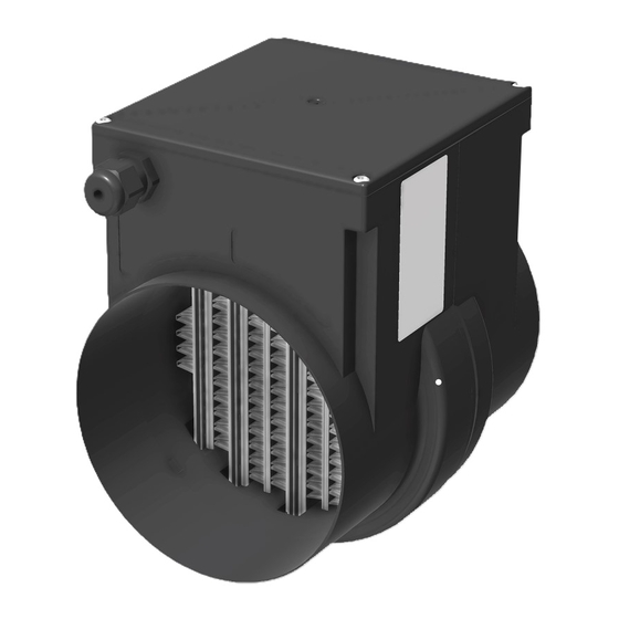
This document contains instructions for installation, operation and maintenance of the product. The procedures must be done by approved personnel only. Speak to Systemair for more information on how to install the product in different installation locations. Product overview The product can be controlled either by an analogue voltage signal or a PWM signal. -
Page 6: Product Liability
Systemair is not liable for damages that the product causes in these conditions: • The product is incorrectly installed, operated or maintained. • The product is repaired with parts that are not original spare parts from Systemair. • The product is used together with accessories that are not original accessories from Systemair. -
Page 7: Personal Protective Equipment
• If the maintenance is not correctly and regularly done, there is risk of injury and damage to the product. • Only do the maintenance as given in this manual. Speak to Systemair technical support if other servicing is necessary. -
Page 8: To Install The Product
| Electrical connection • Make sure that all cable glands are tight against the cables to prevent leaks. To install the product • The product can be installed horizontally or vertically in the air duct. Warning The product installation with electronic housing pointing downwards is not allowed. Possible condensate in the ventilation system can otherwise penetrate the housing and cause damage to the electronics. -
Page 9: To Connect The Product To The Power Supply
Electrical connection | Line Requirement Cross-section area: 3 x 1,5 mm Power supply 230 VAC Line layout: single-wire or multi-wire Maximum cable diameter: 8 mm Recommended length for individual wires (L, N, PE): 80 Combined line for control signal (10 VDC) and error signal Rated voltage for the line allowed up to 230 VAC Cross-section area: 4 x 0,5 mm relay (230 VAC) -
Page 10: Commissioning
| Commissioning Fig. 3 Wiring Description Terminal Name Connection Error signal relay (normally- Error signal Max. 230 VAC open contact) analogue control signal 0 – 10 VDC 0 V control signal (GND) Combined reference PWM control signal 10 VDC Supply voltage L 230 VAC Supply voltage N Functional ground... -
Page 11: Maintenance
Caution • Repairs are not permitted. Troubleshooting Note: If you cannot find a solution to your problem in this section, speak to Systemair technical support. Problem Possible causes Solutions No heating power. • Supply voltage cable not •... -
Page 12: Disposal
| Disposal Problem Possible causes Solutions Increased heating power. • Voltage of the control signal is too • Check external controller settings. high. • Check the minimum air flow. • External controller is not working • Check position and function of external correctly. -
Page 13: Technical Data
Technical data | Technical data Type PTC – DN125 – 0.8 kW PTC – DN125 – 1.2 kW 850 W (+5/-10%) 1200 W (+5/-10%) Maximum power * Differential pressure ** 25 Pa 36 Pa Maximum inrush current Nominal voltage 230 VAC Standby power 0,5 W Analogue control voltage... -
Page 14: Eu Declaration Of Conformity
| EU Declaration of Conformity EU Declaration of Conformity Manufacturer Systemair UAB Linų st. 101 LT–20174 Ukmergė, LITHUANIA Office: +370 340 60165 Fax: +370 340 60166 www.systemair.com hereby confirms that the following products: PTC – DN125 – 0.8 kW, PTC – DN125 – 1.2 kW (The declaration applies only to product in the condition it was delivered in and installed in the facility in accordance with the included installation instructions. - Page 15 398046 | v1.1...
- Page 16 Systemair UAB Linų st. 101 LT–20174 Ukmergė, LITHUANIA Phone +370 340 60165 Fax +370 340 60166 www.systemair.com...


Need help?
Do you have a question about the PTC - DN125 and is the answer not in the manual?
Questions and answers