Advertisement
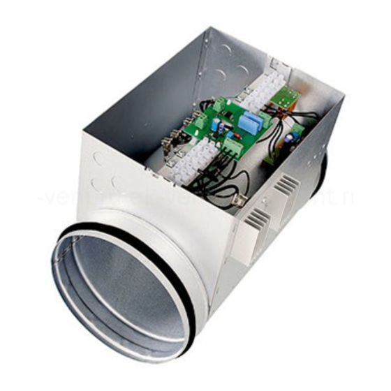
CBMB
MONTERINGSANVISNING
SE
för kanalvärmare med inbyggd temperaturregulator och elektronisk flödesvakt
avsedd att monteras i cirkulära ventilationskanaler.
!
VIKTIGT:
FITTING INSTRUCTION
GB
for duct heaters with buit-in temperature control and airflow monitor
designed for mounting in circular ventilation ducts.
!
IMPORTANT:
before installation and connection of the product.
Läs denna instruktion innan produkten monteras och ansluts.
Please read this instruction
-
...
...
Advertisement
Table of Contents

Subscribe to Our Youtube Channel
Related Manuals for SystemAir CBMB Series


Summary of Contents for SystemAir CBMB Series
- Page 1 CBMB MONTERINGSANVISNING för kanalvärmare med inbyggd temperaturregulator och elektronisk flödesvakt avsedd att monteras i cirkulära ventilationskanaler. VIKTIGT: Läs denna instruktion innan produkten monteras och ansluts. FITTING INSTRUCTION for duct heaters with buit-in temperature control and airflow monitor designed for mounting in circular ventilation ducts. IMPORTANT: Please read this instruction before installation and connection of the product.
- Page 2 Installation 1. Kanalvärmaren är tillverkad för 1-fas eller 3-fas växelström. Se elschema för aktuell värmare samt märkdata på typskylten som är placerad på värmarens lock. 2. Kanalvärmaren måste anslutas till nätet med fast förlagd rund kabel. Kabelgenomföringar skall väljas av sådan typ att värmarens kapslingsklass bibehålles.
- Page 3 Connection to mains 1. The duct heater is designed to operate on single phase or three phase alternating current. See further the wiring diagram for the particular heater and the electrical data on the rating plate, placed on the lid of the duct heater. 2.
- Page 4 Kopplingsschema / Wiring diagram 15 16 L1 L2 330? 330? CBMB-1 CBMB-3 (230V~) (400V 3~) A = Värmeelement / Heating elements B = Automatiskt återgående överhettningsskydd / Over heat protection with automatic reset C = Manuellt återställbart överhettningsskydd / Over heat protection with manual reset F = Allpolig brytare / All phase breaker H = Regulator typ Pulser eller TTC / Controller type Pulser or TTC J = Givare / Sensor -20...+10 C ( TG-K310 )
- Page 5 OBS ! Kretskortet är spänningsförande när värmarens matningsspänning är ansluten. A = Intern börvärdespotentiometer. Används inte i denna typ av värmare. B = Bygel (Int/Ext) skall vara SLUTEN. C = Trimpotentiometer justerad vid tillverkningen av regulatorn. Ändra INTE inställningen! D = Börvärdesinställning för MIN-begränsning. Används inte i denna typ av värmare. E = Börvärdesinställning för MAX-begränsning.
- Page 6 Felsökning ● Kontrollera att luftflödet är tillräckligt genom värmaren. Luftflödet är otillräckligt om den gula lysdioden på kretskortet är tänd, alternativt kan luftflödet vara tillräckligt men alltför turbulent för att elektroniken skall kunna mäta flödet som tillräckligt och då förblir den gula lysdioden tänd med utebliven värme. Dock behöver mätgivaren ett par minuters uppvärmningstid efter att värmarens matningsspänning har kopplats till.
- Page 7 Trouble-shooting ● Check that the airflow through the heater is sufficient. The airflow is insufficient if the yellow LED on the PCB is light up, or the airflow might be sufficient but too turbulent for the electronics to be measured as sufficient, then the yellow LED will sustain light up and there will be no heating.
- Page 8 SE-739 30 SKINNSKATTEBERG SWEDEN Telefax +46 (0)222-440 99 Phone +46 (0)222-440 00 www.systemair.com...
Need help?
Do you have a question about the CBMB Series and is the answer not in the manual?
Questions and answers