Table of Contents
Advertisement
Quick Links
Uf 841
(full pipe)
User manual
Bâtiment Texas – Éragny Parc
9, Allée Rosa Luxemburg
95610 ÉRAGNY SUR OISE, FRANCE
Tel.: 33 (0)1 30 27 27 30
Fax: 33 (0)1 30 39 84 34
2014 ULTRAFLUX S.A.
All rights reserved. No part of this document may be reproduced without prior written authorisation from
ULTRAFLUX S.A. ULTRAFLUX, Uf 841 are registered trademarks of ULTRAFLUX S.A.
NT UF 841 CP GB (d) / June 2015
Advertisement
Table of Contents

Related Manuals for Ultraflux Uf 841


Summary of Contents for Ultraflux Uf 841
- Page 1 Fax: 33 (0)1 30 39 84 34 2014 ULTRAFLUX S.A. All rights reserved. No part of this document may be reproduced without prior written authorisation from ULTRAFLUX S.A. ULTRAFLUX, Uf 841 are registered trademarks of ULTRAFLUX S.A. NT UF 841 CP GB (d) / June 2015...
-
Page 2: Table Of Contents
3.2 Attachment ___________________________________________________________________ 18 3.3 Opening the casing ____________________________________________________________ 20 3.4 Wiring instructions _____________________________________________________________ 20 3.5 Connection to the protective ground (to be carried out first) ____________________________ 21 3.6 Wiring the Terminals ___________________________________________________________ 21 NT UF 841 CP GB (d) / June 2015... - Page 3 4.2 Choosing the measurement location _______________________________________________ 26 4.3 Choosing the probe location _____________________________________________________ 30 4.4 Installing probes and connectors __________________________________________________ 32 CHAPTER 5: USING AND CONFIGURING THE Uf 841 ___________________ 5.1 Using the Uf 841 ______________________________________________________________ 36 5.2 Main configuration elements _____________________________________________________ 39 5.3 Configuring the Uf 841 _________________________________________________________ 39...
-
Page 4: Chapter 1: Overview
CHAPTER 1: OVERVIEW NT UF 841 CP GB (d) / June 2015... -
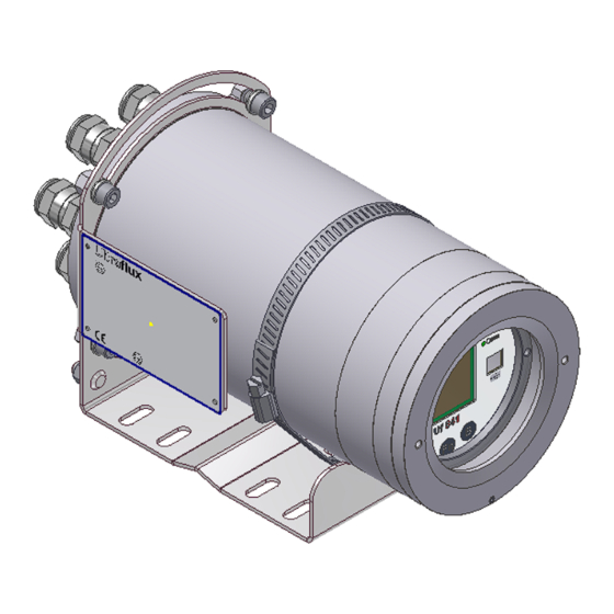
Page 5: Overall View Of The Converter
1.1 Overall view of the converter 1.1.1 Unit closed Cable glands Identification plate Screen Mounting General view Probe inputs Lights Keys Protective ground connection Front view without cover Rear view NT UF 841 CP GB (d) / June 2015... -
Page 6: Unit Open
1.1.2 Unit open Ultrasonic chord Input-output connections connections Jumpers for cable shield Serial link grounding connection Power supply connection Lower view Upper view connector Displayer view NT UF 841 CP GB (d) / June 2015... -
Page 7: Functions
1.2 Functions The UF 841 is an ultrasonic flow meter used to measure flows using the transit time difference method. The measurement can be taken using an installation with up to 4 ultrasonic measurement chords. (One chord designates the acoustic path between two probes, each alternating between emitting and receiving. -
Page 8: Power Supply
1.7 Communication The Uf 841 has a serial link which can be wired using RS232 or RS485 mode, as well as a USB port. For this communication interface, the standard protocol chosen is the Slave JBUS (MODBUS). This enables the unit to be connected to an instrumentation and control system or to a computer. -
Page 9: Inputs/Outputs
• 1.9 Ultrasound chords The Uf 841 enables the control of a maximum of 4 ultrasonic chords, or 8 probes. 8 cable glands are provided to pass the probe cables through. In principle, only ultrasonic probes supplied by Ultraflux may by used with the Uf 841. Ultraflux accepts no responsibility for damage or incidents which may occur following a failure to respect these instructions. -
Page 10: Operating Lights
To change a row, select it using p or q and change the value using t or u. • If no key is pressed for approximately one minute, the Uf 841 automatically returns to • "measurement" mode and to the display chosen as priority using "B". -
Page 11: Performance Of The Flow Meter
2009 relating to the collection, treatment and disposal of electrical and electronic equipment, batteries and accumulators in France, Ultraflux delegates the responsibility for financial and also logistical recovery to the user, who will manage their own waste. The separate collection and recycling of your waste at the time of its disposal will help to preserve natural resources and guarantee recycling that is least harmful to the environment and human health. -
Page 12: Chapter 2: Safety Instructions
CHAPTER 2: SAFETY INSTRUCTIONS NT UF 841 CP GB (d) / June 2015... -
Page 13: Using The Flow Meter
Should the temperature of the unit rise abnormally, it is recommended to power off the flow meter and call Ultraflux for expert advice. In the event of a fire inside the flow meter, power it off without opening or touching it, then call the competent services in order to secure the premises. -
Page 14: Symbols Used On The Flow Meter
Hazard risk; please refer to the precautions in these user instructions. The unit's protective ground must be connected. Do not throw in the bin. Follow the recycling procedure indicated in these instructions. NT UF 841 CP GB (d) / June 2015... -
Page 15: Maintenance Work On The Flow Meter
See paragraph 3.6 on wiring of the above terminal boards. 2.4 Maintenance work on the flow meter Work relating to maintenance on the flow meter must only be carried out by Ultraflux staff (SAV) and using only parts supplied by Ultraflux (*). -
Page 16: Contact Address
For any requests for information, please contact us at: ULTRAFLUX 9, Allée Rosa Luxemburg 95610 ERAGNY FRANCE http://www.ultraflux.net E-mail : ultraflux@ultraflux.fr Tel.: 33 (0)1 30 27 27 30 Fax: 33 (0)1 30 39 84 34 2014 ULTRAFLUX S.A. NT UF 841 CP GB (d) / June 2015... -
Page 17: Chapter 3: Installation And Wiring
CHAPTER 3: INSTALLATION AND WIRING NT UF 841 CP GB (d) / June 2015... -
Page 18: General
Before any operation on the unit, the user instructions NT300, supplied with the unit, must be read. The Uf 841 casing presents no particular danger to the user. Depending on the environment where the unit is installed, it is however recommended to wear personal protective equipment during assembly, including: gloves, safety boots, impact goggles. - Page 19 Pass the various cables through the cable glands, Connect the cables to the various terminals (see chapter 3.6), Tighten the cable glands (for the tightening torques, please refer to the cable gland user instructions). NT UF 841 CP GB (d) / June 2015...
-
Page 20: Opening The Casing
It is sometimes necessary to protect the inputs/outputs, the power supply and the ultrasonic chords. You are strongly recommended to contact Ultraflux to obtain a diagnosis on this point. Ultraflux accepts no responsibility in the event of the incorrect use of the flow meter, and in such cases, the Ultraflux guarantee would not be valid. -
Page 21: Connection To The Protective Ground (To Be Carried Out First)
For the ground connection, it is recommended to use a copper braid. When choosing the braid, it is important to adhere to the following rule: Length / Width < 3. At the end of the Uf 841 ground connection contact there should be an M6 stud bolt fitted with appropriate washers and nuts. In all cases, the section of the conductor used must be greater or equal to that of the device's power supply cable conductors (see §3.6.1). -
Page 22: Ultrasonic Chords
Connect the terminals to suitable positions, then place the shield connection jumper. Only tighten the knurled nuts at the end, ensuring the shield connection jumpers are correctly secured, avoiding pressure exertion on the contact plates placed below these jumpers. NT UF 841 CP GB (d) / June 2015... -
Page 23: Input/Output Terminals
4) Wiring of the relay modules Terminal pin configuration: Terminal pin configuration: Function Function Voltage A (+) relay A Voltage A (-) relay A Voltage B (+) relay B Voltage B (-) relay B NT UF 841 CP GB (d) / June 2015... -
Page 24: Wiring Of The Temperature Modules
To connect the shielding, it is recommended that the same precautions are followed as for the inputs/outputs and the ultrasonic chords (copper tape). Use shield connection jumpers designed for this purpose. NT UF 841 CP GB (d) / June 2015... -
Page 25: Chapter 4: Installing A Measuring Point
CHAPTER 4: INSTALLING A MEASURING POINT NT UF 841 CP GB (d) / June 2015... -
Page 26: Composition Of A Measuring Point
Apart from the electronic converter (the unit), a measuring point includes the following components: • 1 to 4 pairs of probes • 1 to 8 special cables for the probes (provided by Ultraflux) 4.2 Choosing the measurement location It is essential to follow the instructions given in our document “Ultrasonic ". - Page 27 NT UF 841 CP GB (d) / June 2015...
-
Page 28: Multichord Measurement
10 %. Recommended locations Vertical pipes with rising flow Low points of horizontal pipes Siphon mounting for pipes with a slight slope NT UF 841 CP GB (d) / June 2015... - Page 29 Locations not recommended Vertical pipe with downflow, particularly in the case of free flow. High points NT UF 841 CP GB (d) / June 2015...
-
Page 30: Choosing The Probe Location
For each chord, enter the length (in meters) between the faces of the two probes. To help you, read our document “Ultrasonic transit time flowmeter”. Also enter the projected length (Daxe) of this measurement relative to the axis of the pipe. NT UF 841 CP GB (d) / June 2015... - Page 31 On the other hand, the ultrasound echo will be weaker the longer the distance and therefore difficult to measure. A compromise must therefore be found between accuracy and ease of finding the ultrasounds. This compromise depends on the application (fluid, quality of the wall, diameter, etc.). NT UF 841 CP GB (d) / June 2015...
-
Page 32: Installing Probes And Connectors
- "traditional" gel for temporary measurements at ambient temperature and without too much humidity, - high temperature gel (<300°C), - grease in the case of high humidity (quality depending on temperature). NT UF 841 CP GB (d) / June 2015... -
Page 33: Installing The Probe
(the coupling medium film could be altered/broken). 4.4.3. Inserted probes Preliminary comment: before you do anything, you must check with Ultraflux whether your probes can be extracted under load or not. Whether an inserted probe may be extracted under load or not is determined by the probe used and the application conditions of your measuring point (pressure, fluid measured, etc.). -
Page 34: Screw Probes
2) Screw probes step: Check the position of the bosses relative to the drawing provided by Ultraflux step: Check the state of the seal face which must be free of irregularities and dirt. Seal faces which are rusted, battered or generally in a bad state of repair must not be used. -
Page 35: Chapter 5: Using And Configuring The Uf 841
CHAPTER 5: USING AND CONFIGURING THE Uf 841 NT UF 841 CP GB (d) / June 2015... -
Page 36: Using The Uf 841
Before using the unit, the user instructions NT300, supplied with the unit, must be consulted. The UF 841 has a screen and a keypad which can be used to configure and view the measurements as they are taken. LEDs indicate the status of the measurement and of the flow meter communication. -
Page 37: Keypad
If you are on the first page of a menu, pressing "A" causes selection of the last page of the menu. If you are on the last page of the menu, pressing "B" returns you to the first page. NT UF 841 CP GB (d) / June 2015... -
Page 38: Leds
• display is being used. "Measurement" Mode: After powering on the Uf 841, the machine moves into measurement mode after a few seconds and • displays the screen (or page) that was previously selected as priority. To choose this "default"... -
Page 39: Main Configuration Elements
Advanced: mode allowing the complete adjustment of the flow meter settings. This mode is • reserved for users with detailed knowledge of the transit time difference flow measuring technique and with some idea of hydraulic concepts. NT UF 841 CP GB (d) / June 2015... -
Page 40: Flow Meter Menu ("Settings" Mode)
ADVANCED CONFIGURATION: settings of the simulation mode, the special probes, the specific • codes for ultrasonic treatment, etc. ECHO DISPLAY: display of the echo signals of the ultrasonic probes. • FIRMWARE UPDATE: update of the firmware. • NT UF 841 CP GB (d) / June 2015... -
Page 41: Simple Configuration
This command reinitialises the flow meter (to factory configuration). 3) Confirmation (of reinitialisation) Reinitialisation of the flow meter requires the user to enter a field requiring confirmation (protection against handling errors). NT UF 841 CP GB (d) / June 2015... -
Page 42: Configuration
Each flow meter can be assigned a label with up to 8 characters (registration number). The position of the current character is chosen using the ▼ and ▲ keys. To scroll through the characters, use the < and > keys. NT UF 841 CP GB (d) / June 2015... -
Page 43: Back Light
3) Flow graph The flow graph is one of the Measurement screens. This shows the changes in a particular magnitude in the form of a curve (see the possible magnitudes below). NT UF 841 CP GB (d) / June 2015... -
Page 44: Chord Settings
5) Type of fluid In "simple" configuration mode, the fluid must be water at ambient temperature (cannot be modified). 6) Definition of the pipe The pipe diameter, thickness and material must be defined. NT UF 841 CP GB (d) / June 2015... -
Page 45: Totalizer Configuration" Menu (If Enabled)
Resetting totalizers is inhibited when the flow meter leaves the factory. On request and before shipping, it is possible to authorise the resetting of totalizers. On site, only an Ultraflux operative will be able to reset the totalizers. To reset a totalizer (if authorised): 1. -
Page 46: Inputs/Outputs" Menu (If Enabled)
Relay. The menu only appears if inputs or outputs are installed on the flow meter. To install additional inputs/outputs, please contact Ultraflux to find out the specifications of all available inputs/outputs. 1) Current input and voltage input module The possible options are: OFF: disabled, •... -
Page 47: Temperature Input Module
2) Temperature input module The possible options are: OFF: disabled, • PT100-PT1000 mode 2-, 3- or 4-wire (for further details, contact Ultraflux). • Define: the type of sensor, Pt 100 or Pt 1000, the type of assembly, 2-wire, 3-wire or 4-wire, the value of the filter and the memory, any offset. -
Page 48: Relay Output Module
Open: The relay remains constantly off. • Closed: The relay is on if the Uf 841 is powered on, and off if it is not powered on. This choice • therefore allows the relay to be used to detect the presence of the power supply (positive safety). - Page 49 Select the magnitude that you wish to associate with the output using the chapter headers (function) and the chapter items (value). the value relating to 0 hertz. the value relating to 1 Khertz. the value if a fault occurs. NT UF 841 CP GB (d) / June 2015...
-
Page 50: Logger Settings" Menu (If Enabled)
10 mins, 15 mins, 30 mins, 1 hr, 2 hrs, 6 hrs, 12 hrs and 24 hrs. 6) Logger autonomy This field, which cannot be changed, shows the remaining autonomy of the logger. NT UF 841 CP GB (d) / June 2015... -
Page 51: Logger Variables
Flow measurement Logger Time (s) The vertical lines (blue) show when logger recording is triggered. If the variation of the flow is greater than the configured threshold, the logger forces a recording. NT UF 841 CP GB (d) / June 2015... -
Page 52: Echo Display" Menu
The measurement is carried out on the first movement to 0 of the cycle which crosses this threshold. On the bottom left is shown the travel time difference of the ultrasounds (does not include ∆ T0). NT UF 841 CP GB (d) / June 2015... -
Page 53: Normal Configuration
Then the flow metering system faults itself if there are still no new valid flow rate measurements. Time Configured storage time NT UF 841 CP GB (d) / June 2015... -
Page 54: Filter
20 seconds, give the time constant a value of 40 or 60 s. However, you must ensure that the time constant is not too large, since this would risk masking significant events. NT UF 841 CP GB (d) / June 2015... -
Page 55: Delta T0 And Auto Zero
- change the Delta C to widen or shorten the search window. If the echo is on the right, the value of C must be lowered. Conversely, if the echo is on the left, the value of C must be increased. NT UF 841 CP GB (d) / June 2015... -
Page 56: Deletion Rate (Qeff)
6) Deletion rate (Qeff) The deletion rate is the flow rate below which the flow meter will display 0. This gives you a clear indication of a flow rate considered to be null. NT UF 841 CP GB (d) / June 2015... -
Page 57: Advanced Configuration
All type of material/layers can be used as long as they can transmit ultrasounds. If you cannot find your material in the predefined list, select OTHER and enter in addition of the thickness your material’s speed of sound. NT UF 841 CP GB (d) / June 2015... -
Page 58: Laminar/Turbulent Transition
Using the maximum gain setting, you can reject measurements if the gain exceeds the value entered in the flow meter. Important: You are strongly advised to contact Ultraflux before modifying these settings. NT UF 841 CP GB (d) / June 2015... -
Page 59: Weighting Coefficients Of The Chords
+ and – 0.8090 0.1382 Please feel free to contact Ultraflux to determine the value of the weighting coefficients. 5.6.2 "Linearisation settings" menu One last action possible on the flow is the linearisation of the result. Depending on the flow, the flow is corrected by X% based on a pre-defined table: The parameter Q ref defines the maximum flow used for the linearisation. -
Page 60: Advanced Settings" Menu
0 and 2 times the indicated value. 2) Special probes It may be necessary in certain cases to define a probe which is not referenced in the list of Ultraflux probes. Before using this option, you are strongly recommended to contact Ultraflux. -
Page 61: Measurement" Mode
(the higher the gain, the more difficult it is to • obtain a measurement), IQ quality index (100% indicates a very good measurement, 0% • indicates that the measurement is not possible). NT UF 841 CP GB (d) / June 2015... -
Page 62: Totalizers
This page shows the status of the logger and the last recording made. 7) Events These pages are used to find out whether there is a problem on the flow meter and to localize it in order to resolve it. NT UF 841 CP GB (d) / June 2015... -
Page 63: Distance Between Probes
The information from the various pages in the "measurement" mode allow you to check whether your measurements are consistent. The gain and IQ (Quality Index) values also provide you with information on the quality of your measurement. NT UF 841 CP GB (d) / June 2015... -
Page 64: Chapter 6: Function Engine
CHAPTER 6: FUNCTION ENGINE NT UF 841 CP GB (d) / June 2015... -
Page 65: Principle
6.1 Principle Each Uf 841 includes a miniature PLC. This PLC allows Ultraflux to easily install additional features for this flow meter. On request, Ultraflux can quickly integrate a new feature for your Uf 841. 6.2 Application examples: Calorimetry 6.2.1 Water temperature calculation The water temperature can be determined from its celerity (via a calculation). - Page 66 Caloric heat flow measurement on a heater 17:57:07 18:00:00 18:02:53 18:05:46 18:08:38 18:11:31 18:14:24 18:17:17 18:20:10 Time delta_T (°C) Power (kW) Energy (kW.h) NT UF 841 CP GB (d) / June 2015...
-
Page 67: Application Examples: Conversion Of Gas Flow Rate Into Standardised Flow Rate
This page gives the standard flow rate measured by the machine. Use the up and down navigation keys to display the standardised flow rate page. Standardised flow rate The standardised flow rate is given in Nm³/s or Nm³/h. NT UF 841 CP GB (d) / June 2015... -
Page 68: Chapter 7: Pc Software
CHAPTER 7: PC SOFTWARE NT UF 841 CP GB (d) / June 2015... -
Page 69: Introduction
The program is run by double-clicking the icon associated with the software and placed on the desktop, or by selecting the program via Start \ Programs \ Ultraflux \ software corresponding to your flow meter. NT UF 841 CP GB (d) / June 2015... -
Page 70: Connecting The Flow Meter To The Pc
7.1.2 Connecting the flow meter to the PC To connect the Uf 841 to the PC, you must connect the lead provided (serial link or USB cable). The exchanges are made in the JBus/ModBus protocol, the PC being the master and the Uf 841, identified by its number, being the slave. -
Page 71: Configuration Window
(Excel by default, if this is installed on your computer). It also includes a "Autosearch" button used to automatically detect the presence of an Ultraflux flow meter. Comment: To use the serial link, the transmission speed can be set from 300 to 115,200 bauds, the fastest speed being preferable, especially for data-logger downloads. -
Page 72: File Menu
7.1.6 File menu The File menu allows you to open a saved file ("Open" command), or prepare a settings file offline ("New" command). Once the file is saved, you can export it to a Uf 841. 7.1.7 Measurement window The measurement window is opened using the Dialogue/Measurement command. -
Page 73: General" Tab
2) "General" tab This tab displays the main information about the measurement: graphic display of the measurement, instant values of the flow rate and flow velocity, totalizers. NT UF 841 CP GB (d) / June 2015... -
Page 74: Qa" Tab (Flow Rate)
This tab displays the main information concerning the measurement channel: graphic display of the measurement, instant values of the flow rate and flow velocity and KH; information related to the measuring chords. Comment: There are as many tabs as there are pipes configured. NT UF 841 CP GB (d) / June 2015... -
Page 75: Inputs/Outputs" Tab
"Function" tab: definition of the engine input constants accessible to the user (when a function is located in the engine). "Advanced" tab: definition of the Advanced operating mode. "Inputs/outputs" tab: definition of the configuration of the inputs and outputs. NT UF 841 CP GB (d) / June 2015... -
Page 76: General" Tab (In The "General" Drop-Down Menu)
The software allows the date and time of the Uf 841 to be synchronized with those of the host PC: select the option "Synchronise with PC time" before saving the settings on the flow meter. -
Page 77: Logger" Tab (In The "General" Drop-Down Menu)
4) "Totalizers" tab (in the "General" drop-down menu) The screenshot below shows an example of settings in Advanced mode. All the settings displayed below have been described previously in this document (see section 5.4.3). NT UF 841 CP GB (d) / June 2015... -
Page 78: Inputs/Outputs" Tab (In The "General" Drop-Down Menu)
The screenshot below shows an example of settings in Advanced mode. All the settings displayed below have been described previously in this document (see section 5.4.4). You can choose whether or not to activate the Totalizer, Logger and Input/output functions resources. NT UF 841 CP GB (d) / June 2015... -
Page 79: Pipe" Tab (In The "Pipe" Drop-Down Menu)
7) "Definition of chords" tab (in the "Pipe" drop-down menu) The screenshot below shows an example of settings in Advanced mode. All the settings displayed below have been described previously in this document (see section 5.4.2). NT UF 841 CP GB (d) / June 2015... -
Page 80: Linearization" Tab (In The "Pipe" Drop-Down Menu)
8) "Linearization" tab (in the "Pipe" drop-down menu) The screenshot below shows an example of settings in Advanced mode. All the settings displayed below have been described previously in this document (see section 5.6.2). NT UF 841 CP GB (d) / June 2015... -
Page 81: Archiving, Processing And Printing Of Saved Files
You can then freely modify this data. 7.3 Settings files The Uf 841 has 11 spaces in its free memory for the storage of configurations (see part 5.4.1): you can therefore recall or save your selections. -
Page 82: Appendix I: Characteristic Echo Signals
Appendix I: Characteristic echo signals NT UF 841 CP GB (d) / June 2015... - Page 83 Comment: The signals observed are often longer than the one shown above. This is completely normal, the important criterion being the velocity of the signal rise above the threshold. Slowly rising signal: • Signal distorted by an incorrect positioning of the probes: • NT UF 841 CP GB (d) / June 2015...
- Page 84 (pollution on the surface of the probe). Presence of electromagnetic interference • Comment: in this case, move the cables (in particular the probe cables) away from the power cables. Check the ground connections and the shielding. NT UF 841 CP GB (d) / June 2015...
-
Page 85: Appendix Ii: Speed Of Sound In Water
Appendix II: Speed of sound in water NT UF 841 CP GB (d) / June 2015... - Page 86 (°C) C (m/s) t (°C) C (m/s) 1422.8. 1506.4. 1426.5. 1520.1. 1447.6. 1529.2. 1466.3. 1536.7. 1482.7. 1542.9. 1497 — — Approximate value: C = 1557 – 0.0245.(74 – t)2 Celerity (m/s) Temperature (C°) NT UF 841 CP GB (d) / June 2015...
-
Page 87: Appendix Iii Troubleshooting
Appendix III Troubleshooting III.1 Diagnostic indications III.2 Description of fault bits III.3 Fault grid NT UF 841 CP GB (d) / June 2015... -
Page 88: Iii.1 Diagnostic Indications
Fluid too absorbent, too much slurry, excessively aerated. Contact us and we will work with you to find the best solution. Probes defective or Uf 841 malfunctioning. Contact us if your checks result in this conclusion. The message "Flow faults" appears intermittently •... - Page 89 The message "open loop" appears permanently when setting a current output • Cause: Break in the loop. The message "outside limits" appears permanently or intermittently when setting an • analogue input Cause: Current or voltage outside the range of use. NT UF 841 CP GB (d) / June 2015...
-
Page 90: Iii.2 Description Of Fault Bits
Fault on an input/output module. Internal clock The clock time must be set correctly. Fault on the Qb pipe. Fault on the Qa pipe. Fault on the total flow. QT not valid Total flow invalid. NT UF 841 CP GB (d) / June 2015... - Page 91 Voltage A input value The measurement of voltage A is outside the authorized range. outside range Voltage B input value The measurement of voltage B is outside the authorized range. outside range NT UF 841 CP GB (d) / June 2015...
- Page 92 Flow calculation Chord taken into account in the flow calculation. Fault Fault on a chord. Not valid Chord not valid. Function fault BIT No. FUNCTION NAME DESCRIPTION Fault Function output fault. NT UF 841 CP GB (d) / June 2015...
-
Page 93: Iii.3 Fault Grid
The non-volatile memory is faulty; measurement is possible but not archiving by the logger. Contact Ultraflux. logger The logger data cannot be used or is corrupt. Contact Ultraflux. h/w I/O One of the inputs/outputs is no longer responding. Contact Ultraflux. -
Page 94: Appendix Iv: Link Protocol Of The Uf 841
Appendix IV: Link protocol of the Uf 841 IV.1 Serial link characteristics IV.2 Reading of N words (with N ≤ 125) IV.3 Modbus/Jbus table IV.4 CRC16 calculation algorithm NT UF 841 CP GB (d) / June 2015... -
Page 95: Iv.1 Serial Link Characteristics
For FLOAT type information, it must be possible to read two consecutive words (or 4 bytes). The format complies with the IEEE standard. For LONG type information, two consecutive words (or 4 bytes) must be read. NT UF 841 CP GB (d) / June 2015... -
Page 96: Iv.2 Reading Of N Words (With N ≤ 125)
2 bytes Response Data Slave no. number of bytes read value 1st word ….. value last word CRC16 Size 1 byte 1 byte 1 byte 2 bytes ….. 2 bytes 2 bytes NT UF 841 CP GB (d) / June 2015... -
Page 97: Iv.3 Modbus / Jbus Table
Height / Channel Description Point (2) FLOAT 0231 0431 1073 Water Height (2) FLOAT 0233 0433 1075 Water Height Max. Delta (2) FLOAT 0235 0435 1077 Fault ULONG 0237 0437 1079 0239 0439 1081 NT UF 841 CP GB (d) / June 2015... - Page 98 1135 Gain FLOAT 0271 0471 1137 FLOAT 0273 0473 1139 Fault ULONG 0275 0475 1141 Probe Reference USHORT 0277 0477 1143 Distance Between Probes USHORT 0278 0478 1144 0279 0479 1145 NT UF 841 CP GB (d) / June 2015...
- Page 99 Value FLOAT 02E1 04E1 1249 Fault ULONG 02E3 04E3 1251 02E5 04E5 1253 IO 04B 02E5 04E5 1253 Value FLOAT 02E5 04E5 1253 Fault ULONG 02E7 04E7 1255 02E9 04E9 1257 NT UF 841 CP GB (d) / June 2015...
- Page 100 0539 1337 Value FLOAT 0339 0539 1337 Fault ULONG 033B 053B 1339 033D 053D 1341 Function output 10 033D 053D 1341 Value FLOAT 033D 053D 1341 Fault ULONG 033F 053F 1343 NT UF 841 CP GB (d) / June 2015...
-
Page 101: Iv.4 Crc16 Calculation Algorithm
= number of bits poly = calculation polynomial of CRC16 = 1010 0000 0000 0001 (generator polynomial = 2 X the first byte sent is the one with the least significant bits NT UF 841 CP GB (d) / June 2015... - Page 102 3.6.1 Power supply ____________________________________________________________________________ 21 3.6.2 Ultrasonic chords _________________________________________________________________________ 22 3.6.3 Input/output terminals ____________________________________________________________________ 23 1) Wiring of the current output modules ____________________________________________________________________ 23 2) Wiring of the current input modules _____________________________________________________________________ 23 NT UF 841 CP GB (d) / June 2015...
- Page 103 1) Flanged probes ______________________________________________________________________________________ 33 2) Screw probes _______________________________________________________________________________________ 34 3) Probes with air lock __________________________________________________________________________________ 34 CHAPTER 5: USING AND CONFIGURING THE Uf 841 ___________________ 35 5.1 Using the Uf 841 ______________________________________________________________ 36 5.1.1 Operating mode __________________________________________________________________________ 36 5.1.2 Keypad _________________________________________________________________________________ 37 5.1.3 LEDs ___________________________________________________________________________________ 38...
- Page 104 6.3.2 Reading the standardised flow rate __________________________________________________________ 67 CHAPTER 7: PC SOFTWARE ______________________________________ 68 7.1 Introduction __________________________________________________________________ 69 7.1.1 Installing and running the software __________________________________________________________ 69 7.1.2 Connecting the flow meter to the PC _________________________________________________________ 70 NT UF 841 CP GB (d) / June 2015...
- Page 105 III.1 Diagnostic indications _________________________________________________________ 88 III.2 Description of fault bits ________________________________________________________ 90 III.3 Fault grid ___________________________________________________________________ 93 Appendix IV: Link protocol of the Uf 841 ____________________________ 94 IV.1 Serial link characteristics _______________________________________________________ 95 IV.2 Reading of N words (with N ≤ 125) _______________________________________________ 96 IV.3 Modbus / Jbus table ___________________________________________________________ 97...
Need help?
Do you have a question about the Uf 841 and is the answer not in the manual?
Questions and answers