Table of Contents
Advertisement
Quick Links
2012 ULTRAFLUX S.A.
All rights reserved. No part of this document may be reproduced without prior written authorisation from
ULTRAFLUX S.A. ULTRAFLUX, Uf 811 are registered trademarks of ULTRAFLUX S.A.
NT UF 811 CO GB (c) / March 2014
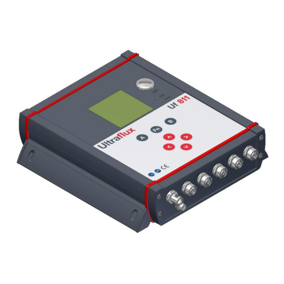
Uf 811 CO
(open channel)
User Manual
Bâtiment Texas – Éragny Parc
9, Allée Rosa Luxemburg
95610 ÉRAGNY SUR OISE, FRANCE
Tel.: 33 (0)1 30 27 27 30
Fax: 33 (0)1 30 39 84 34
Advertisement
Table of Contents

Subscribe to Our Youtube Channel
Related Manuals for Ultraflux Uf 811 CO


Summary of Contents for Ultraflux Uf 811 CO
- Page 1 Fax: 33 (0)1 30 39 84 34 2012 ULTRAFLUX S.A. All rights reserved. No part of this document may be reproduced without prior written authorisation from ULTRAFLUX S.A. ULTRAFLUX, Uf 811 are registered trademarks of ULTRAFLUX S.A. NT UF 811 CO GB (c) / March 2014...
-
Page 2: Table Of Contents
CHAPTER 3: INSTALLATION AND WIRING ___________________________ 14 3.1 Wall attachment _______________________________________________________________ 15 3.2 Wiring instructions _____________________________________________________________ 16 3.3 Connector wiring ______________________________________________________________ 16 3.4 Ground connection _____________________________________________________________ 27 3.5 Connection ___________________________________________________________________ 27 NT UF 811 CO GB (c) / March 2014... - Page 3 Appendix IV: Link protocol of the Uf 811 ____________________________ 95 IV.1 Serial link characteristics _______________________________________________________ 96 IV.2 Reading of N words (with N ≤ 125) _______________________________________________ 97 IV.3 Modbus / Jbus table ___________________________________________________________ 98 IV.4 CRC16 calculation algorithm ____________________________________________________ 102 NT UF 811 CO GB (c) / March 2014...
-
Page 4: Chapter 1: Overview
CHAPTER 1: OVERVIEW NT UF 811 CO GB (c) / March 2014... -
Page 5: Converter Overview
IP 67: Total protection against dust; protection against immersion for 30 minutes under 1m of water. This protection is only valid if the installation has been carried out or audited by Ultraflux. This protection is only ensured when the connectors are connected or capped (where the connector is not in use). -
Page 6: Power Supply
The connectors must only be connected or disconnected with the power off and the equipment isolated. If the flow meter unit is opened by anyone other than an Ultraflux technician, the warranty will be rendered null and void. ... -
Page 7: Inputs/Outputs
To scroll through the measurement screens, use the and keys. To access the other menus, press the "Fn" key, then successively press the key, or browse using the and keys. NT UF 811 CO GB (c) / March 2014... -
Page 8: Operating Lamps
Fixed red light when the flow calculation is faulty. 1.11 Screen LCD: graphic (14 rows x 20 characters). Backlighting: permanent or timed. Screen reading: from -20°C to +60°C. NT UF 811 CO GB (c) / March 2014... -
Page 9: Functions
In the context of decree no. 2005-829 dated 20 July 2005 relating to the collection, treatment and disposal of electrical and electronic equipment in France, Ultraflux delegates the responsibility for financial and also logistical recovery to the user, who will manage their own waste. -
Page 10: Ce Marking
Immunity to radiated electromagnetic fields Criterion A EN 61000-4-4 Immunity to rapid transients in bursts Criterion B EN 61000-4-5 Immunity to shock waves Criterion B EN 62311 Human exposure to electromagnetic fields NT UF 811 CO GB (c) / March 2014... -
Page 11: Chapter 2: Safety Instructions
CHAPTER 2: SAFETY INSTRUCTIONS NT UF 811 CO GB (c) / March 2014... -
Page 12: Using The Flow Meter
Should the temperature of the unit rise abnormally, it is recommended to power off the flow meter and call Ultraflux for expert advice. In the event of a fire inside the flow meter, power it off without opening or touching it, then call the competent services in order to secure the premises. -
Page 13: Contact Address
For any requests for information, please contact us at: ULTRAFLUX 9, Allée Rosa Luxemburg 95610 ERAGNY FRANCE http://www.ultraflux.net E-mail : ultraflux@ultraflux.fr Tel.: 33 (0)1 30 27 27 30 Fax: 33 (0)1 30 39 84 34 2012 ULTRAFLUX S.A. NT UF 811 CO GB (c) / March 2014... -
Page 14: Chapter 3: Installation And Wiring
CHAPTER 3: INSTALLATION AND WIRING NT UF 811 CO GB (c) / March 2014... -
Page 15: Wall Attachment
It is recommended to follow the assembly method described below in order to avoid any risk of injury. Assembly must be carried out or inspected by Ultraflux to ensure the unit is leakproof and will operate correctly. -
Page 16: Wiring Instructions
It is sometimes necessary to protect the inputs/outputs, the power supply and the ultrasonic chords. You are strongly recommended to contact Ultraflux to obtain a diagnosis on this point. Ultraflux accepts no responsibility in the event of the incorrect use of the flow meter, and in such cases, the Ultraflux guarantee would not be valid. -
Page 17: Communication Connector
RS 485 : B / RTx (+) RS 232 : Tx (Output Uf 811) RS 232 : Rx (Input Uf 811) GND ISO Note: the pin number is engraved directly on the connector. NT UF 811 CO GB (c) / March 2014... - Page 18 Fit the armour, the packing and the ring clip. Turn the set screw to fasten the cable in place. Screw down the conductor wires. Fit the connector. Firmly tighten the set screw. NT UF 811 CO GB (c) / March 2014...
-
Page 19: Input/Output Connectors
Location 3 pin 2 7 I/O 1 Location 1 pin 3 7 I/O 2 Location 3 pin 3 8 I/O 1 Location 1 pin 4 8 I/O 2 Location 3 pin 4 NT UF 811 CO GB (c) / March 2014... -
Page 20: Wiring Of The Relay Modules
A wire 2 current B wire 1 current B wire 2 4) Wiring of the voltage input modules The pins have the following functions: Function voltage A(+) voltage A(-) voltage B(+) voltage B(-) NT UF 811 CO GB (c) / March 2014... -
Page 21: Wiring Of The Temperature Modules
Important: For 2- or 3-wire cables, just use "bridging" to make up for the missing wires. In the 3-wire version, a white wire is missing: simply bridge the two white wire terminals 1 and 2, and place the white cable on the "white wire" pin. NT UF 811 CO GB (c) / March 2014... -
Page 22: Example Of A Module Configuration
5 I/O 2 red wire 1 probe 1 6 I/O 2 white wire 1 probe 1 7 I/O 2 red wire 2 probe 1 8 I/O 2 white wire 2 probe 1 NT UF 811 CO GB (c) / March 2014... -
Page 23: Plug Fitting Instructions
Fit the armour, the packing and the ring clip. Turn the set screw to fasten the cable in place. Screw down the conductor wires. Fit the connector. Firmly tighten the set screw. NT UF 811 CO GB (c) / March 2014... -
Page 24: Probe And Chord Connector
The flow meter may be configured with only one probe per connector, but the number of possible chords is then divided by two. You are recommended to contact Ultraflux in order to define the best configuration for your application. -
Page 25: Power Supply Connector
1. Install the protective grounding braid on the dedicated screw. 2. Install the V+, 0V and ground wires on the connector. NT UF 811 CO GB (c) / March 2014... - Page 26 Fit the armour, the packing and the ring clip. Turn the set screw to fasten the cable in place. Screw down the conductor wires. Fit the connector. Firmly tighten the set screw. NT UF 811 CO GB (c) / March 2014...
-
Page 27: Ground Connection
Screw the connector to the cable using the torque intended for the connector. Note: If a connection is not used, cap it off at the Uf 811 in order to maintain IP67 leaktightness NT UF 811 CO GB (c) / March 2014... -
Page 28: Chapter 4: Implementing A Measuring Point
CHAPTER 4: IMPLEMENTING A MEASURING POINT NT UF 811 CO GB (c) / March 2014... -
Page 29: Choosing The Measurement Location
There are 5 main steps to commissioning a measuring point and these must be followed very carefully. We would also like to remind you that Ultraflux can help with commissioning of your flow meters (for further information on this service, please contact us). -
Page 30: Measurements To Be Taken On Site
The distance between probes "L" The axis diameter 5. Produce the plan of the different heights: Of the water level gauge Of the velocity measurement chords (ultrasonic probes) Of the level sensors NT UF 811 CO GB (c) / March 2014... -
Page 31: Transferring The Data Collected To The Converter
All of the data collected previously (points 4.3 and 4.4) must be transferred to the converter. There are two ways you can do this: Using the PC software for your Uf 811 (see Chapter 7), Directly in your UF 811's interface (see Chapter 5). NT UF 811 CO GB (c) / March 2014... -
Page 32: Chapter 5: Using And Configuring The Uf 811
CHAPTER 5: USING AND CONFIGURING THE Uf 811 NT UF 811 CO GB (c) / March 2014... -
Page 33: Using The Uf 811
For a given parameter, the value to be applied is defined using the (up) and (down) keys. Pressing and holding one of these two keys accelerates the increase or decrease. NT UF 811 CO GB (c) / March 2014... -
Page 34: Main Configuration Elements
one or more ultrasonic chords, up to four level sensors (which may or may not be provided by Ultraflux). 2) Reference systems used Two reference systems are used: The customer reference system: the one used in measurement mode to display the water level. - Page 35 For rather complex sections (e.g. semi-circular outfall sewer with cunette), it is important to surround the discontinuities with two elevations close together. It is not compulsory to define 20 pairs of points. The widths of the unused points may be set to 0. NT UF 811 CO GB (c) / March 2014...
-
Page 36: Correspondence Between Customer Reference System And Section Description Reference System
the amplitude in the variation of the level (since the probes must be submerged in order to operate) For all of these technical points, consult Ultraflux if necessary. 5.2.2 Number of channels Note: for multi-channel flow meters only, it is possible to define the number of channels to be managed by the flow meter. -
Page 37: Configuring The Uf 811
ADVANCED SETTINGS: settings for the simulation mode, the special probes, the specific codes for ultrasonic treatment, etc. ECHO DISPLAY: display of the echo signals of the ultrasonic probes. FIRMWARE UPDATE: update the firmware. NT UF 811 CO GB (c) / March 2014... -
Page 38: Simple Configuration Mode
This command is used to reset the flow meter (restoration of factory settings). 3) Confirmation (of reset) The flow meter is reset via a field requiring confirmation (protection against handling errors). NT UF 811 CO GB (c) / March 2014... -
Page 39: Settings
Each flow meter can be assigned a label with up to 8 characters (registration number). The position of the current character is chosen using the ▼ and ▲ keys. To scroll through the characters, use the < and > keys. NT UF 811 CO GB (c) / March 2014... -
Page 40: Back Light
The flow meter automatically returns to the Measurement screens after approximately one minute. The modified settings will then be taken into account. This avoids the risk of forgetting to exit "Configuration" mode and needing to do further operations to return to "Measurement" mode. NT UF 811 CO GB (c) / March 2014... -
Page 41: Pipe/Fluid Settings" Menu
(in metres) between the faces of the two probes, the projected length (axis diameter) with regard to the axis of the channel or the river, the height compared to H0. NT UF 811 CO GB (c) / March 2014... -
Page 42: Section Description" Menu
If the value of S0 is negative, the value of S0 is deducted from the section and it is considered that so long as the wetted section is smaller than S0, the flow is null (silting). The aim is to simulate silting of the channel. NT UF 811 CO GB (c) / March 2014... -
Page 43: Level Settings" Menu
"Flow measurement by transit time difference"). The value of this coefficient may be fixed section by section (absolute mode) or may be calculated for each section based on the distance from the section to the surface. NT UF 811 CO GB (c) / March 2014... - Page 44 The deepest section is marked by the bottom of the channel or the river and by elevation no. 1, The sections describing the hydraulic profile are fully independent of the sections describing the measurement section. NT UF 811 CO GB (c) / March 2014...
-
Page 45: Choosing The Definition Mode Of The Hydraulic Profile
Starting with the lowest elevation (Pt1), specify for each section the upper elevation of the section and the corresponding hydraulic coefficient. Comments: The elevation of point no. 20 must be greater than the maximum foreseeable level, For a given section, the velocity must be roughly constant. NT UF 811 CO GB (c) / March 2014... -
Page 46: Relative Mode
When the level is below the lowest chord, the flow cannot be measured using ultrasound. It can however be estimated using a linear interpolation curve with 4 points, or by self-learning (automatic regression). Velocity Height NT UF 811 CO GB (c) / March 2014... - Page 47 The flow meter will then estimate what the height/velocity curve could be, taking into account the measuring points. A coefficient can then be defined which will be used until the flow meter takes new measurements. NT UF 811 CO GB (c) / March 2014...
-
Page 48: Totalizer Settings" Menu (If Activated)
(mutually agreed by both parties). Upon request and before dispatch, totalizer reset can be authorised. On site, only an Ultraflux representative will be able to reset the totalizers. To reset a totalizer (if authorised): 1. -
Page 49: Input/Output Settings" Menu (If Activated)
Relay. The menu only appears if inputs or outputs are installed on the flow meter. To install additional inputs/outputs, please contact Ultraflux to find out the specifications of all available inputs/outputs. 1) Current input and voltage input module The possible options are: ... -
Page 50: Temperature Input Module
The possible options are: OFF: deactivated, PT100-PT1000 mode 2-, 3- or 4-wire (for further details, contact Ultraflux). Define: the type of sensor, Pt 100 or Pt 1000, the type of assembly, 2-wire, 3-wire or 4-wire, the value of the filter and the memory, any offset. -
Page 51: Relay Output Module
We will therefore have 1 pulse every 100/1,000 = 100 ms The value of the period must not therefore be greater than 100 ms, at the risk of not counting all of the pulses emitted by the totalizer. NT UF 811 CO GB (c) / March 2014... - Page 52 (function) and the chapter items (value). the value corresponding to 0 Hz. the value corresponding to 1 kHz. the value in the event of a fault. NT UF 811 CO GB (c) / March 2014...
-
Page 53: Logger Settings" Menu (If Activated)
10 mins, 15 mins, 30 mins, 1 hr, 2 hrs, 6 hrs, 12 hrs and 24 hrs. 6) Logger autonomy This field cannot be edited and indicates the logger's remaining autonomy. NT UF 811 CO GB (c) / March 2014... -
Page 54: Logger Variables
Time (s) The vertical lines (blue) correspond to the triggering of records of the logger. If the variation of the flow is greater than the configured threshold, the logger forces a recording. NT UF 811 CO GB (c) / March 2014... -
Page 55: Echo Display" Menu
The measurement is taken the first time the alternation that crosses this threshold reaches 0. The ultrasound path duration delta is indicated in the bottom left hand corner (not taking into account the ∆ T0). NT UF 811 CO GB (c) / March 2014... -
Page 56: Normal Configuration Mode
The flow measurement is then given as faulty if there is still no new valid flow measurement. Time Configured storage time NT UF 811 CO GB (c) / March 2014... -
Page 57: Filter
20 seconds, give the time constant a value of 40 or 60 s. However, you must ensure that the time constant is not too large, since this would risk masking significant events. NT UF 811 CO GB (c) / March 2014... -
Page 58: Deletion Rate (Cutoff Q)
This minimum immersion depends on the frequency used and the length of the acoustic path. Comment: The immersion depth of the probes is counted from the central plane of a chord. NT UF 811 CO GB (c) / March 2014... -
Page 59: Advanced Configuration
Using the maximum gain parameter, you can limit the gain so that the unwanted acoustic noise does not disrupt the operation of the flow meter. Important: It is highly recommended to contact Ultraflux before modifying these settings. NT UF 811 CO GB (c) / March 2014... -
Page 60: Linearization Settings" Menu
0 and 2 times the indicated value. To simulate the level, go to the input/output settings and change the simulation value in the input corresponding to the level measurement (see chapter dedicated to inputs/outputs). NT UF 811 CO GB (c) / March 2014... -
Page 61: Special Probes
2) Special probes It may be necessary in certain cases to define a probe which is not referenced in the list of Ultraflux probes. Before using this option, it is highly recommended to contact Ultraflux. To use probes other than Ultraflux probes, use the "special probes" function. -
Page 62: Measurement" Mode
(the higher the gain, the more difficult it is to obtain a measurement), QI quality index (100% indicates a very good measurement, 0% indicates that the measurement is not possible). NT UF 811 CO GB (c) / March 2014... -
Page 63: Totalizers
This page indicates the status of the logger and the last recording made. 7) Events These pages are used to find out whether there is a problem on the flow meter and to localise it in order to resolve it. NT UF 811 CO GB (c) / March 2014... -
Page 64: Probe Type
The information on the different "Measurement" mode pages is used to check the consistency of your measurement. The gain and QI (quality index) values also tell you about the quality of your measurement. NT UF 811 CO GB (c) / March 2014... -
Page 65: Chapter 6: Function Engine
CHAPTER 6: FUNCTION ENGINE NT UF 811 CO GB (c) / March 2014... -
Page 66: Principle
6.1 Principle Each Uf 811 includes a miniature PLC. This PLC allows Ultraflux to easily install additional features for this flow meter. On request, Ultraflux can quickly integrate a new feature for your Uf 811. 6.2 Application example 6.2.1 Water temperature calculation The water temperature can be determined from its celerity (via a calculation). -
Page 67: Chapter 7: Pc Software
CHAPTER 7: PC SOFTWARE NT UF 811 CO GB (c) / March 2014... -
Page 68: Introduction
The program is run by double-clicking the icon associated with the software and placed on the desktop, or by selecting the program via Start \ Programs \ Ultraflux \ software corresponding to your flow meter. NT UF 811 CO GB (c) / March 2014... -
Page 69: Connecting The Flow Meter To The Pc
When run, the software displays the following window: This window contains four main menus: - "File", - "Dialogue", - "Options", - "About". First open the Options menu to define the settings relating to your application. NT UF 811 CO GB (c) / March 2014... -
Page 70: Options Window
(Excel by default, if this is installed on your computer). It also includes a "Autosearch" button used to automatically detect the presence of an Ultraflux flow meter. Comment: To use the serial link, the transmission speed can be set from 300 to 115,200 bauds, the fastest speed being preferable, especially for data-logger downloads. -
Page 71: File Menu
"Inputs/outputs" tab: contains general information about the inputs-outputs. "Function" tab (optional): contains settings information for the function engine if this is used (tab only appears if at least 1 engine output is configured) NT UF 811 CO GB (c) / March 2014... -
Page 72: General" Tab
2) "General" tab This tab displays the main measurement information: graph of the measurement, point value for the flow and the flow velocity, totalizers. NT UF 811 CO GB (c) / March 2014... -
Page 73: Qa" Tab (Flow Rate)
This tab displays the main information about the measurement channel: value of flow, flow velocity, section and height of water. It also provides information concerning the measurement chords. Comment: There are as many tabs as there are channels configured. NT UF 811 CO GB (c) / March 2014... -
Page 74: Input-Output" Tab
"Function" tab: definition of the engine input constants accessible to the user (when a function is located in the engine). "Advanced" tab: definition of the Advanced operating mode. "Inputs/outputs" tab: definition of the input/output settings (including the 4-20 mA inputs for the Level inputs). NT UF 811 CO GB (c) / March 2014... -
Page 75: General" Tab (In The "General" Drop-Down Menu)
PC: select the option "Synchronise with PC time" before saving the settings on the flow meter. It is important to correctly set the date and time in order to time stamp the records (country, summer/winter time). NT UF 811 CO GB (c) / March 2014... -
Page 76: Logger" Tab (In The "General" Drop-Down Menu)
4) "Totalizers" tab (in the "General" drop-down menu) The screenshot below shows an example of settings in Advanced mode. All of the parameters displayed below are described previously in this document (see part 5.4.7). NT UF 811 CO GB (c) / March 2014... -
Page 77: Inputs/Outputs" Tab (In The "General" Drop-Down Menu)
The screenshot below shows an example of settings in Advanced mode. All of the parameters displayed below are described previously in this document (see part 5.4.8). You can choose whether or not to activate the Totalizer, Logger and Input/Output functions resources. NT UF 811 CO GB (c) / March 2014... -
Page 78: Channel" Tab (In The "Channel" Drop-Down Menu)
7) "Chord" tab (in the "Channel" drop-down menu) The screenshot below shows an example of settings in Advanced mode. All of the parameters displayed below are described previously in this document (see part 5.4.2). NT UF 811 CO GB (c) / March 2014... -
Page 79: Section" Tab (In The "Channel" Drop-Down Menu)
The screenshot below shows an example of settings in Advanced mode. All of the parameters displayed below are described previously in this document (see part 5.4.3). These three buttons are used to define the sections of predefined shapes (rectangle/trapezium/circle) via a "wizard". NT UF 811 CO GB (c) / March 2014... -
Page 80: Hydraulic Profile" Tab (In The "Channel" Drop-Down Menu)
10) "Level" tab (in the "Channel" drop-down menu) The screenshot below shows an example of Advanced settings. All of the parameters displayed below are described previously in this document (see part 5.4.4). NT UF 811 CO GB (c) / March 2014... -
Page 81: Height/Velocity" Tab (In The "Channel" Drop-Down Menu)
12) "Linearisation" tab (in the "Channel" drop-down menu) The screenshot below shows an example of Advanced settings. All of the parameters displayed below are described previously in this document (see part 5.6.2). NT UF 811 CO GB (c) / March 2014... -
Page 82: Archiving, Processing And Printing Of Saved Files
The Uf 811 has 11 spaces in its free memory for the storage of configurations (see part 5.4.1): you can therefore recall or save your selections. Important: only the first 5 locations are accessible from the PC software, the other 6 may only be accessed via the converter. NT UF 811 CO GB (c) / March 2014... -
Page 83: Appendix I: Characteristic Echo Signals
Appendix I: Characteristic echo signals NT UF 811 CO GB (c) / March 2014... - Page 84 Comment: The signals observed are often longer than the one shown above. This is completely normal, the important criterion being the velocity of the signal rise above the threshold. Slowly rising signal: Signal distorted by an incorrect positioning of the probes: NT UF 811 CO GB (c) / March 2014...
- Page 85 (pollution on the surface of the probe). Presence of electromagnetic interference Comment: in this case, move the cables (in particular the probe cables) away from the power cables. Check the ground connections and the shielding. NT UF 811 CO GB (c) / March 2014...
-
Page 86: Appendix Ii: Speed Of Sound In Water
Appendix II: Speed of sound in water NT UF 811 CO GB (c) / March 2014... - Page 87 (°C) C (m/s) t (°C) C (m/s) 1422.8. 1506.4. 1426.5. 1520.1. 1447.6. 1529.2. 1466.3. 1536.7. 1482.7. 1542.9. 1497 — — Approximate value: C = 1557 – 0.0245.(74 – t)2 Celerity (m/s) Temperature (C°) NT UF 811 CO GB (c) / March 2014...
-
Page 88: Appendix Iii Troubleshooting
Appendix III Troubleshooting III.1 Diagnostic indications III.2 Description of fault bits III.3 Fault grid NT UF 811 CO GB (c) / March 2014... -
Page 89: Iii.1 Diagnostic Indications
Probes misaligned, Probes clogged, Fluid absorbent, or slurry, or aerated. Comment: A simple way of masking intermittent measurement faults and increasing the memory storage time (see section 5.5.1). NT UF 811 CO GB (c) / March 2014... - Page 90 The message "open loop" appears permanently when setting a current output Cause: Break in the loop. The message "outside limits" appears permanently or intermittently when setting an analogue input Cause: Current or voltage outside the range of use. NT UF 811 CO GB (c) / March 2014...
-
Page 91: Iii.2 Description Of Fault Bits
Fault on an input/output module. Internal clock The clock time must be set correctly. Fault on the Qb pipe. Fault on the Qa pipe. Fault on the total flow. QT not valid Total flow invalid. NT UF 811 CO GB (c) / March 2014... - Page 92 Voltage A input value The measurement of voltage A is outside the authorized range. outside range Voltage B input value The measurement of voltage B is outside the authorized range. outside range NT UF 811 CO GB (c) / March 2014...
- Page 93 Flow calculation Chord taken into account in the flow calculation. Fault Fault on a chord. Not valid Chord not valid. Function fault BIT No. FUNCTION NAME DESCRIPTION Fault Function output fault. NT UF 811 CO GB (c) / March 2014...
-
Page 94: Iii.3 Fault Grid
The non-volatile memory is faulty; measurement is possible but not archiving by the logger. Contact Ultraflux. logger The logger data cannot be used or is corrupt. Contact Ultraflux. h/w I/O One of the inputs/outputs is no longer responding. Contact Ultraflux. -
Page 95: Appendix Iv: Link Protocol Of The Uf 811
Appendix IV: Link protocol of the Uf 811 IV.1 Serial link characteristics IV.2 Reading of N words (with N ≤ 125) IV.3 Modbus/Jbus table IV.4 CRC16 calculation algorithm NT UF 811 CO GB (c) / March 2014... -
Page 96: Iv.1 Serial Link Characteristics
For FLOAT type information, it must be possible to read two consecutive words (or 4 bytes). The format complies with the IEEE standard. For LONG type information, two consecutive words (or 4 bytes) must be read. NT UF 811 CO GB (c) / March 2014... -
Page 97: Iv.2 Reading Of N Words (With N ≤ 125)
2 bytes Response Data Slave no. number of bytes read value 1st word ….. value last word CRC16 Size 1 byte 1 byte 1 byte 2 bytes ….. 2 bytes 2 bytes NT UF 811 CO GB (c) / March 2014... -
Page 98: Iv.3 Modbus / Jbus Table
Height / Channel Description Point (2) FLOAT 0231 0431 1073 Water Height (2) FLOAT 0233 0433 1075 Water Height Max. Delta (2) FLOAT 0235 0435 1077 Fault ULONG 0237 0437 1079 0239 0439 1081 NT UF 811 CO GB (c) / March 2014... - Page 99 1135 Gain FLOAT 0271 0471 1137 FLOAT 0273 0473 1139 Fault ULONG 0275 0475 1141 Probe Reference USHORT 0277 0477 1143 Distance Between Probes USHORT 0278 0478 1144 0279 0479 1145 NT UF 811 CO GB (c) / March 2014...
- Page 100 Value FLOAT 02E1 04E1 1249 Fault ULONG 02E3 04E3 1251 02E5 04E5 1253 IO 04B 02E5 04E5 1253 Value FLOAT 02E5 04E5 1253 Fault ULONG 02E7 04E7 1255 02E9 04E9 1257 NT UF 811 CO GB (c) / March 2014...
- Page 101 0539 1337 Value FLOAT 0339 0539 1337 Fault ULONG 033B 053B 1339 033D 053D 1341 Function output 10 033D 053D 1341 Value FLOAT 033D 053D 1341 Fault ULONG 033F 053F 1343 NT UF 811 CO GB (c) / March 2014...
-
Page 102: Iv.4 Crc16 Calculation Algorithm
= number of bits poly = calculation polynomial of CRC16 = 1010 0000 0000 0001 (generator polynomial = 2 X the first byte sent is the one with the least significant bits NT UF 811 CO GB (c) / March 2014... - Page 103 6) Example of a module configuration __________________________________________________ 22 7) Plug fitting instructions ___________________________________________________________ 23 3.3.3 Probe and chord connector ____________________________________________ 24 3.3.4 Power supply connector ______________________________________________ 25 3.4 Ground connection _____________________________________________________________ 27 3.5 Connection ___________________________________________________________________ 27 NT UF 811 CO GB (c) / March 2014...
- Page 104 5.4.5 "Hydraulic Profile" menu _____________________________________________ 43 1) Description of the hydraulic profile __________________________________________________ 43 2) Choosing the definition mode of the hydraulic profile ___________________________________ 45 3) Absolute mode __________________________________________________________________ 45 4) Relative mode ___________________________________________________________________ 46 NT UF 811 CO GB (c) / March 2014...
- Page 105 5) Date and time ___________________________________________________________________ 63 6) Logger info _____________________________________________________________________ 63 7) Events _________________________________________________________________________ 63 8) Probe type _____________________________________________________________________ 64 9) Flow graph _____________________________________________________________________ 64 5.7.2 Verification of measurement quality and consistency ________________________ 64 NT UF 811 CO GB (c) / March 2014...
- Page 106 Appendix IV: Link protocol of the Uf 811 ____________________________ 95 IV.1 Serial link characteristics _______________________________________________________ 96 IV.2 Reading of N words (with N ≤ 125) _______________________________________________ 97 IV.3 Modbus / Jbus table ___________________________________________________________ 98 IV.4 CRC16 calculation algorithm ____________________________________________________ 102 NT UF 811 CO GB (c) / March 2014...
Need help?
Do you have a question about the Uf 811 CO and is the answer not in the manual?
Questions and answers
Bu cihazların kullanıcı adı ve şifresi nedir