Table of Contents
Advertisement
Advertisement
Table of Contents

Related Manuals for Ultraflux Minisonic Series


Summary of Contents for Ultraflux Minisonic Series
- Page 1 Bâtiment TEXAS Éragny Parc 9, Allée Rosa Luxemburg 95610 ÉRAGNY, FRANCE Tél : 33 (0)1 30 27 27 30 Fax : 33 (0)1 30 39 84 34 www.ultraflux.net Ultraflux NT 217C GB1 Edition : 29/04/2013 NT217 C GB1 1 / 27...
- Page 2 PREAMBLE: Thank you for choosing Ultraflux to make your flow measurement. We offer a full range of portable or fixed flowmeters backed by 30 years’ expertise and experience using Ultrasonic techniques: UF 801-P family, high features portable flow meters, with integral loggers and signal analysis functions.
-
Page 3: Table Of Contents
SUMMARY: 1 – Typical Applications: Liquid flow measurements and controls Clamp on or insertion transducers 2 – Composition of a measurement point. Certifications Applicable standards MiniSonic limitations Recommended accessories 3 – Ergonomics and dimensions Industrial wall mounting version Ex d, CE ATEX certified version 4 –... -
Page 4: Typical Applications
The external probe (SE) solution is possible with most fluids circulating through metal or plastic pipes. Ultraflux offers a wide range of probes distributed in terms of frequency and signs to suit a multitude of applications on inside pipe diameters ranging from 10 mm to more than 3 meters. - Page 5 1-1 – Principle of measurement: The principle of measurement is detailed and commented on in our training manual NT 106. To summarize, note that it bears on the velocity difference (and therefore the ultrasound wave transit times) in a moving medium, depending on whether the movement is with or against the current.
- Page 6 1-3 – Speed of sound in fluids – Relation with density – Influence of P and T: The speed of sound in a fluid is a full-fledged physical characteristic which may be linked with others, such as density (d), pressure (P), temperature (T) or the % of two or several miscible products or with another magnitude having good analogy, like compressibility.
- Page 7 Superheated water involves curve or graph networks taking into consideration the pressure and the temperature: consult us. Measurement on petroleum products – values at 15°C / 1 bar (except for butane and propane): 1500 Water 1400 Domestic fuel oil Gas Oil Xylene Kerosene HT Benzene...
-
Page 8: Composition Of A Measurement Point
2 - COMPOSITION OF A MEASUREMENT POINT - The two probes - The integrated or optional supports (SU - The coupling kit if external clamp-on probes. - Integral or optional supports (SU) - Probe / converter link cables - MiniSonic converter. - PC / converter link cable and software (CD-ROM). -
Page 9: Ergonomics And Dimensions
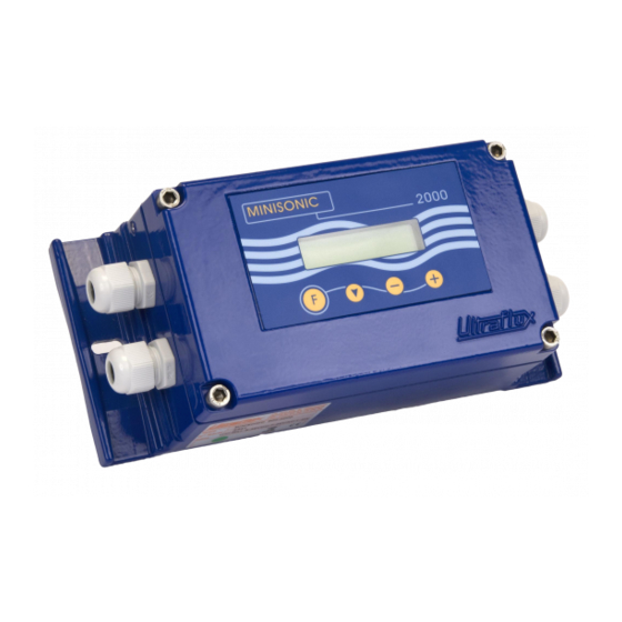
3 – ERGONOMICS AND DIMENSIONS OF MINI 600 & 2000 CONVERTERS 3-1: Industrial version for wall mounting (IP 67) The two stuffing boxes on the left-hand side are for the supply (top) and the outlets. The two stuffing boxes on the right are for probe cables. To open the MiniSonic *(cabling or other), undo the four corner screws and remove the cover by disconnecting the flat interconnection cable from the display on the display side. - Page 10 3-2 : Ex d CE ATEX Version (Ex d IIC T6) – IP 67: > See also NT 219-B - The keypad keys have the same functions as for the industrial version. - The two stuffing boxes on the porthole side are reserved for cables to the probes. - To carry out the internal cabling of the probe cables on the MiniSonic card, it is necessary to pull the support rack forwards: remove the three front panel screws.
- Page 11 4 – MINISONIC 600 & 2000 WIRING PLAN: (Low Voltage Supply) If the GP 01 Module for 90 to 230 V AC Supply is installed, see also NT 218 - Internal cables must be kept as short as possible. Cables are to enter through the stuffing box facing the terminals.
- Page 12 Attention! If this R loop is too high for the supply, the curent fall down to 4 mA Connection of two probes: BR 4 (BR 3 is reserved for the dual-channel versions) - Use preferably the twin-ax cables (ET1217) specified by Ultraflux. - For armoured cable (ET1217A), stop the foil wrap before or inside the gland.
-
Page 13: Probes Installation
– General Procedures. 6- PROBES INSTALLATION The MiniSonic 600 & 2000 accept all standard or special transducers of Ultraflux catalogue with frequency from 250 KHz up to 2 MHz: clamp-on, insertion or wetted… Unless specified and instructed otherwise in the order, refer to the probe data sheet >... - Page 14 Probes installation : particular recommendations for a portable use Please read general recommendations as detailed in our training manual NT 122. Under header §2, we give some information about expected accuracy depending on available straight length and transducers mounting modes. When you will arrive in front a new pipe to be measured, you must have some good reflex, and your experience will help for.
-
Page 15: Measurement Display Menu
7 - COMMISSIONING AND PARAMETERING OF MINISONIC 600 & 2000 1. Once the cabling has been carried out and verified, power up the system: > The MiniSonic must display its home screens: - Hardware version = MiniSonic 600 or 2000 or Ex d (2000) - Firmware version = 18.10-01 (e.g. - Page 16 8 - DETAILED REVIEW OF MENUS – MiniSonic Versions 600 and 2000 (+ Ex d) Here below we list the different menus with values and data as displayed by the LCD and what it is allowed to modify to do the setting. At the end of the chapter, we list some other functions or menu, which require the use of our LS_600W software on a PC.
-
Page 17: Calibration Allowed Menu
It will be required for any subsequent intervention. > In case of loss, contact Ultraflux giving the following informations ; the serial number of your MiniSonic MK4*/xx/xx/xxxx as it appears during energizing and the date or dates on which you want action to take place. An operation will be requested allowing a provisional code to be calculated. - Page 18 8-4: « Q Settings » menu ( Flow / Fluid ) Q unit = m ∇ Choice of Flow unit: ( l/h …tot … m3/s ); ∇ Qmax (unit) Scale (graphics on PC only): +/xxxxx.x Outputs: see menu « General » ∇...
- Page 19 8-5: « Probe / Echo parameter settings » menu : ∇ Probe = SE xxxx Choice of probe: (or SM ou SP. A/B) From this choice, it results Emitting Frequency, D.S. calculation (S.E.) or Opening of L and D fields (SM) ∇...
- Page 20 8-6: « General Settings » menu ∇ Back Light Setting of LCD backlighting ON / OFF / TIMED (Depending on MiniSonic version) ∇ Filter = ∗∗ Filter rate of measurements (Number of 0.5 s cycles) ∇ Mémory (s)= ∗∗ Last accepted measure (IQ > 33%) Memorising time: (Mode ESC: enter Mém.
-
Page 21: Factory Settings Menu
! Caution = to carry out Self-zeroing, the flow rate must be absolutely zero while the display indicates « * dTo * ». 8-8: « Output Current Settings» menu ( normally reserved to Ultraflux ) It permits adjustment of coefficients 4 mA ( 1 &... - Page 22 8-11: Additional adjustments possible using PC + Software only The recommended values or states are entered by Ultraflux during testing before delivery. However, it may be necessary to modify them to adjust them to the site. If most of the operations can be performed from the keyboard, some call for the LS_600W (be sure to choose the right version).
- Page 23 Each application has its priorities. Accordingly, the MiniSonic is particularly flexible and can be adapted to extreme situations, meaning that many applications are possible. Ultraflux fills in each value or text field before the final tests and delivery. Nevertheless, it is advisable to verify them by running through the various menus, comparing them with files given at the time of order, or with your instructions or particular choices.
- Page 24 If the MiniSonic displays INIT constantly, attempt a power cutoff, then re-energize Would the MiniSonic supplied by a too low voltage or power source? If the fault persists, contact Ultraflux (Problem with the microprocessor). If the MiniSonic displays “Flow Rate Fault”, this message does not mean that the MiniSonic has failed, but that the ultrasound signals have not reached the expected level or are outside the window [Co +/- Delta C].
- Page 25 This device permits also ultrasonic thickness gauge option. Or measuring instruments for dimensional or alignment measurements SPARE PARTS: Ultraflux offers possibilities of purchasing spare cards or, as long as acceptance is granted, the standard replacement of equipment in the event of failure. ...
-
Page 26: Appendix
11 – APPENDIX 1 : Calibration file example of a MiniSonic- with clamp-on probes SE NT217 C GB1 26 / 27... - Page 27 2 – Calibration file example of a MiniSonic with SM insertion transducers : NT217 C GB1 27 / 27...
Need help?
Do you have a question about the Minisonic Series and is the answer not in the manual?
Questions and answers