Table of Contents
Advertisement
Ultraflux NT 208D GB 1
Révision : 29/04/2013
NT 208D GB1
User Manual
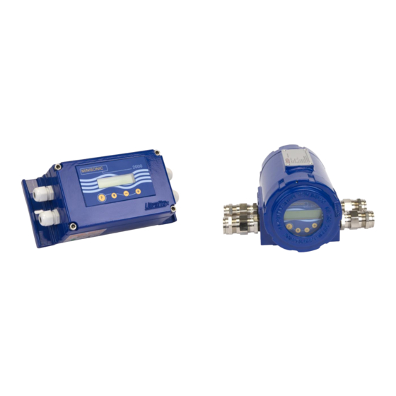
Minisonic 600 dual chord
(Minisonic_600-2)
Minisonic 2000 dual chord
(Minisonic_2000-2)
Bâtiment TEXAS
Éragny Parc
9, Allée Rosa Luxemburg
95610 ÉRAGNY, FRANCE
Tél : 33 (0)1 30 27 27 30
Fax : 33 (0)1 30 39 84 34
www.ultraflux.net
1 / 20
Advertisement
Table of Contents

Related Manuals for Ultraflux Minisonic_600-2


Summary of Contents for Ultraflux Minisonic_600-2
- Page 1 Éragny Parc 9, Allée Rosa Luxemburg 95610 ÉRAGNY, FRANCE Tél : 33 (0)1 30 27 27 30 Fax : 33 (0)1 30 39 84 34 www.ultraflux.net Ultraflux NT 208D GB 1 Révision : 29/04/2013 NT 208D GB1 1 / 20...
- Page 2 PREAMBLE : Thank you for choosing Ultraflux to make your flow measurement. We offer a full range of portable or fixed flowmeters backed by 30 years’ expertise and experience using Ultrasonic techniques: UF 801-P family, high features portable flow meters, with integral loggers, signal analysis functions and many options.
-
Page 3: Table Of Contents
SUMMARY: 1 – Typical Applications: Installation with intrusive (Wetted) probes on two parallel chords. Installation with clamp on probes on crossed diametric planes. 2 – Composition of a measurement point. Certifications Applicable standards MiniSonic limitations 3 – Ergonomics and dimensions Wall mounted industrial Version. -
Page 4: Typical Applications
1 - TYPICAL APPLICATIONS Compared to a single-chord version, the management of 2 chords placed correctly on the same pipe provides better monitoring for the hydraulic conditions specific to the site and are the key to better accuracy. There are two main possible acquisition configurations: ... -
Page 5: Composition Of A Measurement Point
2 - COMPOSITION OF A MEASUREMENT POINT - The probes (x4) are arranged two per chord - Integral or optional supports (SU) - Coupling kits for external probes - Probe / converter link cables - The converter associated with its accessories (software, PC cable) - If required, accessory modules: power supply transformer, Zener barriers CERTIFICATIONS All equipment is CE certified. -
Page 6: Ergonomics And Dimensions
3 - ERGONOMICS AND DIMENSIONS OF THE MINI 600 / 2000-2 CONVERTERS Wall-mounted industrial version (IP 65 or 67): The resources for cabling the 4 cables leading to the probes are provided by the installation of double glands on a “Y” type with IP 65 protection level. To preserve the MiniSonic index 67, an external extension box is necessary (optional supply). -
Page 7: Wiring Diagram
4 – WIRING DIAGRAM FOR MINISONIC 600-2 & 2000-2 : (Low voltage supply) (See also NT 218 if the GP 01 / 90-230 V AC // 24 V DC if installed). The internal cables must be kept as short as possible. The cable connections must use the adjacent gland. - Page 8 Attention! If this R loop is too high for the supply, the curent fall down to 4 mA Connection to probes: BR 4 (chord 1) & BR 3 (chord 2). - Use Twin-ax cables specified by Ultraflux (ET1217 & ET1217A). - In the industrial version, shield and conductors are separated in the “Y” compartment of the Y gland, while leaving a free length of 10 cm to terminal blocks.
-
Page 9: Probes Installation
6 – PROBES INSTALLATION – (General Procedures). Unless specified and instructed otherwise in the order, refer to the probe data sheet of the model used. A dual-chord spool must always be constructed according to our guide drawing. Once the structure has been made, verify the sizes “D ”... -
Page 10: Measurement Display Menu
7 - COMMISSIONING AND PARAMETERING OF MINISONIC 600-2 / 2000-2 1. Once the cabling has been carried out and verified, power up the system: The MiniSonic must display its delivered configuration screens: - Hardware version = MiniSonic 600-2 or 2000-2 and P.C. Board (MK4_M…) - Software version = 18.10-01 (e.g. - Page 11 8 – DETAILED REVIEW OF MENUS – MiniSonic Versions 600-2 and 2000-2 8 -1 : “ Measurement Display ” menu: Every time you return to this menu, MiniSonic displays : Probe = SE xxxx D.S. = xxxx mm chosen probes and inter-probe distance D.S.( if S.E. ) Q = xxx.xx m3/h Then Flow rate (or other choice as first screen) Seek Echo , Fault Q...
-
Page 12: Calibration Allowed Menu
It will be required for any subsequent intervention. In case of loss, contact Ultraflux giving the following information: the serial number of your MiniSonic MK4*/xx/xx/xxxx as it appears during energizing and the date or dates on which you want action to take place. An operation will be requested allowing a provisional code to be calculated. - Page 13 8-4 : « Q Settings » menu ( Flow / Fluid ) Q unit = m ∇ Choice of Flow unit: ( l/h …tot … m3/s ); ∇ Qmax (unit) Scale (graphics on PC only) : +/xxxxx.x Outputs: see menu « General » ∇...
- Page 14 8-5 : « Probe / Echo parameter settings » menu : ∇ Nb. Of Chords For two chords: ∇ Probe = SM xxxx Choice of probe: (or SE ou SP. A/B) Same choice for the 2 chords ∇ If SE (External probes) Probe mounting = V ( ou / , N , W ) / = single traverse...
- Page 15 8-6 : « General Settings » menu ∇ Back Light Setting of LCD back-lighting ON / OFF / TIMED (Depending on MiniSonic version) ∇ Filter = ∗∗ Filter rate of measurements (Number of 0.5 s cycles) ∇ Mémory (s)= ∗∗ Last accepted measure (IQ >...
- Page 16 ! Caution = to carry out Self-zeroing, the flow rate must be absolutely zero while the display indicates « * dTo 1 ou dTo 2*». 8-8 : « Output Current Settings» menu ( normally reserved to Ultraflux) It permits adjustment of coefficients 4 mA ( 1 &...
-
Page 17: General Parameters Menu
Each value or text field is filled in by Ultraflux before the final tests and delivery. Nevertheless, it is advisable to verify them by running through the various menus, comparing them with files given at the time of order, or with your instructions or particular choices. - Page 18 If the MiniSonic displays INIT constantly, attempt a power cutoff, then re-energize. If the fault persists, contact Ultraflux (Problem with the microprocessor). If the fault disappears, it may come back and could be due to excessively high impedance in the supply source.
- Page 19 Or a MiniSonic P or a DigiSonic E / P or an UF 810-P portable flowmeter. Or measuring instruments for dimensional or alignment measurements SPARE PARTS: Ultraflux offers possibilities of purchasing spare cards or, as long as acceptance is granted, the standard replacement of equipment in the event of failure. ...
-
Page 20: Appendix
11 – APPENDIX Calibration file example with a MiniSonic 2000-2 on a flow spool with wetted probes SM NT 208D GB1 20 / 20...
Need help?
Do you have a question about the Minisonic_600-2 and is the answer not in the manual?
Questions and answers