Table of Contents
Advertisement
Quick Links
Service Manual
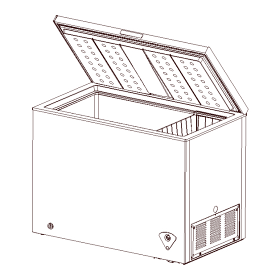
(The picture in this service manual is only for reference, and specific appearance and configuration are
subject to the real product)
CHEST FREEZER SERIES
1
Service Manual_2018-V1.0
Applicable Models
UR-BD199-DQ
Prepared by
R&D: Huang Yanmin
QA:WuXinbin
Reviewed by
SVC:Zhang Kun
R&D:ZhangHuawei
Approved by
SVC:GuangTaoshuai
Model Code
22032010003263
Advertisement
Table of Contents

Related Manuals for Midea UR-BD199-DQ


Summary of Contents for Midea UR-BD199-DQ
- Page 1 Service Manual_2018-V1.0 Service Manual CHEST FREEZER SERIES Applicable Models Model Code UR-BD199-DQ 22032010003263 Prepared by R&D: Huang Yanmin QA:WuXinbin Reviewed by SVC:Zhang Kun R&D:ZhangHuawei Approved by SVC:GuangTaoshuai (The picture in this service manual is only for reference, and specific appearance and configuration are...
- Page 2 Manufacturers or distributors are not responsible for the content of the Manual and interpretation thereof. Midea Refrigerators Technical Maintenance Manual Copyright @2017 All rights reserved. Replication of all or part of the Manual in any forms shall not be allowed without written approval by the Overseas Sales Corporation of Midea Refrigerators.
-
Page 3: Table Of Contents
Service Manual_2018-V1.0 Contents 1. Safety Warning Code ............................5 1.1 Warning for operation safety ........................5 1.2 Safety instruction for refrigerant ....................... 7 2. Description for product features ......................... 8 3. Installation and commissioning .......................... 9 3.1 Handling ............................... 9 3.2 Door Disassembly and Assembly ...................... - Page 4 Service Manual_2018-V1.0 10. Circuit description ............................. 29 10.1 Power Supply(None) ..........................29 10.2 Test circuit for door switch(None) ......................29 10.3 Temperature test circuit(None) ......................29 10.4 Freezer chamber fan motor circuit (None) ..................29 10.5 refrigerating chamber fan motor circuit (None) .................. 29 10.6 Condensation fan circuit (None) ......................
-
Page 5: Safety Warning Code
Service Manual_2018-V1.0 1. Safety Warning Code 1.1 Warning for operation safety Important Safety Instructions CAUTION RISK OF ELECTRIC SHOCK DO NOT OPEN This symbol indicates that dangerous voltage constituting a risk of electric shock is present within your freezer. This symbol indicates that there are important operating and maintenance instructions in the literature accompanying your freezer. - Page 6 Service Manual_2018-V1.0 CONNECTING ELECTRICITY Electrical Shock Hazard. Failure to follow these instructions can Plug into a grounded 3-prong outlet. result in death, fire, or electrical shock. Do not remove the ground prong. Do not use an adapter. WARNING Electric Shock Hazard Failure to follow these instructions can result in electric shock, fire, or death.
-
Page 7: Safety Instruction For Refrigerant
Service Manual_2018-V1.0 13) Do not store or use gasoline or any flammable liquids inside or in the vicinity of this freezer. 14) Do not use extension cords or ungrounded (two-prong) adapters with this freezer. If the power cord is too short, have a qualified electrician install an outlet near the freezer. Use of an extension cord can negatively affect the freezer’s performance. -
Page 8: Description For Product Features
Service Manual_2018-V1.0 2. Description for product features This product is provided with following features: 1) Fan-shaped temperature control panel with kitchen cabinet of complete freezing type 2) top single opening design... -
Page 9: Installation And Commissioning
Service Manual_2018-V1.0 3. Installation and commissioning 3.1 Handling Handling 1)Protect the refrigerator in moving it,Same as shown as left photo, please move it by handcart with cushion 2)Remove all packing materials and bottom cushion, the n move into house for placement 3)After moving it to appropriate location, wait for 2 hours before power on. -
Page 10: Leveling Of The Refrigerator
Service Manual_2018-V1.0 3.4 Leveling of the refrigerator Leveling of the refrigerator If the refrigerator cannot be placed steadily, adjust the footing to level it. 3.5 Door reversal Door reversal Door reversal None 3.6 Installation of handle Installation of handle 1- Handle 2- M5*14 screw(two) 3- Screw hole cover (two) 1) The handle is inserted below the display control board... -
Page 11: Installation Of Door Lock
Service Manual_2018-V1.0 3.7 Installation of door lock Installation of door lock Installation of door lock With the door handle together 3.8 Adjustment to level the door Adjustment to level the door Adjustment to level the door None 3.9 Adjustment to shelves Adjustment to shelves Adjustment to shelves None... -
Page 12: Terms
Service Manual_2018-V1.0 4. Terms 4.1 Definition of model (None) 4.2 Location of nameplate (None) -
Page 13: Product Specification
Service Manual_2018-V1.0 5. Product specification 5.1 Type specification (None) 5.2 Electrical parameters UR-BD199-DQ None Product Name Product Code 22032010003263 None Item Specification Specification Compressor Compressor FZ59E1G None QP2-4R7 None Starter(PTC) Overload protector(OLP) DRB29T61A1 None Rmc:7.02-8.08Ω Winding resistance of compressor wiring Rsc:8.88-10.22Ω... -
Page 14: Defrosting Parts
Service Manual_2018-V1.0 5.4 Defrosting parts Item Initial defrosting period Normal defrosting period Defrosting period None None Defrosting sensor None None Defrosting temperature None None controller Thermal fuse None None Defrosting heater in freezing None None chamber 5.5 Circuit diagram... -
Page 15: Internal View And Dimension
Service Manual_2018-V1.0 6. Internal view and dimension 6.1 Main parts and their names Freezer chamber Freezer chamber ❶ Door shell ❼ Levelling feet ❷ The door end cover ❽ Compressor mounting panel ❸ Door gasket ❾ Temperature-control panel ❹ Door liner ❿... -
Page 16: External Dimension
Service Manual_2018-V1.0 6.2 External dimension Description Code Size (mm) Size (mm) Height to Top of Case None Width None Depth/Hinge None Depth None Height (Door open) 1330 None... -
Page 17: Refrigerating Piping System And Circulating Route Of Cooling Air
Service Manual_2018-V1.0 7. Refrigerating piping system and circulating route of cooling air 7.1 Refrigerating piping system UR-BD100-DQ_ 22032010003261 ❶Compressor→❷Right condenser→❸Left Condenser→❹Dry filter→❺Capillary tube→❻Evaporator 7.2 Circulating route of cooling air... -
Page 18: Dismantling Of Parts
Service Manual_2018-V1.0 8. Dismantling of parts 8.1 Parts on the door Door seal 1)Pull the door seal from the corner 2)Take efforts until door seal totally detaches from door inner liner groove, remove the door seal 3)Fixing the four corners and pressing smoothly. The hinge cover Open the upper hinge of the lower hinge cover by hand to a certain angle until the hinge cover is separated... -
Page 19: Parts Inside The Refrigerator
Service Manual_2018-V1.0 Open the slanted upward of hinge cover to a certain angle by a screwdriver and remove the hinge cover. Wear safety gloves for fear of cutting the hand. When the door is closed, open the lower hinge cover along the side wall to a suitable angle and push forwards into the side wall of the hinge until the hinge cover boss completely falls into the hinge hole. -
Page 20: Light System
Service Manual_2018-V1.0 Counterclockwise to remove the pipe cover Ice tray Ice tray None 8.3 Light system Light Light None Light switch Light switch None Indicator lamp Indicator lamp None 8.4 Evaporator and temperature sensing system Freezer sensor Freezer sensor None Ambient temperature sensor Ambient temperature sensor None... - Page 21 Service Manual_2018-V1.0 Pull down the screw, open the shutter. Compressor and the cooling system pipe 1) Cut off the compressor pipeline.-❶Cut off the process pipeline.-❷Cut off the low-pressure muffler.-❸Cut off the high-pressure exhaust pipe. 2-1)Remove the screws(for some models) -Two screws outside -One screw inside 2-2)Remove the metal clamp(for some models) -Disassembly the metal clamp that is fix the electric...
- Page 22 Service Manual_2018-V1.0 4)Remove the protective cover -Pry the protective cover slowly from the upper part, -Pull it out and remove it. 5)Remove the starter and protector Unplug the starter and protector (you can use a screwdriver to pry it slowly) 6)Loosen the screw of the compressor bottom plate, remove the floor together with the compressor from the box.
- Page 23 Service Manual_2018-V1.0 8)Use Pipe cutter cut off the condenser tube❽, then Shear off capillary ❾ by the capillary tube scissors. 9)Replace the compressorand welding the compressor pipeline.-❿Welding the process pipeline.-⓫Welding the low-pressure muffler.-⓬Welding the high-pressure exhaust pipe. 10)Replace the filter, Cu-Fe tubes welding ⓭ used Ag welding rod, Cu-Cu tubes welding ⓮...
-
Page 24: Temperature-Control Box Assembly View
Service Manual_2018-V1.0 13)Use the vise grip pliers clamp the middle of the process pipe, then seal welding process tube⓯⓰. Piping system in the compressor case ❶ Capacitor ❿ Compressor ❷ -1 Front condenser pipeline-1 ⓫ Suction Pipe ❸ -2 Rear condenser pipeline-2 ⓬... - Page 25 Service Manual_2018-V1.0 ❶ screw ❹ Temperature-control panel ❷ Temperature-control box ❺ TEMP. control knob ❸ Thermostat ❻ Indicator light Destuffing 1) Pull down the screw, open the shutter. 2) Pull out the temperature probe from the temperature tube 3)Hold two tabs on the back cover of temperature-control box to remove the components 4)Use screwdriver to remove the two screws...
- Page 26 Service Manual_2018-V1.0 5)Separate the temperature-control box from the panel 6)Pull out the control knob 7)Pull out the fixed nut of the thermostat 8) Pull out the wiring harness and indicator light。remove the indicator light and thermostat, the reverse operation is for assembly...
-
Page 27: Function And Operation
Service Manual_2018-V1.0 9. Function and operation 9.1 Operation panel Icons Button ❶ Indicator hole cover/Power indicator Ⓐ freezer gear Ⓑ “OFF” 9.2 Temperature control Control panel without indicator light 1. Connect the freezer to power supply; 2. The interior temperature of the freezer is adjusted through the thermostat knob. Clock wisely rotate the thermostat knob and the interior temperature will drop.“MIN”is the warmest setting, “MAX”is the coldest setting. - Page 28 Service Manual_2018-V1.0 used to the accelerate de-icing process. Please remove the food and put in a cool place when defrosting before removing accessories.
-
Page 29: Circuit Description
Service Manual_2018-V1.0 10. Circuit description 10.1 Power Supply(None) 10.2 Test circuit for door switch(None) 10.3 Temperature test circuit(None) 10.4 Freezer chamber fan motor circuit (None) 10.5 refrigerating chamber fan motor circuit (None) 10.6 Condensation fan circuit (None) 10.7 Fan motor circuit of the ventilation door(None) 10.8 Resistance value of the sensor (R/T) (None) -
Page 30: Troubleshooting Method
Service Manual_2018-V1.0 11. Troubleshooting Method 11.1 Not cooling... -
Page 31: Not Working Of Compressor
Service Manual_2018-V1.0 11.2 Not working of compressor 11.3 Thermostat malfunction-Undercooling... -
Page 32: Light Is Not On
Service Manual_2018-V1.0 11.4 Light is not on 11.5 Noise... -
Page 33: Figures And Details Of Repair Parts(Documents Are Provided Separately)
Service Manual_2018-V1.0 12. Figures and details of repair parts(Documents are provided separately) 12.1 Figures 12.2 List of parts and components... -
Page 34: Appendix
Service Manual_2018-V1.0 13. Appendix 13.1 Refrigerator maintenance tooling and equipment and material Tooling Name Main Usage Photo screw assemble and Phillips screwdriver disassemble slotted screw and rivet assemble and screwdriver/scraper disassemble hinge and compressor screw Socket spanner 5/16″ assemble and disassemble display panel and air duct cover Sucker disassemble... - Page 35 Service Manual_2018-V1.0 Nipper Assistive tooling pliers/diagonal pliers Capillary tube scissors Shear capillary Knife assistive tool Pipe cutter, Flaring Pipe cutting,flaring device Electronic digital Test temperature thermometer Measurement with resistance, Multi meter voltage, current and so on. Equipment Name Main Usage Photo Vacuum pump with vacuum pumping...
- Page 36 Service Manual_2018-V1.0 High pressure pipe and cooling nitrogen with system(condenser, evaporator, piezometer etc) impurities clean Connection process pipeline, Quick coupling vacuum or charge refrigerant will be used. Soldering gun heating and welding welding point leakage detect, if hand leak detector no, use soap-suds Material Name...
- Page 37 Service Manual_2018-V1.0 Adhesive tape Door fixing for reversing door Aluminium-Aluminium tubes Transition copper pipe welding, maintain lengthen tubes...
- Page 38 MIDEA appliances after sales website tsp.midea.com For more information about Midea appliances after sales, please visit the For more information about the service manual, please visit the tsp.midea.com tsp.midea.com For more information about the EV and SBOM, please visit the...
Need help?
Do you have a question about the UR-BD199-DQ and is the answer not in the manual?
Questions and answers