Table of Contents
Advertisement
Quick Links
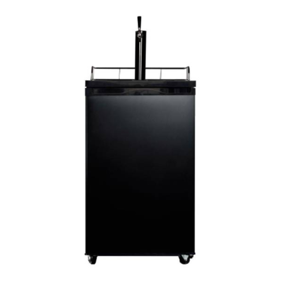
(The picture is only for reference, and specific appearance and configuration are subject to the real product)
Service Manual
Applicable Models
UR-PC160E-DQ
UR-PC160E-DQ
Prepared by
Reviewed by
Approved by
Service Manual, 2016-12
Model Code
22033210000002
22033210000062
R&D:Chen Feixiang
QA:Wang Tao
SVC:Chen Lei
R&D:Zhang Huawei
SVC:Guang Taoshuai
1 / 39
Advertisement
Table of Contents

Related Manuals for Midea UR-PC160E-DQ


Summary of Contents for Midea UR-PC160E-DQ
- Page 1 Service Manual, 2016-12 Service Manual Applicable Models Model Code UR-PC160E-DQ 22033210000002 UR-PC160E-DQ 22033210000062 (The picture is only for reference, and specific appearance and configuration are subject to the real product) Prepared by R&D:Chen Feixiang QA:Wang Tao Reviewed by SVC:Chen Lei R&D:Zhang Huawei...
- Page 2 Manufacturers or distributors are not responsible for the content of the Manual and interpretation thereof. Midea Refrigerators Technical Maintenance Manual Copyright @2016 All rights reserved. Replication of all or part of the Manual in any forms shall not be allowed without written approval by the Overseas Sales Corporation of Midea Refrigerators. 2 / 39...
-
Page 3: Table Of Contents
Service Manual, 2016-12 Contents 1.Safety Warning Code ..........................5 1.1Warning for operation safety ......................5 1.2Safety instruction for refrigerant ..................... 8 2.Description for product features ........................ 9 3.Installation and commissioning ....................... 10 3.1Handling ............................10 3.2 Door Disassembly and Assembly(None)..................10 3.3 Installation location ........................ - Page 4 Service Manual, 2016-12 9.3Alarm(None) ..........................24 9.4Failure code and solutions ......................24 9.5Defrost function ..........................25 9.6Compressor fan control (None) ..................... 25 9.7Self-diagnosis (None) ........................25 10.Circuit description ..........................26 10.1 Power Supply ..........................26 10.2Door trip test circuit(None) ......................27 10.3Temperature test circuit .......................
-
Page 5: Safety Warning Code
Service Manual, 2016-12 1.Safety Warning Code 1.1Warning for operation safety 5 / 39... - Page 6 Service Manual, 2016-12 6 / 39...
- Page 7 Service Manual, 2016-12 7 / 39...
-
Page 8: Safety Instruction For Refrigerant
Service Manual, 2016-12 1.2Safety instruction for refrigerant 8 / 39... -
Page 9: Description For Product Features
Service Manual, 2016-12 2.Description for product features This product is provided with following features: (The picture is only for reference, and specific appearance and configuration are subject to the real product) 1) Integrative refrigeration chamber 2) Electronic control 3) Polisher black tower with stainless steel trim 4)... -
Page 10: Installation And Commissioning
Service Manual, 2016-12 3.Installation and commissioning 3.1Handling 1) Protect the refrigerator in moving it Same as shown as left photo, please move it by handcart with cushion 2) Remove all packing materials and bottom cushion, then move into house for placement 3) After moving it to appropriate location, wait for 2 hours before power on. -
Page 11: Leveling Of The Refrigerator
Service Manual, 2016-12 3.4Leveling of the refrigerator If the refrigerator cannot be placed steadily, adjust the footing to level it. 3.5Door reversal(None) 3.6Installation of handle(None) 3.7 Installation of door lock(None) 3.8 Adjustment to level the door(None) 4.Terms 4.1 Definition of model(None) 4.2Location of nameplate (The picture is only for reference, and specific appearance and configuration are subject to the real product) -
Page 12: Product Specification
Service Manual, 2016-12 5.Product specification 5.1 Type specification(None) 5.2 Electrical parameters Product Name UR-PC160E-DQ UR-PC160E-DQ 22033210000062 Product Code 22033210000002 Name Item Type Specification Specification Specification EZ59E1C HDL100D Compressor MSC31F39K3* Starter QP2-4R7 ZHB73-120P4.7* Overload MSC31F39K3* DRB17N61A1 protector ZHB73-120P4.7* Compressor Winding 8.8±7%Ω... -
Page 13: Inside Temperature
Service Manual, 2016-12 5.3Inside temperature Temperature tolerance ≤ 2°C Compartment The highest (° C) Lowest (° C) Refrigerating 5.4Defrosting parts(None) 5.5Circuit diagram 13 / 39... -
Page 14: Internal View And Dimension
Service Manual, 2016-12 6.Internal view and dimension 6.1Main parts and their names (The picture is only for reference, and specific appearance and configuration are subject to the real product) 1.Beer tower 4.Shelf 2.Guardrail 5.Beer can bottom pad 3.Fan 6.2External dimension Front view Side view 14 / 39... - Page 15 Service Manual, 2016-12 Down view Open Door Maximum open angle of door(180° ) (The picture is only for reference, and specific appearance and configuration are subject to the real product) 15 / 39...
-
Page 16: Refrigerating Piping System And Circulating Route Of Cooling Air
Service Manual, 2016-12 7.Refrigerating piping system and circulating route of cooling air 7.1 Refrigerating piping system →3condenser→ 4Dry filter →5Capillary tube→ 6Evaporator→7 Exhaust transition pipe Return 1Compressor→2 →1Compressor transition pipe (The picture is only for reference, and specific appearance and configuration are subject to the real product) 7.2Circulating route of cooling air 16 / 39... -
Page 17: Dismantling Of Parts
Service Manual, 2016-12 8.Dismantling of parts 8.1 Parts on the door Door seal Door seal is installed into door liner groove. 1) Open the wine cabinet door; 2) Take the door seal ①out of door liner. 8.2Parts inside the wine cabinet Shelf 1)... -
Page 18: Light System(None)
Service Manual, 2016-12 8.3Light system(None) and fan motor Air duct components refrigeratingchamber Air duct components refrigeratingchamber None Fan motor of air duct Use a screwdriver to take down the screws on fan.Remove the connecting harness terminals linking the fan and cabinet and take down the fan.Remove the connecting harness terminals linking the fan and cabinet and take down the fan.Remove the... -
Page 19: Compressor Case
Service Manual, 2016-12 1) Take down screws and gaskets on the evaporator. 2) Remove the welding on inlet and outlet tubes. Components on the evaporator Defrost sensor Not replace The defrost sensor is located on back of the evaporator. Sensor Sensor in freezing chamber None Sensor in refrigerating chamber... - Page 20 Service Manual, 2016-12 Rear cover and compressor case 1)Remove by cross screwdriver the screws fixing back cover plate of compressor chamber anticlockwise 2)Take the back cover plate of compressor chamber upward. Terminal box of the compressor 1) Remove the screwsTwo screws outsideOne screw inside Remove the clipping stripSlowly pull it out 1.
- Page 21 Service Manual, 2016-12 Main control board box CapacitorCompressor coverCompressordrain Condenser-1(in)DrierCapillary trayCondenser-2(out) TubeTransition pipe Suction conection Pipe Condenser fan motor F an motor None Standby condenser None 8.8Temperaturecontrol panel 1. Remove the two screws linking the temperature control board mounting box to the 21 / 39...
- Page 22 Service Manual, 2016-12 2Disconnect the connector 3.Remove the temperature control panel 8.9main panel 1. Take down screws 2Take out main control panel cover 22 / 39...
-
Page 23: Bar Counter(None)
Service Manual, 2016-12 3. Disconnect the fast connector Bar counter(None) Disassembly and installation of bar counter None Disassembly and installation bar doorseal None Water dispenser(None) 8.10 Disassembly and installation of water valve None Disassembly and installation of water tank None Ice maker(None) 8.11 Disassembly and installation of ice maker... -
Page 24: Function And Operation
Service Manual, 2016-12 9. Function and operation 9.1operation panel Powering on each time, the display screen gives a full display for 3s; then the panel displays normal. Normal displayDisplay area lighten all the time: If the system has an error, the area display relevant error code (circularly). -
Page 25: Defrost Function
Service Manual, 2016-12 Step 1: Check whether the terminal CN3 and CN5 is well stuck, pull out the terminal and re-stick it in place Step 2: Check to see if there’re foreign matters on the terminal. Fault of frost sensor Step 3: Inspect the defrost sensor whether contact is bad, and resend contact the fast connector Step 4: Replace main control board... -
Page 26: Circuit Description
Service Manual, 2016-12 10.Circuit description 10.1 Power Supply AC input voltage is lowered by linear transformer, then filtered by rectifier diode & LC into DC 12V, DV12V provide power to reply what controls the switches of compressor and defroster. DC12V is changed through adjuster 7805 in to stable DC5V,DC5V provide the power to control chip, control chip monitor the temperature changes in the refrigeratorIf no power detected in test, firstly check whether there is input voltage between the L&... -
Page 27: Door Trip Test Circuit(None)
Service Manual, 2016-12 10.2Door trip test circuit(None) 10.3Temperature test circuit The characteristic that resistance value reduces as the temperature increases is deemed to have negative slope or negative temperature coefficient (NTC), and such thermostat is called as NTC thermostat. The resistance value changes sensitively with temperature and typically changes 7% ~ 3% per degree centigrade. -
Page 28: Fan Motor Circuit Of The Freezing Chamber(None)
Service Manual, 2016-12 10.4Fan motor circuit of the freezing chamber(None) 10.5Refrigerator fan motor circuit The fan motor of refrigerator runs with the compressor, at this moment check if there is 12V voltage between FAN pin and GND, in normal running, FAN is high-level input, there is 6V more voltage between FAN pins. -
Page 29: Condensing Fan Motor Circuit (None)
Service Manual, 2016-12 10.6Condensing fan motor circuit (None) 10.7Damper motor circuit (None) 10.8(R/T)Resistance value of the sensor (R/T) Tx(℃) R(KΩ) Tx(℃) R(KΩ) Tx(℃) R(KΩ) Tx(℃) R(KΩ) Tx(℃) R(KΩ) 33.81 14.31 6.495 3.141 1.617 31.85 13.55 6.175 2.999 1.55 30.01 12.83 5.873 2.865 1.486... -
Page 30: Trouble Shooting Method
Service Manual, 2016-12 11.Trouble shooting Method 11.1No cooling 30 / 39... -
Page 31: No Working Of Compressor
Service Manual, 2016-12 11.2No working of compressor 31 / 39... -
Page 32: Inside Frosting, No Defrosting
Service Manual, 2016-12 11.3Inside frosting, no defrosting 32 / 39... - Page 33 Service Manual, 2016-12 33 / 39...
-
Page 34: Lights Inside The Refrigerator Don't Light Up(None
Service Manual, 2016-12 11.5Lights inside the refrigerator don’t light up(None) 11.6Air duct not operated(None) 11.7Fan failure(None) 11.8Defective defrost circuit(None) 11.9Noise 34 / 39... -
Page 35: Figures And Details Of Repair Parts(Documents Are Provided Separately)
Service Manual, 2016-12 12. Figures and details of repair parts( Documents are provided separately 12.1Figures 12.2List of parts and components 13Appendix: 13.1Electrical Schematic Diagram(None) 13.2Refrigerator maintenance tooling and equipment and material Tooling Name Photo Main Usage Phillips screwdriver screw assemble and disassemble screw and rivet assemble and slotted screwdriver/scraper disassemble... - Page 36 Service Manual, 2016-12 handle assemble and Allen wrench(2.8~4mm) disassemble Vise grip pliers sealing process tube Pipe cutter pipe cutting Knife assistive tool Nipper pliers assistive tool Capillary tube scissors Shear capillary Equipment Name Photo Main Usage 36 / 39...
- Page 37 Service Manual, 2016-12 Vacuum pump vacuum pumping Electronic scale weighing refrigerant/gas pipe and cooling High pressure nitrogen with system(condenser, evaporator, piezometer etc) impurities clean Soldering gun heating and welding connection process pipeline, Quick coupling vacuum or charge refrigerant wi ll be used. welding point leakage detect, if hand leak detector no, use soap-suds...
- Page 38 Service Manual, 2016-12 Process pipeline Charge the refrigerant Involving a system failure to be Dry filter replaced Copper welding rod tube welding Refrigerant/gas Add refrigerant to the system door fixing for reversible door Sealing tape option 38 / 39...
- Page 39 Service Manual, 2016-12 Midea Refrigerators If you need to get detailed technical information from the manufacturer, please contact: xxx@midea.com Refrigeration Division Overseas Sales Company Address: No. 176, Jinxiu Avenue, Economic-Technological Development Area, Hefei, Anhui, China 39 / 39...
Need help?
Do you have a question about the UR-PC160E-DQ and is the answer not in the manual?
Questions and answers