Table of Contents
Advertisement
Quick Links
tekmarNet
2 House Control 402
®
Introduction
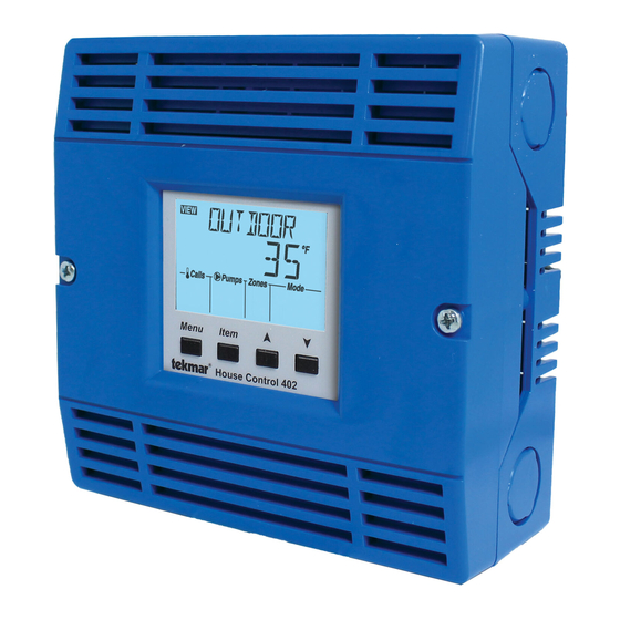
The House Control 402 is designed to operate as part of a
complete hydronic heating system with tekmarNet
thermostats. It can provide operation of two outdoor reset
water temperatures such as radiant floor heating on the first
temperature and baseboard or fan coil heating on the second
temperature. In addition the control has Domestic Hot Water
and Setpoint capabilities. It is easy to add more zones, add
schedules or other convenient accessories through the use
of the tekmarNet
4 (tN4) Expansion terminals.
®
VIEW
Calls
Boil Exp Boil System
Menu
Installation & Operation Manual
Pumps
Zones
1 2 3 4
Item
House Control 402
2 (tN2)
®
Features
• Single on-off, two-stage or modulating boiler
• Boiler outdoor reset temperature
• Mixing outdoor reset temperature
• Domestic Hot Water tank operation
• Setpoint operation
• Mix with variable speed injection, floating action,
or proportional 0-10 V (dc), proportional 4-20 mA
• For use with tekmarNet
• Four 24 V (ac) powered zone valve outputs
• Expand to 24 zones per temperature using
tekmarNet
• CSA C US Certified for use in USA and Canada
Benefits
• Energy efficiency through Outdoor Temperature
Reset with Indoor Feedback
• Indoor Feedback minimizes the water temperature
(increasing energy savings), and the efficiency of
your mechanical equipment through integrated
tekmarNet
• Zone Synchronization reduces equipment cycling
• Auto Differential - Reduces boiler cycling
• Compact enclosure for flexible installation
• Simple zone expansion using Wiring Centers
1 of 32
HVAC Systems Replaces: 09/10
2 Thermostats
®
4 expansion ports
®
Thermostats
®
© 2016
D 402
05/16
402_D - 05/16
Advertisement
Table of Contents

Related Manuals for Tekmar tekmarNet 2 House Control 402


Summary of Contents for Tekmar tekmarNet 2 House Control 402
- Page 1 Installation & Operation Manual D 402 tekmarNet 2 House Control 402 05/16 ® HVAC Systems Replaces: 09/10 Introduction The House Control 402 is designed to operate as part of a complete hydronic heating system with tekmarNet 2 (tN2) ® thermostats. It can provide operation of two outdoor reset water temperatures such as radiant floor heating on the first temperature and baseboard or fan coil heating on the second Features...
-
Page 2: Table Of Contents
It is your responsibility to ensure that this control is safely installed according to all applicable codes and standards. tekmar is not responsible for damages resulting from improper installation and/or maintenance. To avoid serious personal injury and damage to the equipment: •... -
Page 3: Physical Dimensions
• (2) #10 x 1" Wood Screws • 14 AWG Solid Wire (Line Voltage Connections) • (3) Wire Nuts • tekmar 009K (24 V (ac) transformer with 4" x 4" junction box) • 18 AWG LVT Solid Wire (Low Voltage Connections) • Cable or Conduit Connectors... -
Page 4: Sizing The Transformer
• If using a Floating Action mixing valve, add the VA Transformer 009 (or 009K which includes a 4”x 4” electrical draw for the actuating motor. A tekmar Actuating Motor box) can supply up to 40 VA, and includes an in-line fuse 741 draws 1.5 VA during normal operation. - Page 5 Figure 1 - Connect Figure 2 - Connect Ground Wires Neutral Wires Variable Speed Pump Variable Speed Pump Pump Pump Open Close Pump Pump DHW Pump DHW Pump Pump Pump Made in Canada tN2 tN2 tN2 tN2 tN2 tN2 tN2 tN2 Boil System Pump Boil System Pump Floating Action...
- Page 6 Applications that use a floating action mixing valve actuator • Connect the tN4 and C Boil Exp. terminals on the 402 (tekmar type 741) will use the Floating Action Opn, Cls, and to the corresponding tN4 and C Expansion terminals C terminals.
-
Page 7: Sensor Wiring
Front Low Voltage Wiring Diagram -------- -- -- - - -- - - - -- - - -- - - - -- - - - -- - - -- - - - -- - - - -- - - -- - - - -- - - - -- - - -- tekmarNet 2 Thermostats ®... - Page 8 (EMI), shielded cable or twisted pair should on tekmar be used or the wires can be run in a grounded metal control conduit. If using shielded cable, the shield wire should be connected to the Com or Com Sen terminal on the control and not to earth ground.
-
Page 9: Testing The Sensor Wiring
If the control display does not turn on, check the Input If a fault is suspected, contact your tekmar sales Power wiring terminals using an electrical multimeter. representative for assistance. -
Page 10: Max Heat
Step 8 The DHW pump turns on for 10 seconds. Testing the DHW Pump - - - - -- - - - -- - - --- - - - -- - - - Activate the User Test sequence and pause at Step 8 by Step 9 The boiler system pump turns on for 10 pressing the Item button once the DHW pump turns on. -
Page 11: Applications
Applications Single Boiler, DHW Tank, Variable Speed Mixing, 4 Mix Zones A402-1 Description: The House Control 402 operates an On/Off boiler with indirect Domestic Hot Water. Mixing is performed with variable speed injection, which supplies an outdoor reset water temperature to the 4 onboard mix temperature hydronic zones. - Page 12 Single Boiler, 2 Boiler Zones, DHW, 3 Way Mix, 4 Mix Zones A402-2 Description: The House Control 402 operates a modulating boiler with indirect Domestic Hot Water. Mixing is performed with a three-way floating action mixing valve, which supplies a reset water temperature to four mix temperature hydronic zones. Two boiler water temperature zones shown are operated by a Wiring Center through the tN4 Boil Expansion terminals.
-
Page 13: User Interface
User Interface Display Item Field Menu Field Displays the name Displays the of the selected item current menu VIEW ADJUST MONITOR Number Field Status Fields Displays the Displays the current current value of status of the control’s Calls Pumps WWSD Saving the selected item inputs, outputs and operation. -
Page 14: Navigating The Display
Navigating The Display The 402 uses a simple user interface to accomplish a are used to change the menu, sort through Items, and variety of functions. The four buttons beneath the display adjust each setting as required. Menu Button - -- - - --- ----------------------- - -- -- -- - - -- - - -- - - - -- - - - -- - - - -- - - -- - - - -- - - - -- - - -- - - - -- - - - -- The menus display in the Menu Field at the top left side of •... -
Page 15: View Menu
View Menu (1 of 1) The View menu items display the current operating temperatures and status information of the system. Item Field Range Description VIEW OUTDOOR SECTION B, C -76 to 149°F Current outdoor air temperature as measured by the outdoor sensor. The outdoor air temperature is shared to all thermostats in the tekmarNet (-60.0 to 65.0°C) ®... -
Page 16: Adjust Menu
ADJUST operate from fully closed to fully open. 30 to 230 seconds Installer tekmar actuating motors = 105 sec. Default = 105 seconds Refer to actuating motor for correct setting. Note: This item is only available when the Mix Type is set to FLOT (floating action motor), 0-10, or 4-20. - Page 17 Adjust Menu (2 of 3) Item Field Range Access Description Set to BOILER DESIGN SECTION C The supply water temperature required for the boiler zones to heat the building on the typical coldest day VIEW 70 to 200°F of the year. Recommendations: (21.0 to 93.5°C) High mass radiant floor = 120°F (50°C) Installer...
- Page 18 Adjust Menu (3 of 3) Item Field Range Access Description Set to 40 to 100°F ADJUST WWSD OCCUPIED SECTION I (4.5 to 38.0°C) Installer The system’s Warm Weather Shut Down temperature Default = 70°F User during Occupied periods or when a schedule is not used.
-
Page 19: Monitor Menu
Monitor Menu (1 of 1) The Monitor menu items provide information about the system’s operation and performance. To clear any item back to default, press and hold the Up and Down buttons while viewing that item. Item Field Range Description OUTDOOR HIGH MONITOR -76 to 149°F... -
Page 20: Toolbox Menu
Toolbox Menu (1 of 1) The Toolbox Menu is a location for system information and Test functions. If any errors are present on the system, they will be located at the beginning of this menu. Item Field Range Description USER TEST TESTING On or Off Begins the test routine which tests the main control’s functions. -
Page 21: Sequence Of Operation
Sequence of Operation tekmarNet System Section A ® tekmarNet is a family of products that use communication • Wiring Centers 313, 314, 315, 316 - Add additional zones ® to operate the HVAC system in a comfortable and efficient • tN2 and tN4 Thermostats - Add thermostats manner. -
Page 22: Boiler Temperature Reset Operation
Mixing Device Type -- ----------------------- -- - -- -- - -- - - - -- - - - -- - - - -- - - -- - - - -- - - - -- - - -- - - - --- - - -- - - - -- The House Control can operate a mixing device such as Modulating 0-10 V (dc) a mixing valve or variable speed injection pump based... -
Page 23: Domestic Hot Water Tank Operation
Domestic Hot Water Tank Operation Section D DHW Call -- -- -- --- ------------------------ -- -- - -- -- - -- - - - -- - - - -- - - - -- - - -- - - - -- - - - -- - - -- - - -- -- - - -- - - - -- A DHW Call is required in order for the control to provide heat to a DHW tank. - Page 24 DHW MODE 3 - DHW in Primary / Secondary no DHW Mode = 3 Priority When a DHW Call is present, the DHW pump and the boiler system pump is operated. Boiler temperature zones can turn on if required. Zone Valve DHW MODE 4 - DHW in Primary / Secondary with ON Or...
-
Page 25: Setpoint Operation
Setpoint Operation Section E A Setpoint Call is required in order for the control to provide When the control receives a Setpoint Call: heat to a setpoint load, such as a spa, pool, or snowmelt • All Boil zones are turned off. load. - Page 26 Staging controls that accept an EMS input. by the boiler manufacturer. It is the amount of time that • To use the tekmar EMS signal operation, the Boil Type the burner must operate before the internal boiler control setting in the Adjust menu must be set to EMS1.
-
Page 27: Domestic Hot Water Heat Source
In order to decrease temperature swings and increase boiler Auto Differential -- ----------------------- - -- -- -- efficiency, the Auto Differential feature automatically adjusts Both on-off and modulating boilers are operated with the operating differential of the boiler based on the heating a differential. -
Page 28: Energy Saving Features
Energy Saving Features Section I The “$aving” icon is displayed when energy is being saved. Further Savings! The following features reduce energy consumption. Use a Timer 033 with programmable schedule #1 to gain the WWSD Unoccupied setting. This provides an Network Schedules ------------------------ -- -- additional WWSD temperature that can be set even lower... -
Page 29: Error Messages
Error Messages (2 of 3) Error Message Description OUTDOOR SENSOR OPEN CIRCUIT Due to an open circuit (disconnected or broken wire), the control failed to read the outdoor sensor. As a result, the control assumes an outdoor temperature of 32°F (0.0°C) and continues operation. -
Page 30: Frequently Asked Questions
Error Messages (3 of 3) Error Message Description MIX DEVICE LOST (1:01 TO 1:24) Each tekmarNet device (thermostat, setpoint control, timer) has an address. The device with ® this address on the mix water temperature is no longer reporting back to the 402. The device can be located by either the address, or by going to each device in the building, checking that the LCD is on, and the tekmarNet communication symbol is on. -
Page 31: Job Record
Frequently Asked Questions (2 of 2) Symptom Look For... Corrective Action Burner symbol on If the burner symbol is on the LCD, there is a problem with the boiler. Ensure the boiler aquastat manual limit is reset to the on position. Warm Weather Shut Down (WWSD) is an energy saving feature that prevents WWSD symbol on central heating during the summer. -
Page 32: Technical Data
& other contact informa- tion regarding the appropriate Representative. tekmar Control Systems Ltd., A Watts Water Technologies Company. Head Office: 5100 Silver Star Road, Vernon, B.C. Canada V1B 3K4, 250-545-7749, Fax. 250-984-0815 Web Site: tekmarControls.com 32 of 32 Product design, software &...
Need help?
Do you have a question about the tekmarNet 2 House Control 402 and is the answer not in the manual?
Questions and answers