Advertisement
Quick Links
- Data Brochure
Eight Stage Boiler Control 258
Setpoint
Power
WWSD
TEMP
ROOM
OUTSIDE
Actual
TIME
Heat
F C
Minimum
Supply
Demand
PRGM
1
Target
2
AMPM
Supply
UNOCC
USE
OVR
Pump
Comb. air
S
M T W T F S
Stage 1
Stage 2
Stage 3
Stage 4
Stage 5
Stage 6
Stage 7
Stage 8
Menu
Item
Override
Eight Stage Boiler Control 258
Heating
is required
LEDs and
LCD screen;
display of times
& temperatures
System Pump
is on
Programming
buttons
Stages 1 to 8
are on
Terminal Plugs:
Power and out-
put connections
24Vac power supply
Output: Turn
on System
Pump
Input: Heat Demand
signal. Optional
M
Output: Open
Combustion Air
Damper
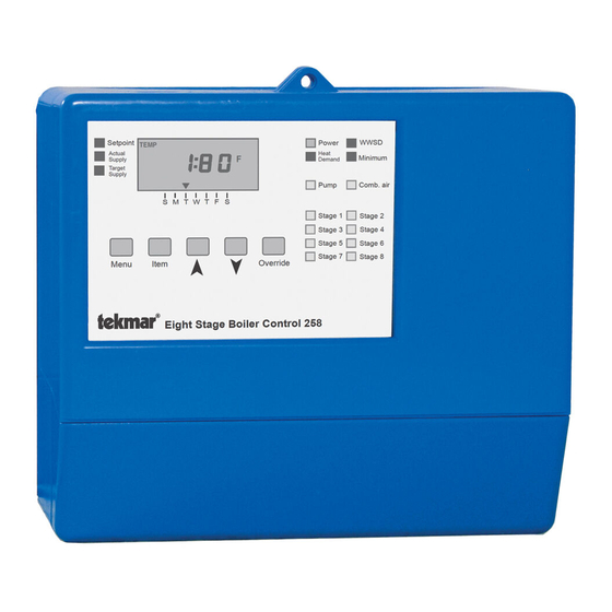
The tekmar Eight Stage Boiler Control 258 is a microprocessor-based control which
regulates the supply water temperature from up to 8 boilers based on the outdoor air
temperature, and optionally, the indoor air temperature through a tekmar 10K Zone
Control. The System pump is turned on when there is a Heat Demand and the outdoor
temperature is cool enough to require heat in the system. When a combustion air
damper is used, it must be opened before the first boiler is fired. The control has a
built-in setback timer and LCD screen to display temperatures and boiler running times.
Outdoor Reset Strategy . . . . . . pg. 2
Sequence of Operation . . . . . . pg. 4
Installation . . . . . . . . . . . . . . . . . pg. 7
Settings . . . . . . . . . . . . . . . . . . . pg. 10
Testing . . . . . . . . . . . . . . . . . . . . pg. 13
System is in
Warm Weather
24Vac power
Shut Down
supply is on
Setpoint
TEMP
ROOM
OUTSIDE
Actual
TIME
F C
Supply
PRGM
1
Target
2
AMPM
Supply
UNOCC
USE
OVR
S
M T W T F S
Menu
Item
Eight Stage Boiler Control 258
Maximum 24 volts
1
2
3
4
5
6
7
8
9 10
Power
System
Heat
Comb.
Stage
C
R
Pmp
Pmp
Dem
Dem
Air
1
1
Output: Turn on stages #1 to #8
Control is
maintaining
Minimum Supply
Power
WWSD
Heat
Minimum
Demand
Pump
Comb. Air
Stage 1
Stage 2
Stage 4
Stage 3
Stage 5
Stage 6
Stage 7
Stage 8
Override
Date
11 12
13 14
15 16
17 18 19 20 21 22 23
Stage
Stage
Stage
Stage
Stage
Stage
2
2
3
3
4
4
5
5
6
6
7
Error Messages . . . . . . . . . pg. 14
Programming . . . . . . . . . . . pg. 15
Pre-Programed Schedules pg. 18
Technical Data . . . . . . . . . . pg. 19
Limited Warranty . . . . . . . . pg. 20
Combustion air
Operating Mode
damper is open
selector switches
Fixed lead
Lo-Hi fire
Stage
Rotate
Fixed last
1 2 3 4 5 6 7 8
Int. timer
Auto
Stpnt
Perm.
Demand
External
1
2
3
4
5
6
7
8
9
1
2
3
4
5
6
Demand
Off
Reset
Off
Ext. timer
2.0
120°F
80
0.4
3.6
Off
170
Heating Curve
Minimum
22°F
2
42
T est
Boiler
Differential
Power Supply: 24V 60Hz 5VA
221092
Relay capacities: 24V 10A
S/N
1234567
No power here
24 25
26 27
28
29 30
UnO
10K
Com
Sup Out
N/C
Com
N/O
Sw
Zone
Sen
Sen
Sen
7
8
8
8
D 258
07/93
Heating Curve
setting
Minimum
Supply setting
Boiler
Differential
setting
Test button &
LED to test
main control
functions
Terminal Plug:
Sensor and
timer inputs
Input: Outdoor
Sensor 070
Included
Input: Supply
Sensor 071. Included
tekmar
Zone
Control
Input:
tekmar 10K
Zone Control
Optional
Input:
Unoccupied
signal.
Optional
Advertisement

Subscribe to Our Youtube Channel
Related Manuals for Tekmar Eight Stage Boiler Control 258


Summary of Contents for Tekmar Eight Stage Boiler Control 258
- Page 1 Eight Stage Boiler Control 258 07/93 The tekmar Eight Stage Boiler Control 258 is a microprocessor-based control which regulates the supply water temperature from up to 8 boilers based on the outdoor air temperature, and optionally, the indoor air temperature through a tekmar 10K Zone...
- Page 2 Very warm zone temperatures can shift the curve far enough down to put the control into WWSD at cool outdoor temperatures. Refer to the tekmar Essays E 001 and E 002 for more detailed information regarding control strategy and integration of control functions.
- Page 3 Notes on the operation of a PID control and the effect of the PID processing function on target temperature calculations and control response to temperature change. In order to reduce excessive temperature droop or overshoot control adjustments will have a temporary effect on the target temperature.
-
Page 4: Sequence Of Operation
Sequence of Operation When the Eight Stage Boiler Control 258 is powered-up, the "Power" light will come on and the full display along with all of the red temperature indicator lights are switched on for approximately 5 seconds. The Display will then default to show the "ACTUAL SUPPLY"... - Page 5 Reset Ext. timer tekmar 10K Zone Control function The control will monitor the indoor temperatures of all zones, as well as the outdoor and supply temperatures, and shift the Heating Curve (and the WWSD point) up or down to fine adjust the system supply water temperature for whichever zone requires the hottest supply water.
- Page 6 Outdoor temperature cold enough for heating curve operation The " Comb. air" light will come on and the control will wait for 60 seconds (to ensure that the combustion air damper has had enough time to open). One or more "Stage" lights will come on and the control will stage on the boilers based on its PID calculations. The boilers will fire until the supply temperature reaches the heating curve target temperature plus one half the Boiler Differential setting.
-
Page 7: Installation
Standard 18 to 22AWG solid wire is recommended for all low voltage wiring to tekmar controls. Heavier guage wire may not fit properly into the terminal plugs, while lighter guage wire is too fragile and may also contribute too much resistance to the circuit. - Page 8 Com Sen — Sup Sen (28 and 29). Zone Option: Indoor temperature feedback, tekmar 10K Zone Control Only Connect the two wires from a tekmar 10K Zone Control to terminals 10K Zone — Com Sen (27 and 28). Zone Option: Occupied/Unoccupied switch input, when not using Internal timer Connect the two wires from the Occupied/Unoccupied dry contact switch (timer, relay, etc.) to terminals UnO Sen —...
- Page 9 Caution its header on the control The tekmar Eight Stage Boiler Control 258 is an operating control and is not certified or intended for use as a safety device. Under no circumstances should safety limit devices be left disconnected after installation of this control.
- Page 10 For specific application details refer to Application Brochure A 258. A more detailed technical description of the effect of control settings on overall system operation is described in the tekmar Essay, E 002. Reset operation Stpnt —...
- Page 11 Common Settings Stage 1, 2, 3, 4, 5, 6, 7, & 8 Auto or Off switch Fixed lead Lo-Hi fire Stage Rotate Fixed last 1 2 3 4 5 6 7 8 Int. timer When a stage switch is set to "Auto", that particular stage becomes active and its Auto Stpnt Perm.
- Page 12 Heating temperatures to below boiler minimums, or some sort of room temperature control and zoning (88) Curve system. Zone controls from tekmar, when used in these applications, will provide room Minimum Supply (77) Setting 130°F temperature feedback information to this control, allowing it to shift the heating curve for maximum comfort and energy savings.
- Page 13 Operational test of control functions - Test button See page 3 The Eight Stage Boiler Control 258 has a Test button which can be used W T F to test the main control functions any time there is a "fixed display"...
- Page 14 ERROR MESSAGES Error Messages If a sensor fault occurs during normal Step Eight Troubleshooting operation or during the test routine, the word As in any troubleshooting procedure, it is important to isolate a "Err" will appear in the display screen and the problem as much as possible before proceeding.
- Page 15 MENU ACCESS – VIEWING TEMPERATURE MENU – VIEWING/PROGRAMMING Fixed displays will deliver continuous readout Fixed displays will deliver continuous readout unless manually changed by keypad command unless manually changed by keypad command Time-out displays will automatically revert to Fixed Time-out displays will automatically revert to Stable display #1 after 20 seconds of no keypad action display #1 after 20 seconds of no keypad action To prevent a display time-out while programming...
- Page 16 TIME/DAY MENU – PROGRAMMING PROGRAM MENU – VIEWING Fixed lead Lo-Hi fire Stage Note: These program displays are "Time-out" displays Rotate Fixed last 1 2 3 4 5 6 7 8 Int. timer Auto Stpnt Perm. 1 2 3 4 5 6 7 8 Int.
- Page 17 PROGRAM MENU – "P 0" PROGRAMMING OCCUPIED/UNOCCUPIED OVERRIDE Note: All "PROGRAM" displays are "Time-out" displays 1 2 3 4 5 6 7 8 Int. timer 1 2 3 4 5 6 7 8 Int. timer Auto Stpnt Perm. Auto Stpnt Must be set to Perm.
- Page 18 PRE-PROGRAMMED SCHEDULES Schedule "P 2" Schedule "P 3" Schedule "P 1" Time Temperature Time Temperature Time Temperature Sunday 9:00 am Occ 1 Sunday 8:00 am Occ 1 Sunday 8:00 am Occ 1 10:30 pm UnOcc 1 9:30 pm UnOcc 1 10:30 pm UnOcc 1 Null...
-
Page 19: Technical Data
Technical Data Technical Specifications Dimension (h x w x d) — 6-5/8" x 7-9/16" x 2-13/16" (170 x 193 x 72mm) Weight — 2.9 lbs (1.3 Kg) Ambient — 30 to 120°F (0 to 50°C), < 95% RH non-condensing — 24Vac ± 10%, 60Hz, 5VA class II Power supply —... -
Page 20: Limited Warranty And Product Return Procedure
12 months from the date of installation of the product, whichever occurs first. tekmar can take back the product for a return charge of 40% of the product's net value. This Replacements: tekmar can send replacement products if requested. All replacements are invoiced.
Need help?
Do you have a question about the Eight Stage Boiler Control 258 and is the answer not in the manual?
Questions and answers