Advertisement
- 1 Important safety information
- 2 CMS 50 and CMS 65 Packaging content
- 3 Preliminary recommendations
- 4 Overview
- 5 Installation
- 6 Audio input connections
- 7 Tweeter phase plug
- 8 Positioning
- 9 Running in
- 10 CMS 50 and CMS 65 controls
- 11 Fixing Accessories
- 12 Specifications
- 13 CMS SUB Packaging content
- 14 Audio connections: CMS SUB
- 15 CMS subwoofer controls
- 16 CMS SUB Specifications
- 17 Warranty
- 18 Documents / Resources
Important safety information
An example of this equipment has been tested and found to comply with the following European directives and international standards:
Electromagnetic compatibility
EN 55103
EN 61000
Electrical safety
EN 60065

Risk of electric shock
Do not open
Do not expose to rain or moisture
Please read carefully the following instructions and safety information. Heed all warnings and follow all instructions.
- Do not remove the back panel. There is no user serviceable parts inside; please refer to qualified service personnel.
This equipment must be earthed.
- Protect the power cord from being walked on or pinched particularly at plugs, convenien-ce receptacles, and the point where they exit from the apparatus.
- Only use attachments/accessories specified by the manufacturer.
- Servicing is required when the unit has been damaged in any way, such as damaged power cord or plug, spilled liquid or objects fallen into the unit, unit exposed to rain or moisture, when it does not operate normally or has been dropped.
- Do not place naked flame sources, such as lighted candles on the apparatus.
- Use the apparatus only in moderate climates (not in tropical climates).
- Do not expose the apparatus to dripping or splashing.
- Do not place objects filled with liquids, such as vases, on the apparatus.
CMS 50 and CMS 65 Packaging content
The loudspeaker is supplied with the following elements (apart from this manual):
- 1 power cord
- 4 rubber feet
- 2 adjustable spikes
- 1 rubber table stand
- 1 phase plug (tweeter)
- 1 protection grille for the tweeter with phase plug (we advise you to remove it before liste-ning to the speakers.)
- 1 protection grille for the woofer (we advise you to remove it before listening to the spea-kers.)
- 1 hook to remove the tweeter and woofer grilles
- 1 guarantee card
Please check that none of these items is missing, and remove all accessories from the box.
Preliminary recommendations
We would like to give a word of warning about the high sound pressure levels that can be generated by these loudspeakers, especially in a 5.1 configuration. Because of their low levels of distortion, and the minimal fatigue incurred by the user, it is not always obvious to realize the actual sound pressure level while working. Please bear in mind that exposure to excessive levels over a sustained period of time may lead to permanent hearing loss.
Overview

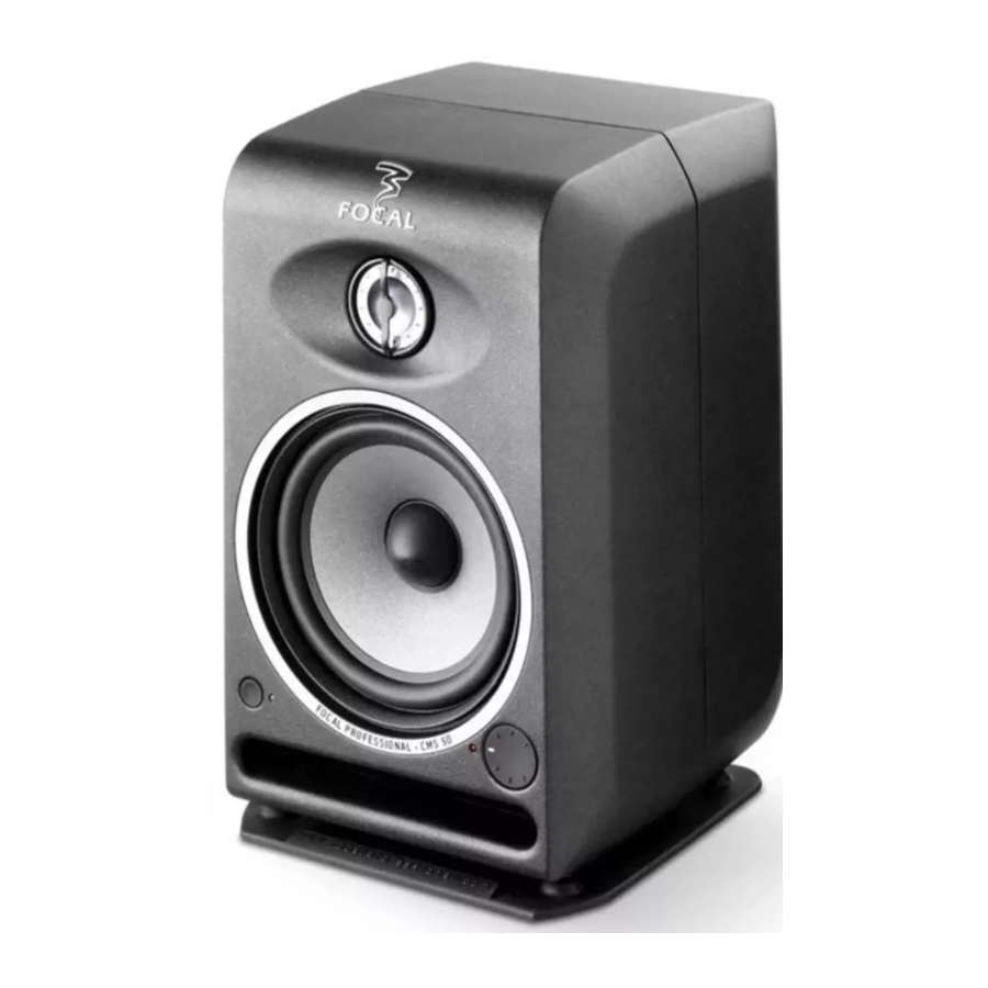
CMS 50
The CMS 50 is an active 2-way near field professional monitoring loudspeaker (2 internal amplifiers), composed of a 5" (13cm) Focal woofer/midrange speaker with a Polyglass cone loaded in a large laminar port and of a Focal inverted dome tweeter in aluminum/magnesium.

CMS 65
The CMS 65 is an active 2-way near field professional monitoring loudspeaker (2 internal amplifiers), composed of a 6.5" (16.5cm) Focal woofer/midrange speaker with a Polyglass cone loaded in a large laminar port and of a Focal inverted dome tweeter in aluminum/magnesium.
Installation
 Mains voltage
After having unpacked the unit, first check that the operating voltage is correctly set (see location on rear panel). If it is not, adjust the selector to the appropriate position. Also check and if necessary replace the fuse, which rating depends on the operating voltage (please refer to technical specifications).
Your products must be earthed using the power cord supplied.
Audio input connections
The audio signal input is to connect, up to your own choice, whether to the XLR inlet or RCA inlet.
The XLR inlet permits the connection of a source with symmetrical signal and uses standard wiring instructions:
Pin 1 = Ground (shield)
Pin 2 = In phase voltage ("hot")
Pin 3= Out-of-phase voltage ("cold").
The RCA inlet permits the connection of a source with asymmetrical signal. It's common to link the out-of-phase voltage (Pin 3) to the ground (Pin 1). This connection is generally made at wire level.
Tweeter phase plug
The CMS speakers are delivered with grilles for woofer and tweeter. In order to optimize the sound stage precision, we advise you to remove the grilles thanks to the hook included in the packaging. Then, install the phase plug on the tweeter in the vertical position by gently push on the suburbs of the phase plug (see below).

Positioning
The CMS loudspeakers are near field monitoring loudspeakers and should be positioned at a distance between 1 and 3 meters from the listener, pointing towards the listening position. They can be sitting on the console top, hung or even placed on appropriate stands. In any way, it is recommended that the tweeter is at a height from the floor approximately equivalent to that of the listener's ears. If required, it can make sense to place the speakers upside down so that the previous rule is better fulfilled.
The CMS loudspeakers could be placed vertically or horizontally depending on the environment, preferably pointing towards the listener.


Once the position is defined, you have 2 kinds of feet (4 rubber feet and 2 adjustable spikes) to optimize the loudspeaker positioning. The adjustment of the spike height permits to control the height of the soundstage. The gap and the right/left positioning of each loudspeaker permit to control the width, the centering and the global coherence of the soundstage (left/center/right), at the source of your recording precision.


Running in
As in all brand new loudspeaker, the drivers need some run-in period: the CMS transducers are mechanical elements demanding a little time to settle and adapt to the climatic environment. This period will vary, depending on the working conditions and may take up to a few weeks.
Avoid pushing the speakers very hard during their first hours of use, but to accelerate the run-in process, it is good practice to operate the speakers at moderate levels for 20 hours or so, with programs having significant low frequency content. Only once the transducers have come to stabilize will you get the optimum performance.
CMS 50 and CMS 65 controls

CMS 50

CMS 65
- HI-PASS FILTER
The HI-PASS FILTER rotative switch permits to activate or not the 12dB/octave high-pass filter. We advise you to set the rotative switch on FULL RANGE (deactivate the high-pass filter) in the case of a use in stereo configuration (2.0). We advise you to use the positions 45, 60 or 90Hz in the case of a use of the system with one or several subwoofers. - LF SHELVING
The LF SHELVING rotative switch permits to activate or not a correction of the sound level under 450Hz. We advise you to set the LF SHELVING rotative switch on +2dB when the premises acoustics naturally softens that frequency range. We advise you to set the LF SHELVING rotative switch on FLAT when the premises acoustics is neutral. We advise you to set the LF SHELVING rotative switch on –2, -4, or –6dB when the loudspeakers are placed next to a wall or an angle. - DESKTOP NOTCH
The DESKTOP NOTCH rotative switch permits to activate or not a correction of the sound level at a central frequency of 160Hz for a Q factor of 2. We advise you to set the rotative switch on –2, -4 or –6dB when the loudspeakers are positioned on a table, a console or any other support that creates reflections.

- HF SHELVING
The HF SHELVING rotative switch permits to activate or not a correction of the sound level from 4.5 kHz. We advise you to set it on:

- +2dB when the premises acoustics naturally softens this frequency range (mat environ-ment).
- FLAT when the premises acoustics is neutral.
- –2 or –4dB when the premises acoustics naturally increases this frequency range (brilliant environment)
- INPUT LEVEL
The INPUT LEVEL rotative switch function is to make the output sensitivity of the mixing console, or any other source, correspond to the input sensitivity of the loudspeakers. The available sensitivities are +4dBu, 0, -10dBv. The +4dBu position corresponds to the professional standard. The -10dBv corresponds to the general public standard. The 0 position is an intermediate position. - FIXING POINTS
The fixing points are made to ensure the link between the loudspeaker and a fixing support (stand, wall fixing, ceiling fixing, ...).The thread type is BSW 3/8". - BALANCED INPUT
The XLR inlet permits the connection of a source of symmetrical signal and follows standard wiring instructions.
Pin 1 = ground (shielding)
Pin 2 = In phase voltage (hot)
Pin 3 = Out-of-phase voltage (cold) - UNBALANCED INPUT
The RCA inlet permits the connection of a source of asymmetrical signal. It is common to link the out-of-phase voltage (Pin 3) to the ground (Pin 1). This connection is generally made on the wires. - ON/OFF Switch
The ON/OFF switch permits to put the internal amplifiers ON or OFF. - ON/STANDBY Switch
The ON/Standby switch permits to activate or to put the CMS loudspeaker in Mute. The LED is green when the loudspeaker is activated. The LED is red when the loudspeaker is in Standby. - VOLUME
The level rotative switch permits to adjust the level of the CMS loudspeaker. In position 0 (complete counterclockwise rotation), the loudspeaker is in Standby. In position 1(complete counterclockwise rotation + 1 notch), the softening is of –66dB. The last notch (complete clockwise rotation), corresponds to 0dB. - LED
The LED is red when the loudspeaker is in standby. The LED is green when the loudspeaker is activated. - CLIP INDICATOR
The clip indicator permits to control the audio signal quality. When the LED is lit up, the clip is activated. It means that the signal is saturated and does not permit to work in good conditions. You must avoid activating the clip. To do so, you must reduce the input signal level in the CMS loudspeaker and/or reduce the loudspeaker sound level 11.
Fixing Accessories
| Description | Brand | Reference | CMS 50 | CMS 65 |
| Stand (950-1430mm / 37-3/8" - 56-5/16") | K&M | 26740 | x | x |
| Table stand (micro stand 355-580mm / 14"- 22-13/16") | K&M | 23300 | x | x |
| Ceiling fixing (0-45°adjustable/360°rotating/260mm (10-1/4") height) | K&M | 24485 | x | |
| Wall fixing (rotating/distance from wall 105mm/ 4-1/8") | K&M | 24180 | x | x |
| Wall fixing (adjustable/rotating) | OMNIMOUNT | 20.5 WA | x | x |
| Ceiling fixing (adjustable/rotating) | OMNIMOUNT | 20.5 CA | x | x |
| Wall fixing (adjustable/rotating) | OMNIMOUNT | 20.5 ST | x | x |
| Wall fixing (adjustable/rotating/important distance from wall) | OMNIMOUNT | 20.5 STX | x | |
| Structure fixing (to be used with all the OMNIMOUNT Ballshaft fixations 20.5) | OMNIMOUNT | 20.5 C CLAMP | x | x |
Specifications
| System | CMS 50 | |
| 55Hz - 28kHz | |
| 105dB SPL (peak @ 1 m) | |
| Electronic section | ||
|
| Balanced 20 kOhms / Unbalanced 47 kOhms |
| XLR / RCA | |
| 80W rms, classe AB | |
| 50W rms, classe AB | |
|
| 220-230V (1.6A fuse rating) 120V (3.15A fuse rating) 100V (4A fuse rating) |
| IEC inlet and detachable power cord | |
|
| Ajustable, +4dBu / 0 / -10dBV |
| Ajustable, -66 dB / 0dB | |
| Ajustable, inactive / 45 / 60 / 90 Hz (12dB /oct.) | |
| Ajustable, 0 / -4 / -2 / +2dB | |
| Ajustable, 0 / -4 / -2 / +2dB | |
| Ajustable, 0 / -2 / -4 / -6dB | |
| Power ON / OFF switch, mains voltage selector | |
| Standby / ON switch | |
| Power ON/OFF LED | |
| Power ON/OFF LED | ||
| Audio clip LED | ||
| Transducers | ||
| 5" Focal drive unit, Polyglass cone | |
| Aluminium/Magnesium inverted dome Focal tweeter | |
| Integral by compensation magnet | |
| Cabinet | ||
| Reinforced and damped die cast aluminum cabinet | |
| Black powder coating | |
| 289.5x190x201mm (11.4"x7.5"x7.9") | |
| 299.2x190x201mm (11.8"x7.5"x7.9") | |
| 7,7kg (17 lb) | |
| System | CMS 65 | |
| 45Hz - 28kHz | |
| 108dB SPL (peak @ 1 m) | |
| Electronic section | ||
|
| Balanced 20 kOhms / Unbalanced 47 kOhms |
| XLR / RCA | |
| 100W rms, classe AB | |
| 60W rms, classe AB | |
|
| 220-230 V (1.6 A fuse rating) 120 V (3.15 A fuse rating) 100 V (4 A fuse rating) |
| IEC inlet and detachable power cord | |
|
| Ajustable, +4 dBu / 0 / -10dBV |
| Ajustable, -66 dB / 0dB | |
| Ajustable, inactive / 45 / 60 / 90 Hz (12dB / oct.) | |
| Ajustable, 0 / -4 / -2 / +2dB | |
| Ajustable, 0 / -4 / -2 / +2dB | |
| Ajustable, 0 / -2 / -4 / -6dB | |
| Power ON / OFF switch, mains voltage selector | |
| Standby / ON switch | |
| Power ON/OFF LED Power ON/OFF LED Audio clip LED | |
| Transducers | ||
| 6.5" Focal drive unit, Polyglass cone | |
| Aluminium/Magnesium inverted dome Focal tweeter | |
| Integral by compensation magnet | |
| Cabinet | ||
| Reinforced and damped die cast aluminum cabinet | |
| Black powder coating | |
| 358.5 x 241 x 231mm (14.1"x9.5"x9.1") | |
| 368.5 x 241 x 231mm (14.5"x9.5"x9.1") | |
| 10.5kg (23.1 lb) | |
CMS SUB Packaging content
To remove the loudspeaker from its box without damage, open the end flaps fully and bend them right back. Then remove the upper cushion and lift the loudspeaker out gently. Inspect the speaker for signs of any possible damage. In the unlikely event of this having occurred, please inform the carrier and supplier. It is a good practice to keep the packaging in case of future transportation.
The CMS SUB is supplied with the following elements (apart from this manual)
- 1 power cord
- 1 guarantee card
- 1 protection grille for the subwoofer (we advise you to remove it before listening to the CMS SUB).
The CMS SUB is an active subwoofer (1 internal amplifier) designed for Professional monitoring systems. It uses a 11" drive unit equipped with a "Polyglass" cone, and loaded by a large cross-section laminar port.

The CMS SUB may be used:
- for bass or sub-bass enhancement in stereo + sub setups (2.1 or 2.2). The rear panel of the CMS SUB allows for the connection of a traditional stereo source (Left In / Right In).
- as a LFE channel (Low Frequency Effects) in a multi-channel installation (5.1, 5.2, 6.1...), via a dedicated input of the rear panel.
Audio connections: CMS SUB

Stereo + Sub setup (2.1 or 2.2):
Left IN: this input is intented to receive the signal coming from the left channel of your source (mixing console, or other...).
Right IN: this input is intented to receive the signal coming from the right channel of your source (mixing console, or other...).
Left OUT: this output is intended to connect to the left main loudspeaker of your system. The signal supplied by this output is not internally processed. You have to engage the high pass filter on the CMS monitors to ensure perfect coupling and to avoid overlapping.
Right OUT: this output is intended to connect to the right main loudspeaker of your system. The signal supplied by this output is not internally processed. You have to engage the high pass filter on the CMS monitors to ensure perfect coupling and to avoid overlapping.
Multichannel configuration:
LFE: this input is intended to feed your CMS SUB in a multichannel application (5.1, 5.2, 6.1, ...): this channel is dedicated to low frequencies only.
Optimal positioning of the CMS SUB may vary depending on the surface, the shape and acoustic properties of the listening room.
You are advised to try various locations so to choose the one giving the best possible and most level sound balance. As a rule of thumb the optimal location will often be in a corner of the room.
CMS subwoofer controls
- LEVEL
This adjustement allows to set the sound level of the subwoofer relative to that of the main loudspeakers. It should also be optimised taking into account the actual location of the subwoofer and its acoustic consequences: for example in an angle the 6 dB acoustic gain should be compensated by an equivalent attenuation to maintain the overall balance of the system. - MUTE
This switch will turn out the output signal of the subwoofer channel (making it silent does not require to switch the power off). - LO PASS
This potentiometer adjusts the cut-off frequency of the low pass filter on the subwoofer channel, thus setting the upper frequency range to be reproduced by the CMS Sub. The goal is to achieve the smoothest frequency response of the whole system: sub + monitors. - POLARITY
This switch inverts the signal polarity on the subwoofer channel (ie 180° phase shift). - PHASE
This potentiomer provides some fine ajustment of the phase on the subwoofer channel. Combined with the polarity switch it can be used to compensate for the spacing between the sub and the main speakers, so to get a coherent soundfield through a proper time alignment of the different sources. - SUB BYPASS
This input allows for plugging in a control footswitch (not supplied) via a ¼" jack connector. Turning it active will mute the subwoofer channel. This facility allows for instantaneous comparison between the 2.1 configuration (with sub) and the traditional stereo setup (without sub) with the same system. - POWER INDICATOR
Power "LED" indicator
CMS SUB Specifications
| System | CMS SUB | |
| 30Hz - 250Hz | |
| 113dB SPL (peak @ 1 m) | |
| Electronic section | ||
|
| Left, Right, LFE |
| Electronically balanced / 10kOhms | |
| Female 3 pins XLR Variable | |
|
| Left, Right Male 3 pins XLR in parallel on inputs |
|
| |
|
| Left + Right mono summation LFE + lo-passed mono sum 24dB/octave variable lo-pass filter Phase adjustment Polarity |
| Sub level (sensitivity) adjustment Lo-pass frequency adjustment Phase adjustment Polarity switch Mute External Mute (controlled by external footswitch) | |
| Power on Mute External Mute | |
|
| 230V (T1.6AL fuse rating) or 115V (T3.15AL fuse rating) |
| IEC inlet and detachable power cord | |
| Transducers | ||
| Polyglass, high excursion Focal, 270mm (11") drive unit | |
| Cabinet | ||
| 22mm MDF panels with internal braces | |
| Dark grey vinyl | |
| 435,5mm x 366mm x 440mm (17.1" x 14.4"x 17.3") | |
| 23kg (50.7lb) | |
Warranty
These products are guaranteed against defects in components and workmanship only, for a period of 2 years. During the warranty period, Focal will, at their discretion, either repair or replace products which prove to be defective, provided that the product is returned, shipping prepaid, to an authorized Focal service facility.
Defects caused by unauthorized modifications, accident, negligence or any misuse are not covered by this warranty. For further information, please contact your dealer or the distributor in your country.
Focal® is a trademark of Focal-JMlab® - BP 374 - 108, rue de l'Avenir - 42353 La Talaudière cedex - France - Tel. (+33) 04 77 43 57 00 - Fax (+33) 04 77 43 57 04 - www.focal-fr.com

Documents / Resources
References
Download manual
Here you can download full pdf version of manual, it may contain additional safety instructions, warranty information, FCC rules, etc.
Advertisement


Need help?
Do you have a question about the CMS 50 and is the answer not in the manual?
Questions and answers