
Related Manuals for Mitsubishi MELSEC-F FX2N-32CAN

Summary of Contents for Mitsubishi MELSEC-F FX2N-32CAN
- Page 1 All manuals and user guides at all-guides.com HARDWARE MANUAL -32CAN Communication Module...
- Page 2 • If in doubt about the operation or use of the communication facilities of the FX -32CAN module please consult the nearest Mitsubishi Electric distributor. • This manual is subject to change without notice.
- Page 3 All manuals and user guides at all-guides.com FX2N-32CAN Communication Module -32CAN Communication Module Manual number : JY992D92901 Manual revision : B Hardware Manual Date : May 2003...
- Page 4 All manuals and user guides at all-guides.com FX2N-32CAN Communication Module Guidelines for the safety of the user and protection of the FX -32CAN Communication Module. This manual provides information for the use of the FX -32CAN Communication Module. The manual has been written to be used by trained and competent personnel. The definition of such a person or persons is as follows: a) Any engineer who is responsible for the planning, design and construction of automatic equipment using the product associated with this manual should be of a competent...
- Page 5 All manuals and user guides at all-guides.com FX2N-32CAN Communication Module Note’s on the symbols used in this manual At various times through out this manual certain symbols will be used to highlight points of information which are intended to ensure the users personal safety and protect the integrity of equipment.
- Page 6 All manuals and user guides at all-guides.com FX2N-32CAN Communication Module • Under no circumstances will Mitsubishi Electric be liable responsible for any consequential damage that may arise as a result of the installation or use of this equipment. • All examples and diagrams shown in this manual are intended only as an aid to understanding the text, not to guarantee operation.
-
Page 7: Table Of Contents
All manuals and user guides at all-guides.com FX2N-32CAN Communication Module Table of contents Guideline ..................... iii 1. Introduction....................1-1 1.1 Features of the FX -32CAN Module..............1-1 1.2 External Dimensions and Each Part Name ............1-2 1.3 System configuration ................... 1-4 1.4 Applicable PLC .................... - Page 8 All manuals and user guides at all-guides.com FX2N-32CAN Communication Module 4. Buffer Memory Structure ...............4-1 4.1 Basic Buffer Memory Structure, BFM #0 ~ BFM #31 .......... 4-1 4.2 Buffer Memory Functions ..................4-2 4.2.1 Data Transfer Locations, BFMs #0~#19 and #100~#199 ......... 4-2 4.2.2 The Data Exchange Mode, BFM #20 ................
- Page 9 All manuals and user guides at all-guides.com FX2N-32CAN Communication Module 6. Diagnostics....................6-1 6.1 LED Status ......................6-1 6.1.1 The Power LED ......................6-1 6.1.2 The FROM/TO LED....................6-1 6.1.3 The RUN LED ......................6-2 6.1.4 The Rx/Tx LED ......................6-2 6.1.5 The ERROR LED ......................
- Page 10 All manuals and user guides at all-guides.com FX2N-32CAN Communication Module viii...
-
Page 11: Introduction
All manuals and user guides at all-guides.com FX2N-32CAN Communication Module Introduction 1. Introduction The FX -32CAN Communication Module is an interface block which connects the FX 2N(C) to an existing CANopen network. The CANopen network is an internationally accepted network for industrial automation. -
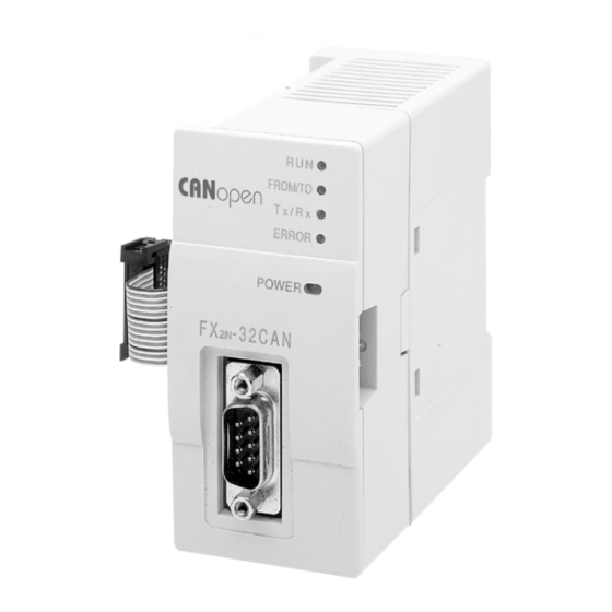
Page 12: External Dimensions And Each Part Name
All manuals and user guides at all-guides.com FX2N-32CAN Communication Module Introduction 1. External Dimensions and Each Part Name Dimensions: mm (inches) MASS (Weight): 0.2 kg (0.44 lbs) Accessory: Special block No. label R U N . R O M / T O T x / R x E R R O R P O W E R... - Page 13 All manuals and user guides at all-guides.com FX2N-32CAN Communication Module Introduction 1. a) Groove for DIN rail mounting (Width of DIN rail: 35 mm <1.38">) b) Hook for Din rail c) Extension cable d) Direct mounting holes (2-∅4.5 mm <0.18">) e) RUN LED: Lights when the FX -32CAN Communication Module is in Run mode.
-
Page 14: System Configuration
All manuals and user guides at all-guides.com FX2N-32CAN Communication Module Introduction 1. System configuration Network Configuration Manager CANopen Network Terminating Terminating Resistor 120Ω Resistor 120Ω Repeater CANopen CANopen Node 32CAN 32CAN Node The Maximum extension distance for the FX -32CAN module is 5000m at 10kbps (with repeaters). -
Page 15: Wiring
All manuals and user guides at all-guides.com FX2N-32CAN Communication Module Wiring 2. Wiring Caution for Wiring 1) Do not lay signal cable near high voltage power cables or put them in the same trunking duct. Otherwise, the effects of noise or surge induction are likely to take place. Keep a safe distance of more than 100 mm (3.94") from these wires. -
Page 16: Pin Configuration
All manuals and user guides at all-guides.com FX2N-32CAN Communication Module Wiring 2. Pin Configuration The module connector below is a 9-pin D-SUB (#4-40 inc. inch screw thread) type. Pin No. Signal Meaning Can_L Can_L bus line, dominant low Can_G Can_Ground Can_H Can_H bus line, dominant high 1,4,5,6,8,9 NC... -
Page 17: Specifications
All manuals and user guides at all-guides.com FX2N-32CAN Communication Module Specifications 3. Specifications Environmental/Standards Specifications Table 3.1: Environmental/Standards Specifications Item Description Environmental specifications excluding dielectric withstand Same as those of the main unit. voltage Dielectric Withstand Voltage 500 V AC > 1 min, tested between signal line and ground CAN Standard ISO 11898/1993 CANopen Standard by CiA... -
Page 18: Performance Specifications
All manuals and user guides at all-guides.com FX2N-32CAN Communication Module Specifications 3. Performance Specifications Table 3.3: Performance Specifications Item Description Maximum -32CAN The node address can be set from 1 ~ 127. A total of 30 nodes can be that can be Modules connected on each bus. -
Page 19: Buffer Memory Structure
All manuals and user guides at all-guides.com FX2N-32CAN Communication Module Buffer Memory Structure 4. Buffer Memory Structure Basic Buffer Memory Structure, BFM #0 ~ BFM #31 Table 4.1: Buffer Memory Structure, BFM #0 - BFM #31 BFM # READ (FROM) WRITE (TO) BFM #0 Received data (Section 4.2.1-2) -
Page 20: Buffer Memory Functions
All manuals and user guides at all-guides.com FX2N-32CAN Communication Module Buffer Memory Structure 4. Buffer Memory Functions 4.2.1 Data Transfer Locations, BFMs #0~#19 and #100~#199 These Buffer memory locations in the FX -32CAN module are used to receive from and transfer data to the CANbus. -
Page 21: Setting The Baud Rate, Bfm #24
All manuals and user guides at all-guides.com FX2N-32CAN Communication Module Buffer Memory Structure 4. 4.2.3 Setting the Baud Rate, BFM #24 BFM24 shows the current baud rate of the CANopen network, see the Table below. The baud rate can be set by writing TO BFM #24. The baud rate must be equal for all nodes on the CANopen network. -
Page 22: Reading The Communication Status, Bfm #25
All manuals and user guides at all-guides.com FX2N-32CAN Communication Module Buffer Memory Structure 4. 4.2.4 Reading the Communication Status, BFM #25 Read the CANopen module’s communication status from BFM #25 per the table below. Table 4.3: Communication Status b0: module online/offline module online module offline b1 ~ b7: reserved... -
Page 23: The Watch Dog Timer Setting, Bfm #26
All manuals and user guides at all-guides.com FX2N-32CAN Communication Module Buffer Memory Structure 4. 4.2.5 The Watch Dog Timer Setting, BFM #26 The Watch Dog Timer setting is stored in BFM #26 in units of 10 ms. A WDT error will occur if there is no FROM or TO instruction to any BFM for the time specified. -
Page 24: Error Staus, Bfm #29
All manuals and user guides at all-guides.com FX2N-32CAN Communication Module Buffer Memory Structure 4. 4.2.7 Error Staus, BFM #29 BFM #29 reflects the error status of the module. Bit 7 shows the status of the FROM/TO watchdog timer (see section 4.1.7, BFM #26). In case of a watchdog timer error (b7 is ON) an external emergency message will be sent to the CANopen network if the module is in operational mode. -
Page 25: Bfm Data Memory Backup
All manuals and user guides at all-guides.com FX2N-32CAN Communication Module Buffer Memory Structure 4. Table 4.5: Error Bit Description for BFM #29 b9: Command queue or event Data could not be written to internal N o c o m m a n d q u e u e o r eve n t queue overflow command queue or event queue queue overflow... -
Page 26: Extended Bfm Structure, Bfm #32 ~ Bfm #32767
All manuals and user guides at all-guides.com FX2N-32CAN Communication Module Buffer Memory Structure 4. Extended BFM Structure, BFM #32 ~ BFM #32767 Table 4.6: Extended BFM Structure BFM # READ (FROM) WRITE (TO) BFM #32 ~ #99 Reserved Reserved BFM #100 ~ #199 Received Output Data Transmit Data BFM #200 ~ #999... -
Page 27: Module Parameterization And Configuration
All manuals and user guides at all-guides.com FX2N-32CAN Communication Module Module Parameterization and Configuration 5. Module Parameterization and Configuration Each CANOpen node must have certain parameters defined in order to communicate information to other CANOpen nodes. These parameters include the Node Number, the baud rate, the Watch Dog Timer setting (specific for FX -32CAN module), and the communication mapping set. - Page 28 FX -32CAN node according to the pre-defined connection set of CANopen. Mapping Mode A - Mitsubishi Electric defined configuration for the FX -32CAN module that defines the relationship between up to eight FX -32CAN nodes, the node BFMs, and the Rx- PDOs and Tx-PDOs.
-
Page 29: Factory Default Mapping/Mode 0 Mapping
All manuals and user guides at all-guides.com FX2N-32CAN Communication Module Module Parameterization and Configuration 5. Factory Default Mapping/Mode 0 Mapping The Factory Default Mapping conforms to CANopen specification DS-301 and contains only the first 2 Tx-PDOs and the first two Rx-PDOs. Please refer to the two Tables in section 5.4 that give, repectively, the relationships between Tx-PDO number/COB-IDs/BFM# and the Rx-PDO/COB-IDs/BFM#. -
Page 30: Mode A Mapping
All manuals and user guides at all-guides.com FX2N-32CAN Communication Module Module Parameterization and Configuration 5. Mode A Mapping Setting up a CANopen network of only FX -32CAN nodes can be accomplished by simply using the Mode A Mapping configuration. Other types of CANopen modules can be added to the Network but additional user inputs are necessary. -
Page 31: Mode B Mapping
All manuals and user guides at all-guides.com FX2N-32CAN Communication Module Module Parameterization and Configuration 5. When all the stations have executed the Mode A Mapping command, it is possible to exchange 16 data words with every other FX -32CAN module*. Due to the data size, the number of nodes in this mapping Mode is limited to 8 stations. -
Page 32: Prepare The Pdo Mapping Table
All manuals and user guides at all-guides.com FX2N-32CAN Communication Module Module Parameterization and Configuration 5. 5.3.1 Prepare the PDO Mapping Table The Mode B mapping command will modify or add to the current PDO mapping, therefore it is important to have a clearly defined mapping base before executing any Mode B commands. Executing the Mode B Mapping commands before creating a PDO mapping base may create errors in the data transmission or module operation. - Page 33 All manuals and user guides at all-guides.com FX2N-32CAN Communication Module Module Parameterization and Configuration 5. Table 5.3: Mode B Mapping Command BFM # READ (FROM) WRITE (TO) Binding done without errors - 8301 H. BFM #1000 Binding error occurs - Hex 83FF H. Command (8300 hex) CIF BUSY (FFFFh) BFM #1001...
-
Page 34: Pdo Mapping Table Overviews
All manuals and user guides at all-guides.com FX2N-32CAN Communication Module Module Parameterization and Configuration 5. PDO Mapping Table Overviews 5.4.1 Tx-PDO Mapping Table Table 5.4: Tx-PDO Mapping Table Default Mode B Mapping Factory/Mode Mode A Mapping (after PDO mapping is Assigned BFM 0 Mapping* prepared) - Page 35 All manuals and user guides at all-guides.com FX2N-32CAN Communication Module Module Parameterization and Configuration 5. Table 5.4: Tx-PDO Mapping Table Default Mode B Mapping Factory/Mode Mode A Mapping (after PDO mapping is Assigned BFM 0 Mapping* prepared) Tx-PDO 15 BFM #139 ... BFM #136 (TO) Tx-PDO 16 BFM #143 ...
-
Page 36: Rx-Pdo Mapping Table
All manuals and user guides at all-guides.com FX2N-32CAN Communication Module Module Parameterization and Configuration 5. 5.4.2 Rx-PDO Mapping Table Table 5.5: Rx-PDO Mapping Table Mode B Mapping Default Factory/ (after PDO Rx-PDO# Mode A Mapping Assigned BFM Mode 0 Mapping* Mapping is prepared) COB ID... - Page 37 All manuals and user guides at all-guides.com FX2N-32CAN Communication Module Module Parameterization and Configuration 5. Table 5.5: Rx-PDO Mapping Table Mode B Mapping Default Factory/ (after PDO Rx-PDO# Mode A Mapping Assigned BFM Mode 0 Mapping* Mapping is prepared) Rx-PDO 17 185 hex BFM #147 ...
- Page 38 All manuals and user guides at all-guides.com FX2N-32CAN Communication Module Module Parameterization and Configuration 5. MEMO 5-12...
-
Page 39: Diagnostics
All manuals and user guides at all-guides.com FX2N-32CAN Communication Module Diagnostics 6. Diagnostics LED Status To show that all LEDs are working, they will all be switched On for a short time after power On. After that, the status of the LEDs depends on the LED status of the module. 6.1.1 The Power LED The power LED is lit green when 5V power is supplied from the programmable controller. -
Page 40: The Run Led
All manuals and user guides at all-guides.com FX2N-32CAN Communication Module Diagnostics 6. If an WDT error has occurred and FROM/TO traffic is recognized before BFM #26 is reset, the FROM/TO LED will flicker. If the WDT is disabled (BFM #26 = 0) and no FROM/TO command from the PLC are received, the FROM/TO LED will be switched off 200ms after the last FROM/TO command was processed. -
Page 41: The Error Led
All manuals and user guides at all-guides.com FX2N-32CAN Communication Module Diagnostics 6. 6.1.5 The ERROR LED This LED lights up on a general error. Check the CAN cable, the connectors, the end of the line terminal resistors, and the status of the bus management mode. - Page 42 All manuals and user guides at all-guides.com FX2N-32CAN Communication Module Diagnostics 6. MEMO...
-
Page 43: Example Program
All manuals and user guides at all-guides.com FX2N-32CAN Communication Module Example Program 7. Example Program The programs shown below are examples of how to set parameters and exchange data on the CANopen Bus using the FX -32CAN module. The examples for Mode A Mapping in sections 7.3 and 7.4 can also be downloaded into two CANopen nodes and used to exchange data. -
Page 44: Sdo Write Command
All manuals and user guides at all-guides.com FX2N-32CAN Communication Module Example Program 7. SDO Write Command The CANopen Object Dictionary specifies where data and parameters are stored by Index and Sub-Index number. Information can be stored or network parameters set/changed by writing values to the appropriate Index and Sub-Index. - Page 45 All manuals and user guides at all-guides.com FX2N-32CAN Communication Module Example Program 7. 1) The command must be passed through the BFM to the CANopen Object Dictionary. Node “0” is used to default to the local node. In general this BFM is used to specify which node number (1~127) is the target for the SDO access.
-
Page 46: Mode 0 Mapping Command
All manuals and user guides at all-guides.com FX2N-32CAN Communication Module Example Program 7. Mode 0 Mapping Command Initial Pulse M8002 FNC 79 Set the Node number Set the Baud Rate to FNC 79 K1000 1000Kbaud FNC 79 Set the Watch Dog Timer FNC 79 K1000 H8900... -
Page 47: Mode A Mapping Example
All manuals and user guides at all-guides.com FX2N-32CAN Communication Module Example Program 7. Mode A Mapping Example Initial Pulse M8002 FNC 79 Set the Node number. Set the Baud Rate to FNC 79 K1000 1000Kbaud FNC 79 Set the Watch Dog Timer to 200 ms FNC 79 K1000... -
Page 48: Mode A Mapping With Node Start Up Command
All manuals and user guides at all-guides.com FX2N-32CAN Communication Module Example Program 7. Mode A Mapping with Node Start Up Command Initial Pulse M8002 FNC 79 Set the Node number Set the Baud Rate to FNC 79 K1000 1000 Kbaud FNC 79 Set the Watch Dog Timer to 200 ms... - Page 49 All manuals and user guides at all-guides.com FX2N-32CAN Communication Module Example Program 7. Continued..... Set Timer T20 to 1 second INCP Increment Value in D10 Reset T20 Write Transmit Data to the FNC 79 FX2N-32CAN Module FNC 79 Refresh CANopen Data Read Data Received from the FNC 78 CAN Bus...
-
Page 50: Mode B Mapping Example With Sdo Command
All manuals and user guides at all-guides.com FX2N-32CAN Communication Module Example Program 7. Mode B Mapping Example with SDO Command Initial Pulse M8002 FNC 79 Set the Node Number FNC 79 K1000 Set the Baud Rate FNC 79 Set the Watch Dog Timer FNC 79 K1001 PDO Initial Parameter Set... - Page 51 All manuals and user guides at all-guides.com FX2N-32CAN Communication Module Example Program 7. Continued..... FNC 79 Access local Node ("0" defaults K1001 to local node) FNC 79 K1002 H1F82 Initiate Node startup Command FNC 79 K1003 Set Nodes to Start ("H80" starts all Nodes) FNC 79 K1004...
- Page 52 All manuals and user guides at all-guides.com FX2N-32CAN Communication Module Example Program 7. MEMO 7-10...
-
Page 53: Further Information Manual Lists
All manuals and user guides at all-guides.com FX2N-32CAN Communication Module Appendix A: Appendix A: Further Information Manual Lists Table A-1: Further Information Manual Lists Manual name Manual No. Description -32CAN Communication This manual contents expanations for BFM of FX JY992D92801 Module User’s Mnaual 32CAN. - Page 54 All manuals and user guides at all-guides.com FX2N-32CAN Communication Module Appendix A: MEMO...
- Page 55 All manuals and user guides at all-guides.com...
- Page 56 All manuals and user guides at all-guides.com HARDWARE MANUAL -32CAN Communication Module HEAD OFFICE: MITSUBISHI DENKI BLDG MARUNOUCHI TOKYO 100-8310 HIMEJI WORKS: 840, CHIYODA CHO, HIMEJI, JAPAN Effective May 2003 JY992D92901B Specification are subject to change without notice. (MEE)