
Related Manuals for CABINETS TO GO Findley & Myers CB33


Summary of Contents for CABINETS TO GO Findley & Myers CB33
- Page 1 ASSEMBLY INSTRUCTIONS These assembly instructions are only applicable for all Lazy Susan Cabinets ITEM# CB33, CB36 Page 1...
- Page 2 ►General Instructions: Thank you for purchasing a Cabinets To Go product. You are now the proud owner of a high quality product designed to face the test of daily use and guaranteeing your enjoyment for many years to come. Carefully read the instructions before starting the installation. During assembly, please follow all generally accepted safety procedures. Failure to adhere to the following instructions will invalidate the warranty and Cabinets To Go will decline any responsibility for any damages caused. Any installation which does not correspond to the instructions may result in defects, malfunctioning parts, significant damage and/or injury. Before the assembly begins, check that all appropriate and required plumbing and electrical connections exist. Before drilling, make absolutely sure that there are no pipes (gas, water,electricity, heating, etc.) at the drilling location. Cabinets To Go will not be held responsible for failure to follow these instructions. PRIOR TO ASSEMBLY, PLEASE MAKE SURE YOU HAVE ONE FACE FRAME BOX AND ONE CARCASS BOX, WHICH HAVE ALL THE PARTS IN THE QUANTITIES MENTIONED BELOW. IF YOU ARE MISSING ANY PARTS, PLEASE STOP AND CONTACT CUSTOMER CARE IMMEDIATELY AT 1-800- CABINET.
- Page 3 Attach the turntable hardware (P) with screws (e) onto the bottom panel (H) using the pre-drilled holes. Then attach the turntable (J) onto hardware (P). (Figure 1) { NOTE: Lay cabinet parts on a flat smooth soft work surface to assemble. } Q ty Figure 1 Same as Step 1, attach the turntable...
- Page 4 Assemble the side panel (D) with back side panel (A) by connecting the male and female cam locks and using a screwdriver to turn the lock clockwise. Repeat this procedure by assembling the back panel (C) with back side panel (A). (Figure 3) Figure 3 Assemble the back side panel (B) with back panel (C) in the...
- Page 5 Assemble the side panel (E) to back side panel (B). Then install the partial frame (G) onto the full frame (F) and side panel (E). (Figure 5) Figure 5 Attach the toe kicks (K&L) together, then install them to the assembled cabinet. { NOTE: You can lay the cabinet on the back panel at this point to better reach the cam locks underneath.
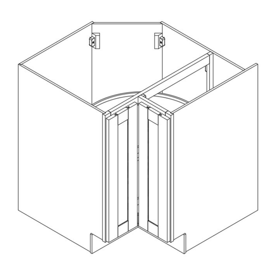
- Page 6 Attach the fixed shelf (I) from Step 2 to the cabinet by maneuvering the tray around the frame then down into position and connecting the cam locks on side panel (D) & back side panel (B). (Figure 7) Figure 7 Install the corner brackets (a) into the top corners shown using screws (c).
- Page 7 Attach hinges (O) with screws (d), and door magnets (g) with screws (b). Install the bumpers (f) to the inside of the doors in the locations shown. (Figure 9) Figure 9 Page 7...
- Page 8 Install the remainder of the door magnets (g) using screws (b) into the full frame using the pre-drilled holes. (Figure 10) Figure 10 Attach the remainder of the hinges (O) using screws (d), and attach the doors by connecting the hinge pieces together. (Figure 11) Figure 11 Page 8...
-
Page 9: Maintenance
►Maintenance For daily cleaning, use a dry cloth and a soft liquid cleaner. Never use abrasive cleaners containing acetone, chlorine or strong bleach. Also, do not use tools as scrapers, metallic brushes, and other products which can scratch or tarnish surfaces. Under no circumstances should you use chrome cleaner on chrome-plated or brass trim, hinges, handles, sockets etc.
Need help?
Do you have a question about the Findley & Myers CB33 and is the answer not in the manual?
Questions and answers