
Subscribe to Our Youtube Channel
Related Manuals for FBR FGP 50/2 EVO-2


Summary of Contents for FBR FGP 50/2 EVO-2
- Page 1 LIGHT-OIL BURNERS AT TWO STAGES FGP 50/2 EVO-2 Installation, use and maintenance instructions 070002_3_B...
-
Page 2: Table Of Contents
_____________________________________________________________ 10 BURNER CALIBRATION _______________________________________________________________ 10 PUMP CALIBRATION ___________________________________________________ 11 TABLE OF ADVISABLE CALIBRATIONS ____________________________________ 11 TABLE OF ADVISABLE CALIBRATIONS FGP 50/2 EVO-2 MAINTENANCE _______________________________________________ 12 EXTRACTION OF THE COMBUSTION HEAD _________________________________________________________ 13 ELECTRODES POSITIONING _______________________________________________________ 14 POSSIBLE CAUSES - SOLUTIONS... -
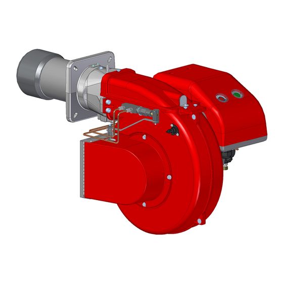
Page 3: Technical Characteristics
** Measured sonourous pressure in the combustion lab, with funcional burner on beta boiler in a distance of 1 m (UNI EN ISO 3746). *** For burner FGP 50/2 EVO-2 with long head add 1 kg to the weight. OPERATING RANGE DIAGRAM FGP 50/2 EVO-2... -
Page 4: Dimensions [Mm]
TECHNICAL CHARACTERISTICS 070002_3_B DIMENSIONS [MM] TC - TL Fig. 2 Dimensions MODEL FGP 50/2 EVO-2 TC - TL: Please see chapter "Flame tube length" FGP 50/2 EVO-2... -
Page 5: Burner Installation
For the installation of the burner to the generator, follow to the diagram shown below: Fig. 3 Burner installation LEGEND 1) Generator 7) Pipe connection 2) Counterflange 8) Screw 3) Stud bolt 9) Burner's body cover 4) ISOMART gasket 10) Screw 5) Washer 11) Head group 6) Nut FGP 50/2 EVO-2... -
Page 6: Burner Signal Description
Press the lockout reset button (pos.2) for about 1 second (<3 seconds). After a non-alterable lockout, the red signal lamp in the lockout reset button (pos.2) lights up. For reset the control box press the lockout reset button (pos.2) for about 1 second (<3 seconds). FGP 50/2 EVO-2... -
Page 7: Installation
WA R NIN G Violation, removal or loss of the data plate of the burner and any other components compromise the correct identification of the burner and hinder the installation and maintenance operation. WA R NIN G FGP 50/2 EVO-2... -
Page 8: Correct Burner Position
L max N min N max FGP 50/2 EVO-2 FLAME TUBE LENGTH Flame tube length must be selected based on the specifications supplied by boiler manufacturer and, in any case, it must be greater than the thickness of the boiler door included its insulation. -
Page 9: Hydraulic System
2nd nozzle (2ND) and at the same time to the jack (pos.4) which causes the opening of the 2nd stage air shutter. ELECTRICAL SYSTEM ELECTRICAL PANEL LAYOUT Please refer to elctrical panel layout supplied with the present Instructions. WORKING DIAGRAM OF THE ELECTRICAL DEVICE Please refer to electrical device handbook supplied with the present Instructions. FGP 50/2 EVO-2... -
Page 10: Start-Up And Calibration
- The ventilation of the boiler location - The correct function of the thermostats and pressure switches of the boiler. PUMP CALIBRATION Fig. 10 Pump calibration LEGEND 1) Delivery 1st stage 2) Delivery 2nd stage 3) Pressure checking 4) Pressure calibration screw FGP 50/2 EVO-2... -
Page 11: Table Of Advisable Calibrations
START-UP AND CALIBRATION 070002_3_B TABLE OF ADVISABLE CALIBRATIONS TABLE OF ADVISABLE CALIBRATIONS FGP 50/2 EVO-2 Calibrations effected with pressure in chambers 0,1 mbar. The definitive calibration must be done in operation by means of a combustion analyser. NOZZLES G.P.H. PRESSURE... -
Page 12: Maintenance
Take off the cover (pos.9) by loosening the 3 screws (pos.10) b) Loosen the connection (pos.7) and the screws (pos.8) c) Take out the head group (pos.11) and pull the ignition cables. Fig. 12 Extraction of the combustion head FGP 50/2 EVO-2... -
Page 13: Electrodes Positioning
MAINTENANCE 070002_3_B ELECTRODES POSITIONING Fig. 13 Electrode positioning LEGEND 1) Disc-Nozzle distance = 8 mm 2) Distance between the electrodes = 4 mm 3) Disc-Electrodes distance = 4 mm FGP 50/2 EVO-2... -
Page 14: Possible Causes - Solutions
5) Closed gate-valve in suction pipe. 5) Open it. 6) Clogged nozzle 6) Disassemble and clean it completely. 7) Motor (three-phase) rotating in the op- 7) Invert a phase in the input switch. posite direction as that indicated by the ar- row. FGP 50/2 EVO-2... - Page 15 5) Adjust them to the prescribed position. distance. 6) Electrodes discharge to earth since they 6) Clean or, if necessary, replace them. are dirty or with a cracked insulation; also check under the clamps fastening the insulating materials. FGP 50/2 EVO-2...
- Page 16 Tel. +39 0442 97000 _ Fax + 39 0442 97299 www. fbr.it _ email: fbr@fbr.it The illustrations and data here shown are indicative. F.B.R. Bruciatori S.r.l. reserves the right to bring, without any obligation of warning, any changes that would be appropriate to the continuing development...
Need help?
Do you have a question about the FGP 50/2 EVO-2 and is the answer not in the manual?
Questions and answers