Table of Contents
Advertisement
Quick Links
Regolatore elettronico per pompe
Electronic regulator for pumps
Elektronikschaltautomat fur Pumpen
Regulateur électonique pour pompes
Regulador electronico para bombas
Ηλεκτρονικός ελεγκτής για αντλίες
Электронный регулятор для насосов
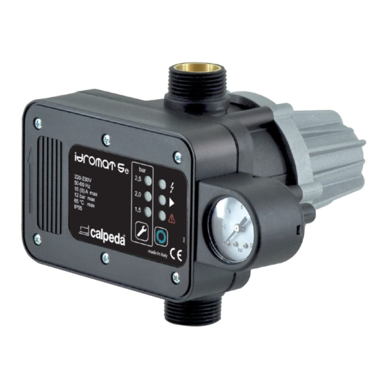
IDROMAT
ISTRUZIONI ORIGINALI PER L'USO
OPERATING INSTRUCTIONS
BETRIEBSANLEITUNG
INSTRUCTIONS POUR L'UTILISATION
INSTRUCCIONES DE USO
INSTRUKTIONER INSTALLATION OG BRUG
ИНСТРУКЦИИ ПО ЭКСПЛУАТАЦИИ
Pagina
2
Page
8
Seite
14
Page
21
Página
27
Side
33
Страница
39
Italiano
English
Deutsch
Français
Español
Danish
Русский
Advertisement
Table of Contents

Related Manuals for Calpeda IDROMAT


Summary of Contents for Calpeda IDROMAT
- Page 1 Regolatore elettronico per pompe Electronic regulator for pumps Elektronikschaltautomat fur Pumpen Regulateur électonique pour pompes Regulador electronico para bombas Ηλεκτρονικός ελεγκτής για αντλίες Электронный регулятор для насосов IDROMAT ISTRUZIONI ORIGINALI PER L'USO Pagina Italiano OPERATING INSTRUCTIONS Page English BETRIEBSANLEITUNG Seite Deutsch INSTRUCTIONS POUR L’UTILISATION...
-
Page 2: General Information
The customer, in case of loss, can request a copy of Operations that must be performed by a the manual by contacting Calpeda S.p.A. specifying the qualified electrician specialised to affect all type of product data shown on the label of the machine... -
Page 3: Technical Description
Pumps control device provided with flow rate and condensation pressure sensor The electronic controller IDROMAT Maximum working rate: 10 m³/h (12 m³/h IDROMAT 6) controls the automatic start and stop of the water pump when opening or closing any tap or valve of the installation. -
Page 4: Transportation And Handling
3.2. Construction 4.2. Safety devices Inlet R1” male (R1” ¼ male for IDROMAT 6) The device has an external case that prevents any Outlet R1” male (R1” ¼ male for IDROMAT 6) contact with internal parts and the elements in voltage. -
Page 5: Installation
It is advisable to connect the device outlet to the system by using a hose. (picture 6) Do not install the Idromat in systems with pumps achieving more than 12 bar pressure at 0 flow. The pressure created by the pump must be normally 1 bar higher than the restarting pressure of the device. -
Page 6: Startup And Operation
1. Be sure that the pump is correctly primed, then methods. (Paragraph 6.7). gently open one tap 2. Connect the IDROMAT to the electric supply, the 8. DISPOSAL voltage LED will lit (POWER 3. The pump starts working automatically and within a Dir. -
Page 7: Troubleshooting
Not enough pump pressure: the security Make sure that the pump pressure is higher system has been activated and the than the starting IDROMAT pressure and that corresponding LED (FAILURE ) is on. the highest point of the plant is lower than the value reported on the technical table. - Page 8 10. SCHEMI DI COLLEGAMENTO ESQUEMAS DE CONEXION CONNECTION DIAGRAMS TILSLUTNINGS DIAGRAMMER ANSCHLUßPLÄNE WEITER UNTEN ΣΧΕΔΙΑΓΡΑΜΜΑ ΣΥΝΔΕΣΗΣ SCHEMA DE RACCORDEMENT СХЕМЫ ДЛЯ ПОДКЛЮЧЕНИЯ DIMENSIONI Figura 1 IDROMAT 5 R1” R1” Figura 2 IDROMAT 6 R 1" 1/4 Made in Italy 110V÷240V 65 °C max 50/60 Hz...
- Page 9 Figura 3 Figura 4 Funzionamento sotto battente Funzionamento in aspirazione Suction lift operation Positive suction head operation Fonctionnement en aspiration Fonctionnement en charge Funcionamiento en aspiración Funcionamiento bajo carga 4.93.096 Valvola di non ritorno 4.93.096/14 Check valve Clapet de non-retour Valvola di non ritorno Valvula de retencion Check valve...
- Page 10 Figura 8 MXA, NGX, NGL Capacità di autoadescamento Self-priming capability Capacitè d’autoamorçage Capacidad de autoaspiraciòn 0,5 m h (mm) ≤ Valvola di non ritorno Check valve Clapet de non-retour Valvula de retencion DN 25 (Øi 28 mm) DN 32 (Øi 36 mm) MXA 205,405 H2O, T = 20°C Pa = 1000 hPa (mbar)
- Page 11 Figura 9 115 V 50-60Hz 230 V 50-60Hz 115 V 50-60Hz 230 V 50-60Hz Figura 10 115 V 50-60Hz > 0,75 kW 230 V 50-60Hz > 1,5 kW Contactor 115 V 50-60Hz 230 V 50-60Hz Figura 11 400 V 50-60Hz 230 V Contactor 400 V 50-60Hz...
- Page 12 GB. DECLARATION OF CONFORMITY We CALPEDA S.p.A. declare that the product IDROMAT, with type and serial number as shown on the name plate, are constructed in accordance with Directives 2011/65/EU, 2014/30/EU, 2014/35/EU and assume full responsability for conformity with the standards laid down therein.
- Page 13 Manufacturer’s Name: Calpeda S.P.A. Address: Via Roggia di Mezzo 39, 36050 Montorso Vicentino (VI) Italy We Calpeda S.P.A. declare that: the undersigned company certifies under its sole responsibility that the pumps specified below satisfy the following requirements of UK regulations.
- Page 14 Calpeda s.p.a. - Via Roggia di Mezzo, 39 - 36050 Montorso Vicentino - Vicenza / Italia Tel. +39 0444 476476 - Fax +39 0444 476477 - E.mail: info@calpeda.it www.calpeda.com...
Need help?
Do you have a question about the IDROMAT and is the answer not in the manual?
Questions and answers