Table of Contents
Advertisement
Available languages
Available languages
Quick Links
Scan for text based
customer support
We appreciate the trust and confidence you have placed in Hampton Bay through the purchase of this ceiling fan. We strive to continually create
quality products designed to enhance your home. Visit us online to see our full line of products available for your home improvement needs.
USE AND CARE GUIDE
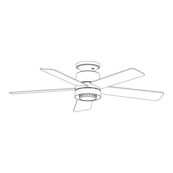
PANACHE 52-INCH CEILING FAN
Questions, problems, missing parts? Before returning to the store,
call Hampton Bay Customer Service
8 a.m. - 7 p.m., EST, Monday-Friday, 9 a.m. - 6 p.m., EST, Saturday
1-855-HD-HAMPTON
To view an instructional video on how to install this product:
1. Go to www.homedepot.com and enter either the Item or Model number, found in the top
right corner of the cover of this instruction manual, in the search eld.
2. Click on your product from the list of search results and click on the video link in the
"Product Overview" section.
Thank you for choosing Hampton Bay!
/
HAMPTONBAY.COM
THANK YOU
UL Model 52-PANA
Scan for online product
warranty information
Item #1008 551 274
Model #92407
Advertisement
Chapters
Table of Contents

Related Manuals for HAMPTON BAY PANACHE 92407


Summary of Contents for HAMPTON BAY PANACHE 92407
- Page 1 THANK YOU We appreciate the trust and confidence you have placed in Hampton Bay through the purchase of this ceiling fan. We strive to continually create quality products designed to enhance your home. Visit us online to see our full line of products available for your home improvement needs.
-
Page 2: Table Of Contents
Table of Contents Table of Contents ..............2 Assembly ................7 Safety Information ............... 2 Operation ................12 Warranty ................3 Care and Cleaning ............. 14 Pre-Installation ..............3 Troubleshooting ..............14 Installation ................6 Safety Information READ AND SAVE THESE INSTRUCTIONS. WARNING: To reduce the risk of personal injury, do not bend the blade brackets (also referred to as flanges) during assembly or after installation. -
Page 3: Warranty
Warranty The supplier warrants the fan motor to be free from defects in workmanship and material present at time of shipment from the factory for a lifetime after the date of purchase by the original purchaser. The supplier warrants that the light kit, excluding any glass, to be free from defects in workmanship and material at the time of shipment from the factory for a period of three years after the date of purchase by the original purchaser. - Page 4 Pre-Installation (continued) HARDWARE INCLUDED NOTE: Hardware not shown to actual size. Part Description Quantity Plastic wire connecting nuts Blade screw Machine screw Short tapered screw Long tapered screw...
- Page 5 Pre-Installation (continued) PACKAGE CONTENTS Part Description Quantity Part Description Quantity Mounting plate Light kit shade Trim ring Receiver Fan motor assembly Remote control Blade Battery Remote control cradle with toggle Light kit pan switch spacer included Light kit assembly IMPORTANT: This product and/or components are governed by one or more of the following U.S.
-
Page 6: Installation
Installation MOUNTING OPTIONS WARNING: To reduce the risk of fire, electric shock or personal injury, mount to outlet box marked “Acceptable for fan support of 35 lb (15.9 kg) or less”, and use screws provided with the outlet box. An outlet box commonly used for the support of lighting fixtures may not be acceptable for fan support and may need to be replaced. -
Page 7: Assembly
Assembly - Hanging the Fan Attaching the mounting plate Hanging the fan motor assembly to the electrical box □ Attach the trim ring (B) to the fan motor assembly (C) at the WARNING: To avoid possible electrical shock, turn the opening of the motor housing. - Page 8 Assembly - Hanging the Fan (continued) Making the electrical connections Installing the receiver WARNING: To reduce the risk of fire or electric shock, remember WARNING: Each wire nut supplied with this fan is designed to disconnect power. The electrical wiring must meet all local to accept up to one 12-gauge house wire and two wires and national electrical code requirements.
- Page 9 Assembly - Hanging the Fan (continued) Installing the motor assembly □ Remove two of the four screws (located diagonally from each other) (NN) from the top of the mounting plate (A) and loosen the other two screws (NN). □ Align the two key slots in the top of the fan motor assembly (C) with the two loosened screws (NN) on the mounting plate (A).
- Page 10 Assembly - Attaching the Light Kit Installing the light kit pan □ Remove one screw (LL) from the black bracket below the fan motor assembly (C), and loosen but do not remove the other two screws. □ Push the light kit pan (E) up to the fan motor assembly (C) so that the two loosened screw heads fit into the keyhole slots.
- Page 11 Assembly - Mounting the remote wall cradle NOTE: The remote wall cradle is designed to allow you to access an existing switch. The remote wall cradle can be mounted on the wall or to the face plate of a standard toggle switch or a paddle switch.
- Page 12 Pairing multiple remote controls to one ceiling fan NOTE: The fan can be controlled by up to three remote controls. To order extra remote controls, please call Hampton Bay customer service 1-855-HD-HAMPTON. NOTE: The fan can only be controlled by 3 remote controls maximum at the same time after “Learning”.
- Page 13 Operating Your Remote Control Remote Control - Your fan is equipped with a remote control to operate the speed and lights of your new ceiling fan. LED SPEED INDICATOR LEDs will illuminate to the corresponding speed: 1 Light - Low 2 Lights - Medium 3 Lights - High LED speed...
-
Page 14: Care And Cleaning
Care and Cleaning WARNING: Make sure the power is off before cleaning your fan. □ Because of the fan’s natural movement, some connections may become loose. Check the support connections, brackets, and blade attachments twice a year. Make sure they are secure. It is not necessary to remove the fan from the ceiling. □... - Page 15 Questions, problems, missing parts? Before returning to the store, call Hampton Bay Customer Service 8 a.m. - 7 p.m., EST, Monday-Friday, 9 a.m. - 6 p.m., EST, Saturday 1-855-HD-HAMPTON HAMPTONBAY.COM Retain this manual for future use. Scan for text based...
- Page 16 GRACIAS POR TU COMPRA Apreciamos la plena confianza que has depositado en Hampton Bay con la compra de este ventilador de techo. Nos esforzamos constantemente por crear productos de calidad diseñados para tu hogar. Visítanos por Internet para ver nuestra línea completa de productos disponibles a fin de satisfacer tus necesidades de mejoras del hogar.
- Page 17 Tabla de contenido Tabla de contenido .............. 2 Ensamblaje ................7 Información de seguridad........... 2 Funcionamiento ..............12 Garantía ................3 Mantenimiento y limpieza ..........14 Preinstalación ..............3 Solución de problemas ............. 14 Instalación ................6 Información de seguridad LEE Y GUARDA ESTAS INSTRUCCIONES.
-
Page 18: Garantía
Garantía El proveedor garantiza de por vida, a partir de la fecha de adquisición por el comprador original, que el motor del ventilador no presenta defectos de fabricación ni de materiales al momento del envío desde la fábrica. El proveedor garantiza que el kit de luces, excluyendo cualquier vidrio, no tendrá defectos de fabricación ni de material en el momento del envío desde la fábrica por un período de tres años después de la fecha de compra por parte del comprador original. - Page 19 Preinstalación (continuación) HERRAJES INCLUIDOS NOTA: Los herrajes no se muestran en tamaño real. Pieza Descripción Cantidad Tuercas plásticas de conexión de cables Tornillo de aspa Tornillo de la unidad Tornillo cónico corto Tornillo cónico largo...
- Page 20 Preinstalación (continuación) CONTENIDO DEL PAQUETE Pieza Descripción Cantidad Pieza Descripción Cantidad Placa de montaje Pantalla del kit de luces Aro de la moldura Receptor Conjunto del motor del ventilador Control remoto Aspa Batería Soporte del control remoto con Carcasa del kit de luces separador de interruptor de palanca Ensamblaje del kit de luces incluido...
-
Page 21: Instalación
Instalación OPCIONES DE MONTAJE ADVERTENCIA: Para reducir el riesgo de incendio, descarga eléctrica o lesiones personales, instala solo en una caja eléctrica clasificada como “apropiada para sostener ventiladores de 35 lb (15.9 kg) o menos” y usa los tornillos que vienen con ella. Las cajas eléctricas utilizadas comúnmente para el soporte de lámparas pueden no servir como soporte de ventilador y tal vez deban reemplazarse. - Page 22 Ensamblaje - Cómo colgar el ventilador Cómo fijar el ventilador a la Cómo colgar el ensamblaje del motor placa de montaje del ventilador □ Fija el aro de la moldura (B) al conjunto del motor del ventilador (C) ADVERTENCIA: Para evitar una posible descarga eléctrica, en la abertura de la carcasa del motor.
-
Page 23: Ensamblaje
Ensamblaje - Cómo colgar el ventilador (continuación) Cómo hacer las conexiones eléctricas Cómo instalar el receptor ADVERTENCIA: Cada tuerca para cable suministrada con este ADVERTENCIA: Para reducir el riesgo de incendio o descarga ventilador está diseñada para aceptar un cable doméstico de eléctrica, recuerda desconectar la electricidad. - Page 24 Ensamblaje - Cómo colgar el ventilador (continuación) Cómo instalar el conjunto ensamblado del motor □ Quita dos de los cuatro tornillos (ubicados en diagonal uno de otro) (NN) de la parte superior de la placa de montaje (A) y afloja los otros dos (NN). □...
- Page 25 Ensamblaje - Cómo instalar el kit de luces Cómo instalar la carcasa del kit de luces □ Quita un tornillo (LL) del soporte negro bajo el conjunto motor- ventilador (C) y afloja los otros dos tornillos, pero sin quitarlos. □ Empuja la carcasa del kit de luces (E) hacia el conjunto motor- ventilador (C) de manera que las cabezas de los dos tornillos aflojados encajen en los orificios tipo ojo de cerradura.
- Page 26 Ensamblaje - Montaje del soporte remoto de pared NOTA: El soporte de pared remoto está diseñado para permitirte acceder a un interruptor existente. El soporte de pared remoto puede montarse en la pared o en la placa frontal de un interruptor de palanca estándar o de un interruptor de paleta.
- Page 27 NOTA: El ventilador se puede controlar con hasta tres controles remotos. Para pedir controles remotos adicionales, llama al servicio de atención al cliente de Hampton Bay al Servicio al 1-855-HD-HAMPTON. NOTA: El ventilador sólo puede ser controlado por 3 controles remotos como máximo al mismo tiempo después del "Aprendizaje".
- Page 28 Cómo usar el control remoto Control remoto - Tu ventilador está equipado con un control remoto que controla la velocidad y las luces. INDICADOR LED DE VELOCIDAD Las luces LED se iluminarán a la velocidad correspondiente: 1 luz: baja 2 luces: media 3 luces: alta TODO Indicador LED...
-
Page 29: Mantenimiento Y Limpieza
Mantenimiento y limpieza ADVERTENCIA: Asegúrate de que la corriente esté apagada antes de limpiar el ventilador. □ Debido al movimiento natural del ventilador, algunas conexiones pueden aflojarse. Revisa dos veces al año las conexiones de soporte, los soportes y los accesorios de las aspas. Comprueba que estén seguros. No es necesario desmontar el ventilador del techo. □... - Page 30 ¿Preguntas, problemas, piezas faltantes? Antes de devolverlo a la tienda, llama al Servicio al Cliente de Hampton Bay de lunes a viernes, entre 8:00 a.m. a 7:00 p.m. (hora del Este), y los sábados de 9:00 a.m. a 6:00 p.m. (hora del Este) 1-855-HD-HAMPTON HAMPTONBAY.COM...
Need help?
Do you have a question about the PANACHE 92407 and is the answer not in the manual?
Questions and answers