Table of Contents
Advertisement
Available languages
Available languages
Quick Links
Scan for text based
customer support
We appreciate the trust and confidence you have placed in Hampton Bay through the purchase of this ceiling fan. We strive to continually create
quality products designed to enhance your home. Visit us online to see our full line of products available for your home improvement needs.
USE AND CARE GUIDE
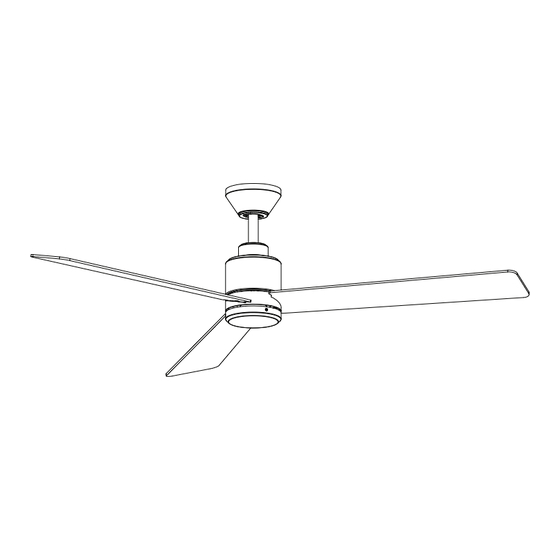
HERMON 60-INCH CEILING FAN
Questions, problems, missing parts? Before returning to the store,
call Hampton Bay Customer Service
8 a.m. - 7 p.m., EST, Monday-Friday, 9 a.m. - 6 p.m., EST, Saturday
1-855-HD-HAMPTON
To view an instructional video on how to install this product:
1. Go to www.homedepot.com and enter either the Item or Model number, found in the top
right corner of the cover of this instruction manual, in the search eld.
2. Click on your product from the list of search results and click on the video link in the
"Product Overview" section.
Thank you for choosing Hampton Bay!
/
HAMPTONBAY.COM
THANK YOU
Item #1010 158 077
UL Model #60-CHAN
Scan for online product
warranty information
Model #90382
Advertisement
Chapters
Table of Contents

Subscribe to Our Youtube Channel
Related Manuals for HAMPTON BAY HERMON 90382


Summary of Contents for HAMPTON BAY HERMON 90382
- Page 1 THANK YOU We appreciate the trust and confidence you have placed in Hampton Bay through the purchase of this ceiling fan. We strive to continually create quality products designed to enhance your home. Visit us online to see our full line of products available for your home improvement needs.
-
Page 2: Table Of Contents
Table of Contents Table of Contents ..............2 Assembly ................7 Safety Information ............... 2 Operating Your Fan and Remote Control ......13 Warranty ................3 Care and Cleaning ............. 15 Pre-Installation ..............3 Troubleshooting ..............15 Installation ................6 Safety Information READ AND SAVE THESE INSTRUCTIONS. -
Page 3: Warranty
“wobble” is normal and should not be considered a defect. Servicing performed by unauthorized persons shall render the warranty invalid. There is no other express warranty. Hampton Bay hereby disclaims any and all warranties, including but not limited to those of merchantability and fitness for a particular purpose to the extent permitted by law. - Page 4 Pre-Installation (continued) HARDWARE INCLUDED NOTE: Hardware not shown to actual size. Part Description Quantity Blade attachment screws Wire connecting nut Hanger pin Locking pin Machine screw Short tapered screw Long tapered screw...
- Page 5 Pre-Installation (continued) PACKAGE CONTENTS Part Description Quantity Part Description Quantity Slide-on mounting bracket Light kit pan (inside canopy) Bottom plate Ball/downrod assembly Receiver Canopy Remote control Decorative motor collar cover 66 in. extension wire Fan motor assembly Battery Blade Remote control cradle with toggle switch spacer included IMPORTANT: This product and/or components are governed by Blade support plate...
-
Page 6: Installation
Installation MOUNTING OPTIONS NOTE: You may need a longer downrod to maintain WARNING: To reduce the risk of fire, electric shock proper blade clearance when installing on a steep, sloped or personal injury, mount to an outlet box marked ceiling. The maximum angle allowable is 20° away from “Acceptable for fan support of 35 lb (15.9 kg) or less”, horizontal. - Page 7 Assembly - Standard Ceiling Mount Preparing for mounting □ Remove the magnetic canopy bottom cover (JJ) from the canopy (C) by pulling it off. □ Loosen the two canopy screws (HH) located in the bottom of the mounting bracket (A). □...
- Page 8 Assembly - Hanging the Fan Attaching the fan to the electrical box WARNING: To reduce the risk of fire, electric shock or personal injury, mount to an outlet box marked “Acceptable for fan support of 35 lb (15.9 kg) or less”, and use screws provided with the outlet box.
-
Page 9: Assembly
Assembly - Hanging the Fan (continued) Installing the receiver WARNING: To reduce the risk of fire or electric shock, remember to disconnect power. The electrical wiring must meet all local and national electrical code requirements. The electrical source and fan must be 110/120 volts, 60Hz. - Page 10 Assembly - Hanging the Fan (continued) Wiring the fan to the receiver Outlet box NOTE: The fan comes with 8 in. lead wires for use with the provided 6 in. ball/downrod assembly (B). If you wish to use Green a longer downrod, attach the 66 in. extension wire (K) to the fan by connecting the molded adaptor plugs from the extension wires to the adaptor plug from the fan.
- Page 11 Assembly - Attaching the Fan Blades Attaching the fan blades □ Attach a blade (F) to the fan motor assembly (E) by inserting the blade (F) and blade support plate (N) into the slots in the side of the fan motor assembly (E) and aligning the three screw holes in the blade support plate (N) and blade (F) with the holes in the center flywheel.
- Page 12 Pairing multiple remote controls to one ceiling fan NOTE: The fan can be controlled by up to three remote controls. To order extra remote controls, please call Hampton Bay customer service 1-855-HD-HAMPTON. NOTE: The fan can only be controlled by 3 remote controls maximum at the same time after “Learning”.
-
Page 13: Operating Your Fan And Remote Control
Operating Your Fan and Remote Control NOTE: On start up your ceiling fan will oscillate back and forth. This is NORMAL OPERATION for DC ceiling fans as it goes LED speed through its calibration cycle. The fan is NOT DEFECTIVE. indicator NOTE: The remote receiver includes a memory function that will return the fan to its last setting when turned on via the power... - Page 14 Assembly - Mounting the remote wall cradle NOTE: The remote wall cradle is designed to allow you to access an existing switch. The remote wall cradle can be mounted on the wall or to the face plate of a standard toggle switch or a paddle switch.
-
Page 15: Care And Cleaning
Care and Cleaning WARNING: Make sure the power is off before cleaning your fan. □ Because of the fan’s natural movement, some connections may become loose. Check the support connections, brackets, and blade attachments twice a year. Make sure they are secure. It is not necessary to remove the fan from the ceiling. □... - Page 16 Questions, problems, missing parts? Before returning to the store, call Hampton Bay Customer Service 8 a.m. – 7 p.m., EST, Monday – Friday, 9 a.m. – 6 p.m., EST, Saturday 1-855-HD-HAMPTON HAMPTONBAY.COM Retain this manual for future use. Scan for text based...
- Page 17 GRACIAS POR TU COMPRA Apreciamos la plena confianza que has depositado en Hampton Bay al comprar este ventilador de techo. Nos esforzamos en crear continuamente productos de calidad diseñados para mejorar tu hogar. Visítanos por Internet para ver nuestra línea completa de productos disponibles para tus...
- Page 18 Tabla de contenido Tabla de contenido .............. 2 Ensamblaje ................7 Información de seguridad........... 2 Cómo usar el ventilador y el control remoto ....13 Garantía ................3 Mantenimiento y limpieza ..........15 Preinstalación ..............3 Solución de problemas ............. 15 Instalación ................
-
Page 19: Garantía
Cierta “oscilación” es normal y no debe considerase un defecto. Cualquier servicio prestado por personal no autorizado invalidará la garantía. No hay ninguna otra garantía expresa. Por este medio y en el alcance permitido por la ley, Hampton Bay queda exonerado de toda garantía, incluso, pero sin limitarse a ellas, aquellas de comercialización e idoneidad para un fin determinado. - Page 20 Preinstalación (continuación) HERRAJES INCLUIDOS NOTA: Los herrajes no se muestran en tamaño real. Pieza Descripción Cantidad Tornillos para fijar aspas Tuerca para conectar cables Pasador de soporte Pasador de cierre Tornillo maquinado Tornillo cónico corto Tornillo cónico largo...
- Page 21 Preinstalación (continuación) CONTENIDO DEL PAQUETE Pieza Descripción Cantidad Pieza Descripción Cantidad Soporte de montaje deslizante Carcasa del kit de luces (dentro de la cubierta) Placa inferior Conjunto de tubo bajante/esfera Receptor Cubierta Control remoto Cubierta decorativa del collarín del motor Cable de extensión de 66 pulgadas (167 cm) Conjunto del motor del ventilador Batería...
-
Page 22: Instalación
Instalación OPCIONES DE MONTAJE NOTA: Tal vez necesites un tubo bajante más largo para ADVERTENCIA: Para reducir el riesgo de incendio, mantener la altura mínima adecuada de las aspas al descarga eléctrica o lesiones personales, instala solo instalar el ventilador en un techo inclinado. El ángulo en una caja eléctrica clasificada como “Apropiada para máximo permitido es 20º... - Page 23 Ensamblaje - Montaje estándar en techo Preparación para el montaje □ Retira la tapa inferior magnética (JJ) de la cubierta (C), tirando de ella hasta soltarla. □ Afloja los dos tornillos de la cubierta (HH) ubicados en la parte inferior del soporte de montaje (A). □...
- Page 24 Ensamblaje - Cómo colgar el ventilador Cómo fijar el ventilador a la caja eléctrica ADVERTENCIA: Para reducir el riesgo de incendio, descarga eléctrica o lesiones personales, instala solo en una caja eléctrica clasificada como “Apropiada para sostener ventiladores de 35 lb (15.9 kg) o menos” y usa los tornillos incluidos con la caja eléctrica.
-
Page 25: Ensamblaje
Ensamblaje - Cómo colgar el ventilador (continuación) Cómo instalar el receptor ADVERTENCIA: Para reducir el riesgo de incendio o descarga eléctrica, recuerda desconectar la electricidad. El cableado eléctrico tiene que cumplir todos los requisitos de los códigos eléctricos nacionales y locales. La fuente de energía y el ventilador tienen que ser de 110/120 V y 60 Hz. - Page 26 Ensamblaje - Cómo colgar el ventilador (continuación) Cómo cablear el ventilador al receptor Caja eléctrica NOTA: El ventilador viene con cables terminales de 8 plg (20.3 cm) para usar con el conjunto de tubo bajante/esfera (B) Verde de 6 plg (15.2 cm) incluido. Si deseas utilizar un tubo bajante más largo, conecta el cable de extensión de 66 pulgadas [1.7 m] (K) al ventilador conectando los enchufes adaptadores moldeados de los cables de extensión a los enchufes...
- Page 27 Ensamblaje - Cómo fijar las aspas del ventilador Cómo fijar las aspas del ventilador □ Fija un aspa (F) al ensamblaje del motor del ventilador (E) insertando el aspa (F) y la placa de soporte del aspa (N) en las ranuras en el costado del ensamblaje del motor del ventilador (E) y alineando los tres orificios para tornillos en la placa de soporte de la aspa (N) y la aspa (F) con los orificios en el volante central.
- Page 28 NOTA: El ventilador se puede controlar con hasta tres controles remotos. Para pedir controles remotos adicionales, llama a Servicio al Cliente de Hampton Bay al 1-855-HD-HAMPTON. NOTA: El ventilador sólo puede ser controlado por 3 controles remotos como máximo al mismo tiempo después del "Aprendizaje".
- Page 29 Cómo usar tu ventilador y control remoto NOTA: Al comenzar, tu ventilador de techo oscilará hacia adelante y hacia atrás. Esto es un FUNCIONAMIENTO NORMAL Velocidad LED del ventilador de techo de CC, ya que realiza un ciclo de indicador calibración.
- Page 30 Ensamblaje - Montaje del soporte de pared para control remoto NOTA: El soporte de pared para control remoto está diseñado para permitirte acceder a un interruptor existente. El soporte de pared para control remoto puede montarse en la pared o en la placa frontal de un interruptor de palanca estándar o de un interruptor de paleta.
-
Page 31: Mantenimiento Y Limpieza
Mantenimiento y limpieza ADVERTENCIA: Asegura que la fuente de corriente está apagada antes de limpiar el ventilador. □ Debido al movimiento natural del ventilador, algunas conexiones pueden aflojarse. Revisa dos veces al año las conexiones de soporte, los soportes y los accesorios de las aspas. Comprueba que estén seguros. No es necesario desmontar el ventilador del techo. □... - Page 32 ¿Preguntas, problemas, piezas faltantes? Antes de devolver a la tienda, llama al Servicio al Cliente de Hampton Bay de lunes a viernes de 8:00 a.m. a 7:00 p.m. (Hora del Este) o los sábados de 9:00 a.m. a 6:00 p.m. (Hora del Este.
Need help?
Do you have a question about the HERMON 90382 and is the answer not in the manual?
Questions and answers