Leviton EZ-MAX H Series Quick Start Manual
Lighting control panel relays
Hide thumbs
Also See for EZ-MAX H Series:
- Installation manual (20 pages) ,
- Installation manual (17 pages) ,
- Manual (2 pages)
Table of Contents
Advertisement
Quick Links
WARNINGS:
• TO AVOID FIRE, SHOCK OR DEATH: TURN OFF POWER AT CIRCUIT BREAKER OR FUSE AND TEST THAT
THE POWER IS OFF BEFORE WIRING!
• TO AVOID PERSONAL INJURY OR PROPERTY DAMAGE, DO NOT install to control a receptacle, or a load in
excess of the specified rating.
• Always disconnect the power supply from the panel's main board prior to making any connections between relay
boards and the main board. Failure to do so, may result in personal injury, damage to the panel, and void its warranty.
• To be installed and/or used in accordance with electrical codes and regulations.
• Must be installed by electrician or other qualified personnel.
• A disconnect switch or a circuit breaker must be provided and marked as the disconnecting device.
• The use of accessory equipment, not recommended by the manufacturer, may cause an unsafe condition.
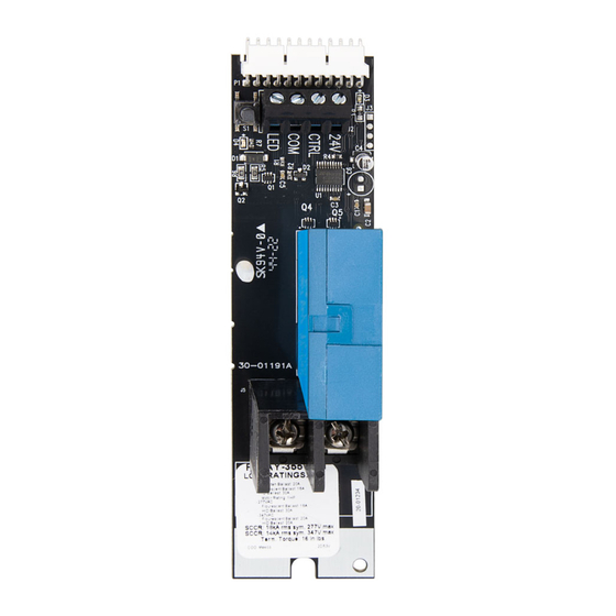
Product Description
H Series' relays are designed to be installed in EZ-MAX H Series panels only. Individual
relays of any type can be placed in any position in the panel. Two pole relays fit in the
same space as one pole relays.
Installing Individual Relay Cards
WARNING: TO AVOID FIRE, SHOCK OR DEATH, turn OFF power at circuit breaker or
fuse and test that the power is off before wiring.
1. Disconnect the low voltage control input plug, which is located at the top of the
main board.
2. Align the relay board in the desired relay position and insert the relay card plug
connector (male) into the socket (female) on the main board.
NOTE: Make sure all of the pins line up, and the connection is tight.
3. Insert and tighten the relay card mounting screw.
NOTE: Do not over tighten the relay card mounting screw with a high-amount of torque
force, as this can loosen the relay card plug connector.
Connecting Lighting Loads
CAUTION: Prior to making any connections to the relay outputs, verify that none of the
loads have shorted. Failure to do so, may result in personal injury, damage to the panel,
and void its warranty.
1. Turn the power OFF.
2. Route the lighting system line and load leads through the high-voltage area of the panel.
3. Connect line and load leads for each lighting load to the output terminals of the
appropriate relay, as delineated in the project plans or panel load schedule. Space is
provided for the circuit identification number to be written adjacent to the terminals on
each relay card.
NOTE: If no panel load schedule exists, use the panel load schedule form supplied in the
clear plastic pocket inside the panel door to record the lighting circuit relay assignments,
while connecting the relay.
EZ-MAX™ H SERIES - Lighting Control Panel Relays
INSTALLATION INSTRUCTIONS
Cat. No. RELAY
CAUTIONS:
• If any emergency circuits are fed or controlled from this panel, they must be located electrically where fed. For
example, from a UPS, generator, or other guaranteed power source during emergency and power outage situations.
• If the equipment is used in a manner not specified by the manufacturer, the protection provided by the equipment
may be impaired.
• For indoor use only.
• DO NOT mount near gas or electric heaters.
• No user serviceable components. DO NOT attempt to service or repair.
• Use this device WITH COPPER OR COPPER-CLAD WIRE ONLY.
Connecting Low Voltage Input
Bring the low-voltage wiring for the contact inputs in through the knockouts in the low-
voltage wiring area. The EZ-MAX H Series relay card includes one input. The input is
software, which you can configure via programming to support momentary switches,
maintained switches (latching), motion sensors, or photocells. The input may be connected
prior to programming. Inputs may be connected to any terminal location, regardless of final
control programming. Connect contact closure input devices to the input terminals using
#18 AWG wire.
NOTE: Use the panel load schedule form, supplied in the clear plastic pocket inside the
panel door, to record the low voltage input types while making connections.
The Low Voltage Control diagrams, shown below, are for use with Leviton low-voltage input
devices ONLY.
Photocell
N
H
Occupancy Sensor
Hot (Black)
Line
120/277/347VAC
60Hz
Neutral (White)
Low Voltage Switch
Low Voltage Switch
with LED
Gray 1-10V Dim Out
Violet 1-10V Dim Out
LOAD
LOAD
Gray 1-10V Dim Out
Blue
White
OPP20-RD3
Gray
Black
Blue
Blue
Red
Black
NC-Brown
Common-Green
NO-Brown/White
Red (24VDC)
Black
Red
Blue
(Control)
Black
Blue
Blue
Red
Blue
Black
Black
Blue
White
Terminal Blocks
Switch
Common
PK-A3453-10-00-0A
ENGLISH
Violet 1-10V Dim Out
Orange
Red
Black
ODC0P-D0W
Low Voltage Photocell
Blue
Red
Black
Occupancy Sensor
Sensor
To HVAC
System
Gray*
Black
Load
Gray*
White
Advertisement
Table of Contents

Related Manuals for Leviton EZ-MAX H Series


Summary of Contents for Leviton EZ-MAX H Series
- Page 1 Product Description Connecting Low Voltage Input H Series' relays are designed to be installed in EZ-MAX H Series panels only. Individual Bring the low-voltage wiring for the contact inputs in through the knockouts in the low- relays of any type can be placed in any position in the panel. Two pole relays fit in the voltage wiring area.
- Page 2 LIMITED 5 YEAR WARRANTY AND EXCLUSIONS Leviton warrants to the original consumer purchaser and not for the benefit of anyone else that this product at the time of its sale by Leviton is free of defects in materials and workmanship under normal and proper use for five years from the purchase date.
Need help?
Do you have a question about the EZ-MAX H Series and is the answer not in the manual?
Questions and answers