Table of Contents
Advertisement
Quick Links
Z
10-Gigabit Web Smart Switch - 10-Port
Installation and Getting Started Guide
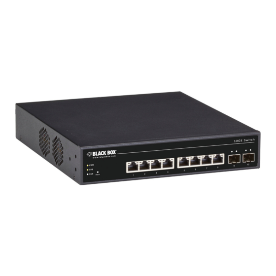
• Has eight 100M/1G/10G twisted-pair ports and two slots for SFP+
modules.
Customer
Support
Information
Order toll-free in the U.S.: Call 877-877-BBOX (outside U.S. call 724-746-5500)
FREE technical support 24 hours a day, 7 days a week: Call 724-746-5500 or fax 724-746-0746
www.blackbox.com • info@blackbox.com
LGB5510A
Advertisement
Table of Contents

Subscribe to Our Youtube Channel
Related Manuals for Black Box LGB5510A


Summary of Contents for Black Box LGB5510A
- Page 1 LGB5510A 10-Gigabit Web Smart Switch - 10-Port Installation and Getting Started Guide • Has eight 100M/1G/10G twisted-pair ports and two slots for SFP+ modules. Order toll-free in the U.S.: Call 877-877-BBOX (outside U.S. call 724-746-5500) Customer FREE technical support 24 hours a day, 7 days a week: Call 724-746-5500 or fax 724-746-0746 Support www.blackbox.com •...
- Page 2 Trademarks Used in this Manual Trademarks Used in this Manual Black Box and the Double Diamond logo are registered trademarks of BB Technologies, Inc. Any other trademarks mentioned in this manual are acknowledged to be the property of the trademark owners.
- Page 3 Disclaimer: Black Box Network Services shall not be liable for damages of any kind, including, but not limited to, punitive, consequential or cost of cover damages, resulting from any errors in the product information or specifications set forth in this document and Black Box Network Services may revise this document at any time without notice.
- Page 4 NOM Statement Instrucciones de Seguridad (Normas Oficiales Mexicanas Electrical Safety Statement) 1. Todas las instrucciones de seguridad y operación deberán ser leídas antes de que el aparato eléctrico sea operado. 2. Las instrucciones de seguridad y operación deberán ser guardadas para referencia futura. 3.
- Page 5 Safety Information Safety Information CAUTION: Circuit devices are sensitive to static electricity, which can damage their delicate electronics. Dry weather conditions or walking across a carpeted floor may cause you to acquire a static electrical charge. To protect your device, always: •...
-
Page 6: Table Of Contents
6.9 10-Gbps Gigabit Ethernet Collision Domain ........................23 7. Cable Labeling and Connection Records ..........................24 8. Troubleshooting ...................................25 8.1 Basic Troubleshooting Tips ............................25 8.2 Contacting Black Box..............................26 8.3 Shipping and Packaging ..............................26 9. Power and Cooling Problems ..............................27 9.1 Installation ...................................27 9.2 In-Band Access ................................27... -
Page 7: Specifications
Chapter 1: Specifications 1. Specifications Compliances Emissions EN55022 (CISPR 22) Class A EN 61000-3; FCC Class A; CE Mark Immunity EN 61000-4-2/3/4/5/6/8/11; EN 55024 Environmental Operating Temperature +32 to +122° F (0 to +50° C) Operating Humidity 10% to 90% (non-condensing) Management Spanning Tree Protocol (STP) Standard Spanning Tree 802.1d;... - Page 8 Chapter 1: Specifications Physical Connectors (8) 10-Gbps RJ-45 twisted-pair ports; (2) empty slots for SFP+ fiber modules; (1) 3-prong power connector Indicators (LEDs) TP Ports: (8) Status (LINK/ACT) LEDs, (8) 100M/1G/10G LEDs; SFP+ Ports: (2) Status (LINK/ACT/SPD) LEDs, (2) 1G/10G LEDs; (1) Power LED Network Interface Ports 1-8:...
-
Page 9: Overview
The LGB5510A switch has 10 ports for 10-Gigabit Ethernet connectivity. However, unlike other entry-level switching solutions that provide advance managed network capabilities only in the costliest models, the LGB5510A switch supports advanced security management capabilities and network features, including data, voice, security, and wireless technologies. -
Page 10: Hardware Description
Chapter 2: Overview If you have any trouble accessing the Black Box site to download the manual, you can contact our Technical Support at 724-746-5500 or info@blackbox.com. 2.4 Hardware Description The switch has eight 10GBASE-T RJ-45 ports. All RJ-45 ports support automatic MDI/MDI-X operation, auto-negotiation and IEEE 802.3x auto-negotiation of flow control, so the optimum data rate and transmission can be selected automatically. - Page 11 Chapter 2: Overview Table 2-1. Switch components. Number in Figure 2-1 Component Condition Description or 2-2 System Status LEDs (1) Power LED Green Lights green when power is on to the switch. OFF when there is no power to the switch. (1) System LED Green Lights green when the system is ready.
-
Page 12: Network Planning
3.2 Application Examples The LGB5510A Switch has eight 10-Gigabit Ethernet TP ports with auto MDI-X and two slots for removable SFP+ modules that support comprehensive types of fiber connection, such as LC and BiDi-LC modules. It is not only designed to segment your network, but also to provide a wide range of options in setting up network connections. -
Page 13: Installing The Switch
• Make sure the twisted-pair Ethernet cable is always routed away from power lines, radios, transmitters, or any other source of electrical interference. • Make sure that LGB5510A Switch is connected to a separate grounded power outlet that provides 100 to 240 VAC, 50 to 60 Hz. - Page 14 Chapter 4: Installing the Switch • Mechanical Loading: Do not place any equipment on top of a rackmounted unit. • Circuit Overloading: Do not overload the supply circuit to the rack assembly. • Grounding: Properly ground rackmounted equipment. To rackmount devices: Step 1: Attach the brackets to the device using the screws provided.
-
Page 15: Wallmounting
Chapter 4: Installing the Switch Step 3: If you are installing a single switch only, turn to Section 4.6, Connecting to a Power Source at the end of this chapter. Step 4: If installing multiple switches, mount them in the rack, one below the other, in any order. 4.4.2 Wallmounting To wallmount the switch: Step 1: Drill two holes (2.7-mm deep) through the wall with the drill (4.4-mm to 6.8-mm in diameter). -
Page 16: Desktop Or Shelf Mounting
Chapter 4: Installing the Switch 4.4.3 Desktop or Shelf Mounting To mount the switch on a desktop or shelf: Step 1: Attach the four adhesive rubber feet to the bottom of the first switch. Figure 4-4. Attaching the adhesive rubber feet. Step 2: Set the device on a flat surface near an AC power source, Make sure there are at least two inches of space on all sides for proper airflow. - Page 17 Chapter 4: Installing the Switch Figure 4-5. Inserting an SFP+ transceiver module into a slot on the switch. The SFP+ slots support the following optional SFP+ transceivers shown in Table 4-1. Table 4-1. Compatible SFP+ transceiver modules. Part Number Description LFP411 SFP/1250 Extended Diagnostics, LC multimode, 850 nm, 550 m LFP412...
-
Page 18: Connecting To A Power Source
Chapter 4: Installing the Switch 4.6 Connecting to a Power Source You can plug or remove power cord from AC power socket, to switch the power on and off. Figure 4-6. Inserting the power cord into the AC socket. Step 1: Insert the power cable plug directly into the AC socket located on the back of the switch. Step 2: Plug the other end of the cable into a grounded, 3-pin, AC power source. -
Page 19: Operation Of Web-Based Management
Default Gateway: 192.168.1.254 Username: admin Password: To access the web management of the LGB5510A switch, enter the default IP Address in a Web browser and press enter. For example: http://192.168.1.1 Once you have entered the IP address into the web browser you will be prompted to enter a username and password so you can access the web management interface. -
Page 20: Making Network Connections
Chapter 6: Making Network Connections 6. Making Network Connections 6.1 Connecting Network Devices The switch is designed to be connected to 100M, 1G, 10Gbps network cards in PCs and servers, as well as to other switches and hubs. It may also be connected to remote devices using optional SFP+ transceivers. 6.2 Twisted-Pair Devices Each device requires an unshielded twisted-pair (UTP) cable with RJ-45 connectors at both ends. -
Page 21: Fiber Optic Sfp+ Devices
Chapter 6: Making Network Connections Equipment rack (side view) Switch Patch-down block Patch Panel Wall Figure 6-2. Network wiring connections. 6.6 Fiber Optic SFP+ Devices An optional 10Gigabit SFP+ transceiver can be used for a backbone connection between switches, or for connecting to a high- speed server. -
Page 22: Connectivity Rules
Chapter 6: Making Network Connections Figure 6-3. Making fiber port connections. Step 4: As a connection is made, check the Link LED on the switch corresponding to the port to be sure that the connection is valid. 6.7 Connectivity Rules When adding hubs to your network, note that because switches break up the path for connected devices into separate collision domains, you should not include the switch or connected cabling in your calculations for cascade length involving other devices. -
Page 23: 10-Gbps Gigabit Ethernet Collision Domain
Chapter 6: Making Network Connections 6.9 10-Gbps Gigabit Ethernet Collision Domain Table 6-1. Maximum cable lengths. 10GBASE-T Gigabit Ethernet cable. Cable Type Maximum Cable Length Connector Category 6a 100-ohm UTP or STP 328 ft. (100 m) RJ-45 1000BASE-T Gigabit Ethernet cable. Cable Type Maximum Cable Length Connector... -
Page 24: Cable Labeling And Connection Records
Chapter 7: Cable Labeling and Connection Records 7. Cable Labeling and Connection Records When planning a network installation, it is essential to label the opposing ends of cables and to record where each cable is connected. This will allow users to easily locate inter-connected devices, isolate faults, and change your topology without unnecessary time consumption. -
Page 25: Troubleshooting
Because the LGB5510A switch devices behave in this way (in compliance with the IEEE 802.3 standard), if a device connected to the switch has a fixed configuration at full duplex, the device will not connect correctly to the switch. The result will be high error rates and very inefficient communications between the switch and the device. -
Page 26: Contacting Black Box
If you determine that your 10-Gigabit Web Smart Switch - 10-Port is malfunctioning, do not attempt to alter or repair the unit. It contains no user-serviceable parts. Contact Black Box Technical Support at 724-746-5500 or info@blackbox.com. Before you do, make a record of the history of the problem. We will be able to provide more efficient and accurate assistance if you have a complete description, including: •... -
Page 27: Power And Cooling Problems
Chapter 9: Power and Cooling Problems 9. Power and Cooling Problems 9.1 Installation If the System indicator does not turn on when the power cord is plugged in, you may have a problem with the power outlet, power cord, or internal power supply. If the unit powers off after running for a while, check for loose power connections, power losses or surges at the power outlet. - Page 28 About Black Box Black Box provides an extensive range of networking and infrastructure products. You’ll find everything from cabinets and racks and power and surge protection products to media converters and Ethernet switches all supported by free, live 24/7 Tech support available in 60 seconds or less.
Need help?
Do you have a question about the LGB5510A and is the answer not in the manual?
Questions and answers