Table of Contents
Advertisement
Quick Links
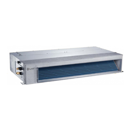
DUCT-SM 2 (for MONOsplit systems):
Series ID2-XY from 27M to 53M
DUCT-SL 2 (for LIGHT Commercial systems):
Series S.ID2+MC2-Y from 35M to 160T
Nominal cooling capacity
from 2,6 kW to 16,1 kW
R-32
INSTALLATION AND OPERATING MANUAL
Duct-SM 2
Duct-SL 2
MIDDLE STATIC PRESSURE DUCT TYPE
Change living home
Advertisement
Chapters
Table of Contents

Subscribe to Our Youtube Channel
Related Manuals for CLIVET Duct-SM 2


Summary of Contents for CLIVET Duct-SM 2
- Page 1 INSTALLATION AND OPERATING MANUAL Duct-SM 2 Duct-SL 2 MIDDLE STATIC PRESSURE DUCT TYPE DUCT-SM 2 (for MONOsplit systems): Series ID2-XY from 27M to 53M DUCT-SL 2 (for LIGHT Commercial systems): Series S.ID2+MC2-Y from 35M to 160T Nominal cooling capacity from 2,6 kW to 16,1 kW...
-
Page 2: Table Of Contents
Table of Contents Installation Manual IMPORTANT NOTE: Read this manual carefully before installing or operating your new air conditioning unit. Make sure to save this manual for future reference. Accessories ..............04 Safety Precautions ........... Installation Overview ........Indoor Unit Installation ........ - Page 3 Refrigerant Piping Connection ....... A. Notes on Pipe Length and Elevation ....24 B. Refrigerant Piping Connection Instructions ...26 Wiring .............. 28 a. Outdoor Unit Wiring ....b. Indoor Unit Wiring ....... c. Power Specifications ....Air Evacuation ............. a. Evacuation Instructions ........
-
Page 4: Accessories
Accessories The air conditioning system comes with the following accessories. Use all of the installation parts and accessories to install the air conditioner. Improper installation may result in water leakage, electrical shock and fire, or equipment failure. NAME SHAPE QUANTITY Soundproof / insulation sheath Tubing &... -
Page 5: Safety Precautions
Safety Precautions Read Safety Precautions Before Installation Incorrect installation due to ignoring instructions can cause serious damage or injury. The seriousness of potential damage or injuries is classified as either a WARNING or CAUTION. Failure to observe a warning may result in death. The appliance must be installed in accordance with national regulations. -
Page 6: Installation Overview
Installation Overview INSTALLATION ORDER Install the indoor unit Install the outdoor unit Install the drainpipe (Page 8) (Page 19) (Page 21) Evacuate the refrigeration system Connect the wires Connect the refrigerant pipes (Page 33) (Page 28 (Page 24) Perform a test run (Page 35) - Page 7 Air inlet dimensions Air filter Descending ventilation opening and mounted hook Air filter Electric control box Fig. 4.3 Table.4-1 (unit: mm/inch) Outline dimension air outlet opening size air return opening size Size of mounted lug MODEL (Btu/h) 700/27.6 200/7.9 506/19.9 450/17.7 152/6 537/21.1...
-
Page 8: Indoor Unit Installation
Indoor Unit Installation Indoor Unit Parts Air inlet Electric control cabinet Air filter(on some models) Drain hose Air outlet Refrigerant connecting pipe Fig. 4.1 Safety Precautions CAUTION WARNING • Securely install the indoor unit on a structure • Install the indoor and outdoor units, cables that can sustain its weight. - Page 9 Installation place > 11.8in(30cm) Strong and durable ceiling >0.8in(2cm) Indoor unit Right Left side side > 0.8in(2cm) Service access Ceiling >4in(10cm) >11.8in(30cm) Floor Maintenance space Air outlet (30cm) 11.8 (20cm) Air inlet 23.6 x23.6 (60cmx60cm) checking orifice Fig. 4.2 Step 2: Hang indoor unit. 1.
- Page 10 Screw nut CAUTION Shockproof cushion The unit body must be completely aligned with the hole. Ensure that the unit and the hole are Overhang part Washer the same size before moving on. Hanging screw bolt 2. Install and fit pipes and wires after you have Fig.
- Page 11 Step 4: Adjust the air inlet direction Step 5: Fresh air duct installation (From rear side to under-side.) Dimension : Duct joint for fresh air 1. Take off the ventilation panel and flange. Air return flange MODLE 53M-160M Ø125mm(4.92”) Ø160mm(6.3”) Ventilation panel Fig.
- Page 12 FAN PERFORMANCE SETTINGS N.B.: for settings with the Wired controller see pag. 30 Setting air flow Duct indoor units give the user the possibility to set a Standard Airflows profile, which the unit will keep constant adjusting itself to proper Static Pressure. The user can choose between two modes: •...
- Page 13 Air flow graphs / Static Pressure Unit 27M/35M Par.0 Par.1 Par.2 Air flow Air flow (m3 /h) (CFM) (m3 /h) (CFM) Par.3 Par.4 Air flow Air flow (m3 /h) (CFM) (m3 /h) (CFM) (Pa) = Static available pressure Fan speed High speed Medium speed Low speed...
- Page 14 Unit 153M Par.0 Par.1 Par.2 Air flow Air flow (m3 /h) (CFM) (m3 /h) (CFM) Par.3 Par.4 Air flow Air flow (m3 /h) (CFM) (m3 /h) (CFM) (Pa) = Static available pressure Fan speed High speed Medium speed Low speed...
- Page 15 Unit 70M Par.0 Par.1 Par.2 Air flow Air flow (m3 /h) (CFM) (m3 /h) (CFM) Par.3 Par.4 Air flow Air flow (m3 /h) (CFM) (m3 /h) (CFM) (Pa) = Static available pressure Fan speed High speed Medium speed Low speed...
- Page 16 Unit 105M Par.0 Par.1 Par.2 Air flow Air flow (m3 /h) (CFM) (m3 /h) (CFM) Par.3 Par.4 Air flow Air flow (m3 /h) (CFM) (m3 /h) (CFM) (Pa) = Static available pressure Fan speed High speed Medium speed Low speed...
- Page 17 Unit 140M Par.0 Par.1 Par.2 Air flow Air flow (m3 /h) (CFM) (m3 /h) (CFM) Par.3 Par.4 Air flow Air flow (m3 /h) (CFM) (m3 /h) (CFM) (Pa) = Static available pressure Fan speed High speed Medium speed Low speed...
- Page 18 Unit 160M Par.0 Par.1 Par.2 Air flow Air flow (m3 /h) (CFM) (m3 /h) (CFM) Par.3 Par.4 Air flow Air flow (m3 /h) (CFM) (m3 /h) (CFM) (Pa) = Static available pressure Fan speed High speed Medium speed Low speed...
- Page 19 Outdoor Unit Installation (LIGHT Commercial systems) The area must be free of combustible gases √ Outdoor Unit Installation Instructions and chemicals. √ The pipe length between the outdoor and Step 1: Select installation location. indoor unit may not exceed the maximum The outdoor unit should be installed in the allowable pipe length.
- Page 20 Split Type Outdoor Unit (Refer to Fig 5.4, 5.5, 5.6, 5.7 and Table 5.1) Fig. 5.4 Fig. 5.5 Fig. 5.6 Table 5.1: Length Specifications of Split Type Outdoor Unit (unit: mm/inch) Outdoor Unit Dimensions Mounting Dimensions Size Distance A Distance B W x H x D 35M/53M 800x554x333 (31.5x21.8x13.1)
- Page 21 2. Insert the drain joint into the hole in the base NOTE: The minimum distance between the pan of the unit. outdoor unit and walls described in the installation guide does not apply to airtight 3. Rotate the drain joint 90° until it clicks in place rooms.
-
Page 22: Drainpipe Installation
Drainpipe Installation The drainpipe is used to drain water away from NOTE ON DRAINPIPE INSTALLATION the unit. Improper installation may cause unit • When using an extended drainpipe, tighten and property damage. the indoor connection with an additional protection tube. This prevents it from CAUTION pulling loose. - Page 23 Units with a pump. (Accessoriys not available) 3. Using a 65-mm (2.5”) core drill, drill a hole in the wall. Make sure that the hole is drilled at 1. Remove the test cover. a slight downward angle, so that the outdoor Fill the water pan with 2 liters of water.
-
Page 24: Refrigerant Piping Connection
Refrigerant Piping Connection Safety Precautions Notes On Pipe Length and Elevation Ensure that the length of the refrigerant pipe, the number of bends, and the drop height between WARNING the indoor and outdoor units meets the • All field piping must be completed by a requirements shown in Table 7.1: licensed technician and must comply with the local and national regulations. - Page 25 CAUTION CAUTION • Oil traps If the outdoor unit is installed higher than the indoor unit: If the indoor unit is installed higher than the outdoor unit: -It is recommended that vertical suction risers not be upsized. Proper oil return to the -If oil flows back into the outdoor unit’s compressor should be maintained with suction compressor, this might cause liquid...
-
Page 26: Refrigerant Piping Connection Instructions
Table 7.2 CAUTION Permitted length DO NOT deform pipe while cutting. Be extra L+Max 24K+24K (L1, L2) careful not to damage, dent, or deform the pipe Total piping length 50/164’ 30K+30K while cutting. This will drastically reduce the heating efficiency of the unit. (farthest distance from 15/49’... - Page 27 5. Clamp flare form on the end of the pipe. NOTE: Use both a spanner and a torque wrench The end of the pipe must extend beyond when connecting or disconnecting pipes to/from the flare form. the unit. Flare form Fig.
-
Page 28: Wiring
Wiring To prevent distortion when the compressor starts Safety Precautions (you can find the unit’s power information on the rating sticker): WARNING • The unit must be connected to the main • Disconnect the power supply before outlet. Normally, the power supply must working on the unit. -
Page 29: Indoor Unit Wiring
Table 8.2: Other World Regions Indoor Unit Wiring Absorbed Nominal Cross-Sectional 1. Prepare the cable for connection. Area (mm²) maximum(A) a. Using wire strippers, strip the rubber jacket 0.75 from both ends of the signal cable to reveal about 15cm (5.9”) of the wire. 6 - 10 b. - Page 30 CAUTION While connecting the wires, please strictly • - Press “CONFIRM”. The air conditioning follow the wiring diagram. unit will then start the fan for airflow The refrigerant circuit can become very • automatic adjustment. hot. Keep the interconnection cable away from the copper tube.
-
Page 31: Power Specifications
Power Specifications NOTE: Electric auxiliary heating type circuit breaker/fuse need to add more than 10 A. Indoor Power Supply Specifications MODEL(Btu/h) 19K~24K 25K~36K 37K~48K 49K~60K PHASE 1 Phase 1 Phase 1 Phase 1 Phase 1 Phase POWER 208-240V 208-240V 208-240V 208-240V 208-240V VOLT CIRCUIT BREAKER/ 25/20... - Page 32 MODEL(Btu/h) 37K~60K 37K~60K PHASE 1 Phase 1 Phase 1 Phase 1 Phase POWER VOLT (indoor) 208-240V 208-240V 208-240V 208-240V CIRCUIT BREAKER/FUSE(A) 15/10 15/10 15/10 15/10 PHASE 3 Phase 3 Phase 3 Phase 3 Phase POWER (outdoor) VOLT 380-420V 380-420V 208-240V 208-240V CIRCUIT BREAKER/FUSE(A) 25/20...
- Page 33 Air Evacuation 4. Turn on the vacuum pump to evacuate the Safety Precautions system. 5. Run the vacuum for at least 15 minutes, or until the Compound Meter reads -76cmHG CAUTION (-1x10⁵Pa). • Use a vacuum pump with a gauge reading 6.
- Page 34 Note On Adding Refrigerant CAUTION • Refrigerant charging must be performed after wiring, vacuuming, and the leak testing. DO NOT exceed the maximum allowable quantity of refrigerant or overcharge the system. • Doing so can damage the unit or impact it’s functioning. •...
- Page 35 Test Run f. Check to see that the drainage system is Before Test Run unimpeded and draining smoothly. A test run must be performed after the entire g. Ensure there is no vibration or abnormal system has been completely installed. Confirm noise during operation.
- Page 36 European Disposal Guidelines The manufacturer is registered on the EEE National Register, in compliance with implementation of Directive 2012/19/EU and relevant national regulations on waste electrical and electronic equipment. This Directive requires electrical and electronic equipment to be disposed of properly. Equipment bearing the crossed-out wheelie bin mark must be disposed of separately at the end of its life cycle to prevent damage to human health and to the environment.
- Page 37 Information Servicing (Required for the units adopt R32/R290 Refrigerant only) 1. Checks to the area Prior to beginning work on systems containing flammable refrigerants, safety checks are necessary to ensure that the risk of ignition is minimised. For repair to the refrigerating system, the following precautions shall be complied with prior to conducting work on the system.
- Page 38 the charge size is in accordance with the room size within which the refrigerant containing parts are installed; the ventilation machinery and outlets are operating adequately and are not obstructed; if an indirect refrigerating circuit is being used, the secondary circuits shall be checked for the presence of refrigerant;...
- Page 39 11. Repair to intrinsically safe components Do not apply any permanent inductive or capacitance loads to the circuit without ensuring that this will not exceed the permissible voltage and current permitted for the equipment in use. Intrinscially safe components are the only types that can be worked on while live in the presence of a flammable atmosphere.
- Page 40 When the final OFN charge is used, the system shall be vented down to atmospheric pressure to enable work to take place. This operation is absolutely vital if brazing operations on the pipe-work are to take place. Ensure that the outlet for the vacuum pump is not closed to any ignition sources and there is ventilation available.
- Page 41 18. Labelling Equipment shall be labelled stating that it has been de-commissioned and emptied of refrigerant. The label shall be dated and signed. Ensure that there are labels on the equipment stating the equipment contains flammable refrigerant. 19. Recovery When removing refrigerant from a system, either for service or decommissioning, it is recommended good practice that all refrigerants are removed safely.
- Page 42 Technical information Technical features (MultiSplit) Outdoor unit MU1-Y 105M 125M Refrigerant lines Dual 1 2 Dual 1 2 Triple 1 3 Triple 1 3 Quadri 1 4 Quadri 1 4 Penta 1 5 Indoor units connectable (Min 2x1/4” 2x1/4” 3x1/4” 3x1/4”...
- Page 43 Technical features (Light Commercial) Outdoor unit MC2-Y 105M 105T 140T 160T Refrigerant lines 1/4” 1/4” 3/8” 3/8” 3/8” 3/8” 3/8” Liquid line 6,35 6,35 9,52 9,52 9,52 9,52 9,52 3/8” 1/2” 5/8” 5/8” 5/8” 5/8” 5/8” Gas line 9,52 12,7 15,9 15,9 15,9...
- Page 44 OWNER’S MANUAL Duct-SM 2 Duct-SL 2 MIDDLE STATIC PRESSURE DUCT TYPE AIR CONDITIONER IMPORTANT NOTE: Read this manual carefully before installing for or opera- ting your new air conditioning unit. Make sure to save this manual future reference. R-32 Change living home...
- Page 45 Table of Contents Owner’s Manual Safety Precautions ............ SAFETY FIRST Indoor Unit Parts and Major Functions ..06 Manual Operations ...........
- Page 46 Care and Maintenance ......a. Unit Maintenance ........b. How to Clean the Air Filter ....... c. Repairing Refrigerant Leaks ...... d. Preparation for Periods of Non-use ..10 Troubleshooting ......... a. Common Problems ......b. Troubleshooting Tips ......European Disposal Guidelines ..............
- Page 47 Safety Precautions Thank you for purchasing this air conditioner. This manual will provide you with information on how to operate, maintain, and troubleshoot your air conditioner. Following the instructions will ensure the proper function and extended lifespan of your unit. Please pay attention to the following signs: Failure to observe a warning may result in death.
- Page 48 DO NOT operate the air conditioner in a wet • CAUTION room (e.g. bathroom or laundry room). This DO NOT touch the air outlet while the swing • can cause electrical shock and cause the flap is in motion. Fingers might get caught product to deteriorate.
- Page 49 Indoor Unit Parts And Major Functions Unit Parts Air inlet Electric control cabinet Air filter(on some models) Air outlet Drain hose Refrigerant connecting pipe Fig. 2.1 Operating Conditions Use the system under the following temperatures for safe and effective operation. If the air conditioner is used under different conditions, it may malfunction or become less efficient.
- Page 50 Features Default Setting Louver Angle Memory Function (Optional) When the air conditioner restarts after a power Some models are designed with a louver angle failure, it will default to the factory settings memory function. When the unit restarts after a (AUTO mode, AUTO fan, 24°C (76°F)).
- Page 51 Manual Operations This display panel on the indoor unit can be used to operate the unit in case the remote control has been misplaced or is out of batteries. Manual button LED display Operation indicator Infrared receiver Alarm indicator Timer indicator PRE-DEF (pre-heating/defrost) indicator...
-
Page 52: Care And Maintenance
Care And Maintenance WARNING: DO NOT REMOVE OR Safety Precautions CLEAN THE FILTER BY YOURSELF Contact an authorized service technician for • repair or maintenance. Improper repair and Removing and cleaning the filter can be maintenance may cause water leakage, dangerous. -
Page 53: Repairing Refrigerant Leaks
Repairing Refrigerant Leaks 3. Remove the air filter. 4. Clean the air filter by vacuuming the surface or washing it in warm water with mild WARNING detergent. If the refrigerant leaks, turn off the air • A. If using a vacuum cleaner, the inlet side conditioner and any combustible heating should face the vacuum. - Page 54 Troubleshooting CAUTIONS If one of the following conditions occurs, switch off the power supply immediately and contact your dealer for further assistance. The operation light continues to flash rapidly after the unit has been restarted. • The remote control buttons do not work. •...
- Page 55 Problem Possible Causes Dust is emitted from The unit may accumulate dust during extended periods of non-use, which either the indoor or will be emitted when the unit is turned on. This can be mitigated by covering outdoor unit the unit during long periods of inactivity. The unit may absorb odors from the environment (such as furniture, cooking, The unit emits a cigarettes, etc.) which will be emitted during operations.
- Page 56 Error Codes Indoor EEPROM (Electrically Erasable Programmable Read-Only Memory) error Indoor and outdoor unit communication malfunction Indoor fan speed malfunction Indoor room temperature sensor error Evaporator coil temperature sensor error Refrigerant leak detection system malfunction Water level alarm malfunction Dual indoor unit (twin model only) communication malfunction Other twin model malfunction Overload protection...
- Page 57 European Disposal Guidelines The manufacturer is registered on the EEE National Register, in compliance with implementation of Directive 2012/19/EU and relevant national regulations on waste electrical and electronic equipment. This Directive requires electrical and electronic equipment to be disposed of properly. Equipment bearing the crossed-out wheelie bin mark must be disposed of separately at the end of its life cycle to prevent damage to human health and to the environment.
- Page 58 Connections for LIGHT Commercial...
- Page 68 BLACK Cn34 BLACK Cn55 Cn19...
- Page 70 OPTIONAL BLACK OPTIOnal GREEN WHITE Cn34 BLUE BLUE BLACK BLACK BLACK WHITE...
- Page 71 EGALE APPRESENTANTE CLIVET S.P.A. - Via Camp Lonc, 25 - Z.I. VILLAPAIERA - 32030 FELTRE (BL) – ITALIA Cap. Soc. Eur 20.000.000 i.v. – C.F. e reg.Impr. BL n°.00708410253 – R.E.A. n°.66577 –P.I./ VAT :IT 00708410253 Tel. +39 0439 3131 - Fax +39 0439 313300 – Sito Web : www.clivet.it...
- Page 72 EGALE APPRESENTANTE CLIVET S.P.A. - Via Camp Lonc, 25 - Z.I. VILLAPAIERA - 32030 FELTRE (BL) – ITALIA Cap. Soc. Eur 20.000.000 i.v. – C.F. e reg.Impr. BL n°.00708410253 – R.E.A. n°.66577 –P.I./ VAT :IT 00708410253 Tel. +39 0439 3131 - Fax +39 0439 313300 – Sito Web : www.clivet.it...
- Page 73 EGALE APPRESENTANTE CLIVET S.P.A. - Via Camp Lonc, 25 - Z.I. VILLAPAIERA - 32030 FELTRE (BL) – ITALIA Cap. Soc. Eur 20.000.000 i.v. – C.F. e reg.Impr. BL n°.00708410253 – R.E.A. n°.66577 –P.I./ VAT :IT 00708410253 Tel. +39 0439 3131 - Fax +39 0439 313300 – Sito Web : www.clivet.it...
- Page 74 EGALE APPRESENTANTE CLIVET S.P.A. - Via Camp Lonc, 25 - Z.I. VILLAPAIERA - 32030 FELTRE (BL) – ITALIA Cap. Soc. Eur 20.000.000 i.v. – C.F. e reg.Impr. BL n°.00708410253 – R.E.A. n°.66577 –P.I./ VAT :IT 00708410253 Tel. +39 0439 3131 - Fax +39 0439 313300 – Sito Web : www.clivet.it...
- Page 75 EGALE APPRESENTANTE CLIVET S.P.A. - Via Camp Lonc, 25 - Z.I. VILLAPAIERA - 32030 FELTRE (BL) – ITALIA Cap. Soc. Eur 20.000.000 i.v. – C.F. e reg.Impr. BL n°.00708410253 – R.E.A. n°.66577 –P.I./ VAT :IT 00708410253 Tel. +39 0439 3131 - Fax +39 0439 313300 – Sito Web : www.clivet.it...
- Page 76 EGALE APPRESENTANTE CLIVET S.P.A. - Via Camp Lonc, 25 - Z.I. VILLAPAIERA - 32030 FELTRE (BL) – ITALIA Cap. Soc. Eur 20.000.000 i.v. – C.F. e reg.Impr. BL n°.00708410253 – R.E.A. n°.66577 –P.I./ VAT :IT 00708410253 Tel. +39 0439 3131 - Fax +39 0439 313300 – Sito Web : www.clivet.it...
- Page 77 EGALE APPRESENTANTE CLIVET S.P.A. - Via Camp Lonc, 25 - Z.I. VILLAPAIERA - 32030 FELTRE (BL) – ITALIA Cap. Soc. Eur 20.000.000 i.v. – C.F. e reg.Impr. BL n°.00708410253 – R.E.A. n°.66577 –P.I./ VAT :IT 00708410253 Tel. +39 0439 3131 - Fax +39 0439 313300 – Sito Web : www.clivet.it...
- Page 78 EGALE APPRESENTANTE CLIVET S.P.A. - Via Camp Lonc, 25 - Z.I. VILLAPAIERA - 32030 FELTRE (BL) – ITALIA Cap. Soc. Eur 20.000.000 i.v. – C.F. e reg.Impr. BL n°.00708410253 – R.E.A. n°.66577 –P.I./ VAT :IT 00708410253 Tel. +39 0439 3131 - Fax +39 0439 313300 – Sito Web : www.clivet.it...
- Page 79 EGALE APPRESENTANTE CLIVET S.P.A. - Via Camp Lonc, 25 - Z.I. VILLAPAIERA - 32030 FELTRE (BL) – ITALIA Cap. Soc. Eur 20.000.000 i.v. – C.F. e reg.Impr. BL n°.00708410253 – R.E.A. n°.66577 –P.I./ VAT :IT 00708410253 Tel. +39 0439 3131 - Fax +39 0439 313300 – Sito Web : www.clivet.it...
- Page 80 EGALE APPRESENTANTE CLIVET S.P.A. - Via Camp Lonc, 25 - Z.I. VILLAPAIERA - 32030 FELTRE (BL) – ITALIA Cap. Soc. Eur 20.000.000 i.v. – C.F. e reg.Impr. BL n°.00708410253 – R.E.A. n°.66577 –P.I./ VAT :IT 00708410253 Tel. +39 0439 3131 - Fax +39 0439 313300 – Sito Web : www.clivet.it...
- Page 83 CLIVET GmbH (Hydronic and Applied Division) Hummelsbütteler Steindamm 84, 22851 Norderstedt - Germany Tel. + 49 (0) 40 32 59 57-0 - Fax + 49 (0) 40 32 59 57-194 - info.de@clivet.com CLIVET GmbH (VRF, Residential and Lightcom Division) Eisenstrasse 9c, 65428 Rüsselsheim/Frankfurt - Germany Tel.
Need help?
Do you have a question about the Duct-SM 2 and is the answer not in the manual?
Questions and answers