
Subscribe to Our Youtube Channel
Related Manuals for Daikin Comfort Flex CLIWP Series


Summary of Contents for Daikin Comfort Flex CLIWP Series
- Page 1 Control Manual Group: Wall Mounted Package Part Number: CLIWP CM Date: 29 May 2023 CLIWP Series Direct Expansion Unit with Scroll Compressor Model 3 RT / 5 RT Refrigerant HFC-410A 60 Hz...
- Page 2 Table of Contents Safety Warnings............3 General Description...........4 Features / Benefits............5 Control.................7 Manufactured in an ISO 9001 certified facility © 2023 Comfort Flex . Illustration and data cover the Comfort Flex product at the time of publication and we reserve the right to make changes in design and construction at any time without notice.
-
Page 3: Safety Warnings
Safety Warnings This manual provides information on the control data of the Comfort Flex CLIWP series. NOTE: Installation and maintenance should be performed only by qualified personnel who are familiar with local codes and regulations and who have experience with this type of equipment. -
Page 4: General Description
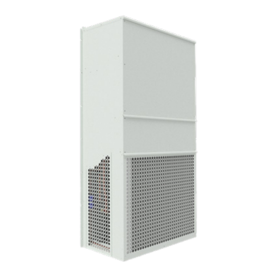
General Description Comfort Flex’s CLIWP series direct expansion Wall Attached The electrical control center includes all operating controls and Package cooling systems are complete, self-contained, automatic equipment protection necessary for reliable automatic operation. chillers designed for outdoor installation. The package units are Components housed in a weatherproof control panel. -
Page 5: Features / Benefits
Features / Benefits EFFICIENCY The control system ensures the correct operation of the equipment by monitoring in real time the condition of the major components (high or low refrigerant pressure, compressor conditions and CLIWP units are designed to meet the needs of any project for electrical power monitoring). - Page 6 Features / Benefits ElectroFin® E-Coat Coil coating corrosion resistant factory-applied ElectroFin® E-Coat is a flexible, water-based, cationic epoxy polymer using an electrodeposition coating process designed specifically for heat transfer coils in heating, air conditioning and refrigeration systems. The PPG POWERCRON® HE (high edge) technology enhances fin edge coverage through a polymerized through a unique polymer that controls the flow characteristics of the coating.
-
Page 7: Control
Control CLIWP CONTROL BY LOYTEC LIOB-585 HARDWARE INSTALLATION LIOB-585 I/O controllers are compact, IP-enabled, programmable An LIOB-58x I/O controller is connected to a BACnet network automation stations for LonMark systems and BACnet/IP networks using the Ethernet/IP port of the L-IOB device. The device must be with physical inputs and outputs and integrated graphical display. - Page 8 Control To set the BACnet device ID through the LCD display: This menu offers you, for example, the following options for the basic configuration of the device: 1. On the main LCD screen, navigate to the Device Setup “” TCP/IP configuration IP configuration page (IP address, option.
- Page 9 Control INTRODUCTION TO THE L-INX CONFIGURATOR Before setting up a working IEC61131 program, it is necessary to configure the data points of the L-IOB device. These may be I/O data points, network variables, registers, etc. Before executing the following steps, install the L-INX Configurator software from the ‘setup.exe’ file.
- Page 10 Control 2. The I/O available on that L-IOB device are shown in the Inputs / Outputs table. 3. To adapt the I/O name, double-click on the name in the Name column and edit it, e.g. ‘RoomTemp’. 4. Select (or multi-select) an I/O in the list of Inputs/Outputs and look at the list of Object Parameters below. These parameters can be used to configure the I/O.
- Page 11 Control Figure 4. Loytec Inputs / Outputs Diagram. 24 VAC TRANSFORMADOR SELECCIONADO DE ACUERDO A CONSUMO Y ALIMENTACION REQUERIDA TRANFORMADOR Neutro Linea Modbus RTU + 24VDC 120 / 220 LSTAT INSTRUMENTACION SELECCIONADA DE ACUERDO A CARACTERISTICAS DE CONTROL USE OF CLIWP SYSTEM. System startup: The CLIWP system has a digital thermostat which can be used In order to start the system, press the house icon...
- Page 12 Control LOYTEC CONTROLLER ALARMS Once the evaporator fan start time is over, the condenser fan will start and then the compressor will start, during the process of these last two steps the following icons will be displayed. The CLIWP system has 3 alarms: The first alarm is triggered by the low pressure switch and the second alarm is triggered by the high pressure switch, these alarms are digital signals which are programmed so that when an event happens where either of the...
- Page 13 Control SWITCHING FROM ONE DRIVER TO ANOTHER PROGRAMMING MODE (DISPLAY) Parameters can be changed via the front keypad. Access is different depending on the user level: support (installer) and manufacturer parameters. Modification of the Assistance parameters. Procedure The Support parameters, as well as the parameters for controller start-up, also include those for input configuration, output relay, overheating set point or control type in general and protection Press the Help and Enter keys simultaneously.
- Page 14 Control NETWORK ADDRESS - If no key is pressed, the display automatically returns to the standard display after 5 minutes. - To set a negative value, position with Enter on the leftmost The network address assigns the controller an address for serial digit and press Up/Down.
- Page 15 Control PRESSURE PROBES S1 AND S2 The superheat set point and all the parameters relative to PID control, the operation of the protectors and the meaning and use of probes S1/S3 and S2/S4 will be automatically set to the values By setting the type of pressure probe S1 for driver A and S2 for recommended by CAREL according to the selected application.
- Page 16 Control CLIWP CONTROL BY UNIVERSAL 7 DAY THERMOSTAT P722Uc FRONT PANEL CONTROLS By pressing the down key, scroll the adjustment menu to number Press enter and use the up and down keys to verify that these System heating/off/cooling mode switch: parameters are set.
- Page 17 Control NEXT button: Item #06 (Time delay): This is used when setting items such as software options and [5, default] The thermostat waits 5 minutes before turning temperature programs. the system back on after the last time it was turned on. This internal delay prevents rapid cycling and provides wallpack When items on the display are flashing during settings.
- Page 18 cm-cliwp-eng www.comfort-flex.com...
Need help?
Do you have a question about the Comfort Flex CLIWP Series and is the answer not in the manual?
Questions and answers