Chapters
Table of Contents

Subscribe to Our Youtube Channel
Related Manuals for Daikin Comfort Flex CLIV Series


Summary of Contents for Daikin Comfort Flex CLIV Series
- Page 1 Installation, Operation and Maintenance Manual Group: Chiller Part number: CLIV IOM Date: 29 May 2023 CLIV Series Air-Cooled Scroll Compressor Chilled Water Chiller Unit Model 3,5 and 10 RT Refrigerant HFC-410A 50/60 Hz...
-
Page 2: Table Of Contents
Safety Warnings............4 General Description.............5 Installation and Application Information.......................6 Refrigeration Schematics........13 Dimensions and Weights - Packaged Units....15 Refrigerant Charge...........18 Refrigerant Charge / Pressure Drop....19 Electrical Data............20 Unit Controller Operation........28 Sequence Of Operation...........32 Unit Functions............34 Circuit Functions............35 Alarms ................37 Controller Use............43 Startup and shutdown procedures....60 Unit Maintenance.............63 Troubleshooting Chart..........66... - Page 3 Pre-Start-Up Checklist - Scroll Compressor Chillers Must be completed, signed and submitted to Comfort Flex at least 2 weeks prior to the requested start date. Job name Place of installation Customer order number Model number(s) G.O. Number(s) Iniciales Chilled water and condensing water for water-cooled chillers Complete piping Water strainer(s) installed in piping according to manual requirements Water system: flushing, filling and draining;...
-
Page 4: Safety Warnings
Safety Warnings This manual contains safety instructions that must be followed during installation and maintenance of the unit. Read this manual before installing or operating this unit. NOTE: Installation and maintenance should be performed only by qualified personnel who are familiar with local codes and regulations and who have experience with this type of equipment. -
Page 5: General Description
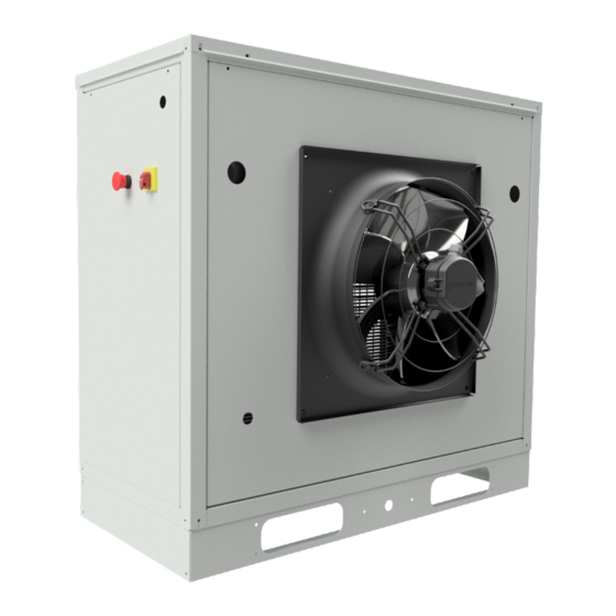
General Description Comfort Flex’s CLIV series air-cooled chilled water generators are The electrical control center includes all operating controls and complete, self-contained, automatic chillers designed for outdoor equipment protection necessary for reliable automatic operation. installation. The package units are fully assembled, factory wired, Components housed in a weatherproof control panel. -
Page 6: Installation And Application Information
Installation and Application Information Table 1. Limites De Funcionamiento Y Espera Maximum standby ambient temperature 130°F (54°C) Maximum operating ambient temperature 105°F (41°C) Minimum operating ambient temperature (standard control) 32°F(0°) Outgoing chilled water temperature 40°F A 65°F (4°C to 18°C) Outgoing chilled fluid temperatures (with antifreeze) - Note that in cases of high ambient temperature, 15°F A 65°F (-9°C to 18°C) the lowest outgoing water temperature settings may be outside the chiller operating envelope. - Page 7 Installation and Application Information PLACEMENT OF THE UNIT A. Sides The equipment must be installed in accordance with national • 4 fan models: Minimum of 1.2 m (4 ft.) and local safety standards. If no local standards are applicable, • 6 to 14 fan models: It is strongly recommended that a minimum installation must be in accordance with national standards.
- Page 8 Installation and Application Information Figure 5. Three or more units, side by side. CAUTION The performance of the unit may be affected if the operating clearance is not sufficient. Case 1. Building or wall on one side of the unit. NOTES: Assumes a solid height wall higher than the unit.
- Page 9 Installation and Application Information • Piping for units with brazed plate evaporators must have a drain and vent connection at the bottom of the bottom CAUTION connection piping and at the top of the top connection piping, respectively, see Figure 6. To prevent damage to the evaporator and possible failure of •...
- Page 10 Installation and Application Information WATER FLOW LIMITATIONS It is recommended that the field-installed water piping for the chiller include: Constant evaporator flow • Temperature sensors evaporator inlet outlet connections. Maximum flow rate and pressure drop are based on a 6°F temperature drop.
- Page 11 Installation and Application Information 2. If the chiller evaporator water temperature drops below the “freezing set point”, the chiller will attempt to start the water CAUTION pumps to prevent the evaporator from freezing. 3. If the chiller does not have the ability to start the pumps, the Improper use of detergents, chemicals and additives in the chiller will alarm for lack of water flow.
- Page 12 Installation and Application Information CONDENSER COIL OPTIONS AND COATING Considerations The standard CLIV Series chiller coils have an aluminum alloy microchannel design with a series of flat tubes containing multiple parallel flow microchannels placed between the coolant manifolds. The microchannel coils are designed to withstand the synthetic acidified seawater acidified (SWAAT) mist test of over 1000 hours (ASTM G85-02) at 120°F (49°C) with 0% loss and without developing leaks.
-
Page 13: Refrigeration Schematics
Refrigeration Schematics Figure 7. Refrigeration Schematics cooling only. www.comfort-flex.com iom-cliv-eng... - Page 14 Refrigeration Schematics Figure 8. Refrigeration Schematics heat pump. iom-cliv-eng www.comfort-flex.com...
-
Page 15: Dimensions And Weights - Packaged Units
Dimensions and Weights - Packaged Units Figure 9. Cooling only unit dimensional configuration 3-5 RT. www.comfort-flex.com iom-cliv-eng... - Page 16 Dimensions and Weights - Packaged Units Figure 10. Heat pump unit dimensional configuration 3-5 RT. iom-cliv-eng www.comfort-flex.com...
- Page 17 Dimensions and Weights - Packaged Units Figure 11. Unit dimensional configuration 10 RT ( Duplex ) www.comfort-flex.com iom-cliv-eng...
-
Page 18: Refrigerant Charge
Refrigerant Charge EMPTYING PROCEDURE WARNING Any system that has been exposed to the atmosphere must be The pump oil should be changed periodically to ensure properly dehydrated. This is achieved with a proper vacuum vacuum efficiency. procedure. To achieve a proper vacuum, a vacuum pump (not a compressor) REFRIGERANT CHARGE and a vacuometer are required. -
Page 19: Refrigerant Charge / Pressure Drop
Refrigerant Charge / Pressure Drop Table 4. Refrigerant Charge. FAMILY R410A (Lb) R410A (Kg) 3 RT 3.56 1.61 CLIV 5 RT 3.52 1.60 10 RT 3.52 1.66 Figure 12. Diagram to obtain the vacuum and for the Refrigerant Charge. Table 5. Evaporator Pressure Drop Data. EVAPORATOR DROP TOTAL DROP CAPACITY... -
Page 20: Electrical Data
Electrical Data ELECTRICAL CONNECTION CLIV units can be ordered with standard multi-point power connections or with optional single-point connections and various disconnect and circuit breaker options. Wiring inside the unit is sized in accordance with the NEC®. The required field wiring varies depending on the configuration of the unit. Voltage limitations are: 1. - Page 21 Electrical Data WARNING Stop the chiller before transferring power from the generator to the mains. Transferring power while the chiller is running can cause serious damage to the chiller. The procedure required to reconnect generator power to the grid is as follows: 1.
- Page 22 Electrical Data Figure 13. Typical field wiring diagram of the 220V unit (son) iom-cliv-eng www.comfort-flex.com...
- Page 23 Electrical Data www.comfort-flex.com iom-cliv-eng...
- Page 24 Electrical Data Figure 14. Typical field wiring diagram of 440V unit (son) iom-cliv-eng www.comfort-flex.com...
- Page 25 Electrical Data www.comfort-flex.com iom-cliv-eng...
- Page 26 Electrical Data Figure 15. Typical field wiring diagram of 220V unit (Duplex) iom-cliv-eng www.comfort-flex.com...
- Page 27 Electrical Data www.comfort-flex.com iom-cliv-eng...
-
Page 28: Unit Controller Operation
Unit Controller Operation GENERAL DESCRIPTION The CAREL “APPLICA” app, available on Google Play for the Android operating system, facilitates parameter configuration and unit commissioning operations in the field. μChiller is Carel’s solution for the complete management of chiller units, air-to-water heat pumps, water-to-water heat pumps and motor condensing units. - Page 29 Unit Controller Operation INPUTS AND OUTPUTS Tabla 6. Analog inputs Physical address Electrical diagram label Name Return Sensor Injection Sensor Condenser Sensor Tabla 7. Digital inputs Physical address Electrical diagram label Name Flow sensor Heating / cooling switch High pressure switch Low pressure switch System Cliv unit on/off switch...
- Page 30 Unit Controller Operation LOYTEC PARAMETERS SITE From this page you can change parameters which are also referenced in this manual in the CLIV unit control parameters section. Tabla de supervisión de registros modbus Variable name Holding Write Read Direction Timer_On_System_Before_Pump Timer_Flow_Detection_Pump Timer_Start_Fan Timer_Step_Compressor_on...
- Page 31 Unit Controller Operation Setpoint_cool Number_Stages Ton_Stage_2 Ton_Off_Fan Diff_Tmp Setpoint_Cold_Water Variable name Holding Write Read Direction Alarm_Indicator Switch_OnOff_Value Switch_LowPressure_Value Switch_HighPressure_Value Switch_FlowWater_Value Demand_Percent Water_Inyection_Value Water_Return_Value Status_Compressor_1 Status_Compressor_2 Status_WaterPump Status_Fan Variable name Holding Write Read Direction Reset_Alarm Switch_OnOff_Logical Switch_LowPressure_Logical Switch_HighPressure_Logical Switch_FlowWater_Logical Remote_Enabled Remote_OnOff www.comfort-flex.com iom-cliv-eng...
-
Page 32: Sequence Of Operation
Sequence Of Operation Figure 17. Sequence of operation of the unit Unit Power up Wait the time for the start up compressor Unit in OFF state The contactor auxiliar remains on while chiller is enabled Is unit enabled? Is the protection module or frecuency variator of the... - Page 33 Sequence Of Operation Operation run need more Operation of circuit in capacity?? stabilization Increase unit capacity Load is abatied? Unit turn up full capacity? Shut down the circuit. Operation of circuit in stabilization Unit turn down full capacity? Decrease unit capacity Is unit running at minimun...
-
Page 34: Unit Functions
Unit Functions CIRCUIT LOGIC CONTROL The calculations in this section are used in unit-level control logic or all-circuit control logic. Circuit enablement EVAPORATOR DELTA T A circuit must be enabled to start if the following conditions are met: The Delta T of the evaporator water is calculated as the temperature of the water entering minus that leaving through all circuits. -
Page 35: Circuit Functions
Circuit Functions CIRCUIT STATES T6 - Pre-open to Off The circuit will always be in one of four states: Any of the following is required: Off - The circuit is not running. Pre-open - The circuit is preparing to start up •... - Page 36 Circuit Functions Dimensions (Mm) Figure 19. Fan sequence according to capacity. Adjustable - ODF connections with 1/4” equalizer OVERHEATING CONTROL STATUS OPERATION TXV Operation The measurement of refrigerant flow to the evaporator is the exclusive function of a TXV. It must measure this flow at precisely Non-adjustable - Odf connections with 1/4”...
-
Page 37: Alarms
Alarms ALARMS Pressing the Alarm key silences the buzzer and displays the alarm code. Pressing UP/DOWN scrolls through the list of other possible alarms. Alarms that require technical assistance intervention indicate the request on the display by the flashing of the key icon. The lit key icon indicates that a device has reached the programmed threshold of the number of operating hours, and a maintenance intervention is required (the alarm code indicates which device is... - Page 38 Alarms Alarm Description This alarm indicates when the water return sensor or water return probe is damaged or broken. This alarm indicates when the water injection sensor is damaged or broken. This alarm indicates when there is a census or water flow problem. This alarm usually appears together with the A10 alarm as it depends on the configuration at which the pump was com- missioned, otherwise the current equipment containing this controller simply has a pump configured in this case this alarm goes together with the current pump configuration.
- Page 39 Alarms PRESENT ALARMS PARAMETER MENU After the previous step, turn the dial to the right to find parameter number 12. When an alarm occurs within the CLIV equipment the controller does not have the ability to show directly on the display the alarm that is present, however this alarm can be checked from a parameter which by means of a numeric value indicates the meaning of this alarm within this manual and within the alarm...
- Page 40 Alarms Once the above menu is selected, the network address of the device can be accessed. There are different options to which the device has to be adapted depending on the required network installation needs or remote monitoring requirements either from the device itself or a third party device such as PC’S, Tablets, or mobile devices.
- Page 41 Alarms Once the previous steps have been taken and depending on the desired selection to be able to connect the device to the needs of the network to which it is required to connect, the following options will be verified; these options are found by turning the dial to select them as shown in the following image.
- Page 42 Alarms SYSTEM ALARMS The CLIV system has an alarm section which indicates when there is a normal behavior within the equipment as shown in the following image in the part of the section where it shows no active alarms when an abnormality occurs within the equipment this legend changes to active alarms along with an alarm icon.
-
Page 43: Controller Use
Controller Use DISPLAY Status Source devices (pump Active Manual operation / fan) Compressor Manual operation (with Active status ExV) Anti-Icing Active Resistance Heating Cooling High tem. Water Mode of operation Defrosting Dripping after defrosting Legend Free cooling Keyboard Demand for Serious alarm, request exceeding the Main field... - Page 44 Controller Use SHORTCUT FUNCTIONS Only basic configuration parameters such as direct commands and active alarms can be accessed through the user terminal without password, or with password to those dedicated to unit configuration and optimization. Press DOWN for 3 s to access the direct access functions: •...
- Page 45 Controller Use Press PGR: the value flashes, press UP/DOWN PRsGolf for heat Press DOWN: the command to cancel the alarm log (ClrH) pump units, confirm. appears - Assistance level only. Press DOWN to display the heating set point (SEtH). Press DOWN: the selection of units of measurement (UoM) appears.
- Page 46 Controller Use LOYTEC CONTROLLER The status LED is intended to send a current status of the controller. This LED does not always mean that The purpose of this manual is to specify the use of the CLIV there is an error inside the controller equipment with loytec controller, then the use of the main control, but it has 2 statuses: the alarms and the operation of the equipment in general will be...
- Page 47 Controller Use Once the folder icon is selected, press the dial and you will be able to access the content of that icon and the content of the menus inside it. To access more configurations, simply repeat the above, so that you can navigate between icons or menus.
-
Page 48: Timer_On_System_Before_Pump
Controller Use Once the previous step has been performed, a menu will be accessed again and the same step of turning the dial to the right and selecting PGM1 will be repeated and pressing the dial to access the root. As you can see each menu has a number at the top of the screen, this number indicates... -
Page 49: Timer_Start_Fan
Controller Use Número de parámetro 3: Parameter number 6: Timer_Start_Fan: Timer_Stop_Compressor_By_Switch: The purpose of this parameter is to modify the fan start-up time The purpose of this parameter is to modify the time it takes for the when the system is at start-up. power button to initiate the shutdown sequence after switching off. -
Page 50: Timer_Stop_Pump
Controller Use Parameter number 9: Timer_Stop_Pump: This parameter is intended to modify the water pump shutdown time after the power off button has been activated to completely stop the system. Parameter number 12: Switch_OnOff_Logical: With this parameter you can change the N.O or N.C direction of the power switch located on the front of the panel to change the value of this parameter simply press the dial and turn the dial to the right until the active value changes or in case you want to... -
Page 51: Switch_Onoff_Value
Controller Use Parameter number 14: Parameter number 17: Switch_HighPressure_Logical: Switch_LowPressure_Value: This parameter has the purpose of changing the N.O or N.C This parameter shows the current value of the low pressure direction of the high pressure switch, to change the value of this switch input. -
Page 52: Demand_Percent
Controller Use Parameter number 20: Parameter number 23: Switch_Min_Setpoint_Cool_Value: Demand_Percent: This parameter allows changing the minimum system cooling This parameter shows the current workload capacity of the setpoint. compressor in its default is handled from zero to 100 in case the system is with a 2-stage compressor this will calculate the percentage at which the first and second compressor should turn on their due stages. -
Page 53: Water_Inyection_Value
Controller Use Parameter number 26: Parameter number 29: Ton_Off_Fan: Water_Return_Value: This parameter is used to change the fan off time during the This parameter is used to display the temperature at which the compressor operation. Return temperature sensor is registering. Parameter number 27: Parameter number 30: Diff_Temp:... -
Page 54: Remote_Enabled
Controller Use Parameter number 32: Parameter number 35: Status_Water_Pump: Remote_Enabled: This parameter is used to display the status of the water pump. The parameter allows enabling remote power-up in case an external communication with another controller is required. Parameter number 33: Parameter number 36: Status_Fan: Remote_OnOff:... - Page 55 Controller Use CONNECTION TO THE LOYECT DEVICE WHEN ASSIGNING A MANUAL ADDRESS This example will show how to make a local connection to the loytec controller in order to make a direct connection to the controller through an ethernet port. The first thing to do is to verify the address that contains the controller, this address can be seen in the main screen.
- Page 56 Controller Use From here you have to change the IP address and once this procedure is done, you will be able to open a web browser, either Firefox, Internet Explorer or another favorite search engine. Once the web browser is opened, the address containing the controller is typed in the address bar. To do this, simply observe the address of the controller on the main screen and then type it in the navigation bar as shown in the image.
- Page 57 Controller Use Once the previous step has been completed, a page with the following menus will appear in the web browser as shown in the following image. Viewing the page we access the LWEB menu. Next, it will ask again for the user: operator and password: operator.
- Page 58 Controller Use USE OF LWEB DIAGNOSTIC INTERFACE FOR CLIV EQUIPMENT The interface that contains the CLIV equipment has the objective to see more detailed temperatures and operation of the equipment in inputs and outputs. Once the previous steps have been completed, a home screen will appear with the equipment description and an access button to enter the equipment monitoring.
- Page 59 Controller Use Once the above procedure is completed, click on the open padlock icon, once this icon is clicked, the controls screen will start. Once the previous step is completed, the system status control screen can be accessed. This screen includes controls such as digital input status, digital output status and the current temperatures at which the system is working, in this case the controls here are merely representative and serve as information about the system status.
-
Page 60: Startup And Shutdown Procedures
Startup and shutdown procedures PRE-START-UP CHECKLIST The following data should be checked before putting the unit into operation. Date: Place of Work: Location: Installing Contractor: Technician/Company: Unit Commissioning: Unit model: Serial number: PHYSICAL INSPECTION (BEFORE ELECTRICAL CONNECTION) Check that the unit has not been damaged by handling or transport. Visually check for refrigerant leaks. - Page 61 Startup and shutdown procedures Check that the water filter is clean. Check that all service valves are open. Check the correct structure of the water supply. Check that all pipes are filled with water and that air has been evacuated. Check thermometers (not included from factory).
- Page 62 Startup and shutdown procedures INSPECTION OF THE CONTROL PANEL Check that the control panel is free of foreign objects. Power supply unit with three-phase electrical current. Phase unbalance should be less than 2% of average. Turn on each fan to ensure proper rotation. Turn on the water pump (if applicable) to make sure it is running.
-
Page 63: Unit Maintenance
Unit Maintenance MAINTENANCE COMPRESSOR MAINTENANCE Service or maintenance of these units should be performed The internal pressure and surface temperature of the compressor by experienced personnel with specific refrigeration training. are DANGERs and can cause permanent injury. Safety devices should be checked repeatedly and cycling control components should be analyzed and corrected before resetting Operators, installers and maintenance personnel require proper is initiated. - Page 64 Unit Maintenance FILTER DRIER WARNING Any particles from the condenser piping, compressor or various components are swept by the refrigerant into the liquid line and Risk of electric shock, can cause injury and death. trapped by the filter drier. It is recommended that the filter drier be replaced each time a Disconnect all power sources before inspecting the fan.
- Page 65 Unit Maintenance ELECTRICAL MAINTENANCE Re-tighten connectors and terminals on the Plan electrical panel, control parts, power and junction boxes (quarterly). Real Physical inspection of all electrical panel Plan connectors and relays (monthly). Real Check amperage of all electric motors, Plan compare them according to the equipment nameplate for anomalies (quarterly).
-
Page 66: Troubleshooting Chart
Troubleshooting Chart Problem Possible causes Possible corrective actions Main compressor disconnect Switch closed. switch open. Check the electrical circuit and possible short circuit, line to ground, loss of connections or motor windings causing the failure. Replace the fuse and reset Damaged fuse, open circuit brakes. - Page 67 Troubleshooting Chart Problem Possible causes Possible corrective actions Voltage unbalance or out of range. Correct power supply. Check the electrical circuit for possible problems. Then re- Faulty or grounded wiring on motor. Motor overload place the compressor. relays or circuit Loose power wiring or faulty Check all connections and tighten them, if necessary replace breakers open.
- Page 68 iom-cliv-eng www.comfort-flex.com...
Need help?
Do you have a question about the Comfort Flex CLIV Series and is the answer not in the manual?
Questions and answers