Table of Contents
Advertisement
Quick Links
Advertisement
Table of Contents
Troubleshooting

Related Manuals for Miller Swingarc SS-64M


Summary of Contents for Miller Swingarc SS-64M
- Page 1 OM-1586 155 318Z 2006−05 Processes MIG (GMAW) Welding Pulsed MIG (GMAW-P) Flux Cored (FCAW) Welding Description Wire Feeder (Use with CC/CV Power Sources) SS-64M Swingarc ™ 12 and 16 Foot File: MIG (GMAW) Visit our website at www.MillerWelds.com...
- Page 2 We know you don’t have time to do it any other way. That’s why when Niels Miller first started building arc welders in 1929, he made sure his products offered long-lasting value and superior quality.
-
Page 3: Table Of Contents
TABLE OF CONTENTS SECTION 1 − SAFETY PRECAUTIONS - READ BEFORE USING ........1-1. - Page 4 TABLE OF CONTENTS SECTION 10 − STANDARD PULSE WELDING PROGRAMS FOR PHOENIX/INVISION 456 INVERTER WELDING POWER SOURCES ..............10-1.
-
Page 5: Section 1 − Safety Precautions - Read Before Using
SECTION 1 − SAFETY PRECAUTIONS - READ BEFORE USING som _3/05 Y Warning: Protect yourself and others from injury — read and follow these precautions. 1-1. Symbol Usage Means Warning! Watch Out! There are possible hazards with this procedure! The possible hazards are shown in the adjoining symbols. - Page 6 ARC RAYS can burn eyes and skin. BUILDUP OF GAS can injure or kill. D Shut off shielding gas supply when not in use. Arc rays from the welding process produce intense visible and invisible (ultraviolet and infrared) rays D Always ventilate confined spaces or use that can burn eyes and skin.
-
Page 7: Additional Symbols For Installation, Operation, And Maintenance
D Read Owner’s Manual before using or servic- support unit. ing unit. D If using lift forks to move unit, be sure forks are D Use only genuine Miller/Hobart replacement long enough to extend beyond opposite side of parts. unit. -
Page 8: Principal Safety Standards
1-5. Principal Safety Standards Safety in Welding, Cutting, and Allied Processes, ANSI Standard Z49.1, Boulevard, Rexdale, Ontario, Canada (phone: from Global Engineering Documents (phone: 1-877-413-5184, website: 800−463−6727 or in Toronto 416−747−4044, website: www.csa−in- www.global.ihs.com). ternational.org). Practice For Occupational And Educational Eye And Face Protection, Recommended Safe Practices for the Preparation for Welding and Cut- ANSI Standard Z87.1, from American National Standards Institute, 11 ting of Containers and Piping, American Welding Society Standard... -
Page 9: Section 2 − Consignes De Sécurité − À Lire Avant Utilisation
SECTION 2 − CONSIGNES DE SÉCURITÉ − LIRE AVANT UTILISATION som _3/05 Y Avertissement : se protéger et protéger les autres contre le risque de blessure — lire et respecter ces consignes. 2-1. Symboles utilisés Symbole graphique d’avertissement ! Attention ! Cette pro- cédure comporte des risques possibles ! Les dangers éven- tuels sont représentés par les symboles graphiques joints. - Page 10 LES RAYONS D’ARC peuvent entraî- ACCUMULATIONS ner des brûlures aux yeux et à la peau. risquent de provoquer des blessures ou même la mort. Le rayonnement de l’arc du procédé de soudage génère des rayons visibles et invisibles intenses D Fermer l’alimentation du gaz protecteur en cas (ultraviolets et infrarouges) susceptibles de provo- de non-utilisation.
-
Page 11: Autres Symboles Relatifs À L'installation, Au Fonctionnement Et À L'entretien De L'appareil
D Utiliser un équipement de levage de capacité D Utiliser uniquement des pièces de rechange suffisante pour lever l’appareil. Miller/Hobart. D En utilisant des fourches de levage pour déplacer l’unité, s’assu- rer que les fourches sont suffisamment longues pour dépasser du côté... -
Page 12: Principales Normes De Sécurité
2-5. Principales normes de sécurité Safety in Welding, Cutting, and Allied Processes, ANSI Standard Z49.1, Boulevard, Rexdale, Ontario, Canada M9W 1R3 (téléphone : de Global Engineering Documents (téléphone : 1-877-413-5184, site In- 800-463-6727 ou à Toronto 416-747-4044, site Internet ternet : www.global.ihs.com). www.csa-international.org). -
Page 13: Section 3 − Introduction
SECTION 3 − INTRODUCTION 3-1. Specifications Type of Input Welding Power Wire Feed Speed Wire Diameter Welding Circuit Weight Power Source Type Range Range Rating 24 Volts AC Constant Voltage (CV) Standard: 50 To 780 ipm .023 To 1/8 in (0.6 100 Volts, 12 ft (3.7 m): Single-Phase... -
Page 14: Installing Boom And Reel Support
4-2. Installing Boom And Reel Support Swivel Plates Yoke Remove hardware from swivel plates and yoke. Boom Set boom into swivel as shown. Yoke Pin Install pin through yoke. Install cot- ter pin and spread ends. Bolt Install bolt, tighten hardware, and back bolt off one half turn. -
Page 15: Equipment Connection Diagram
4-5. Equipment Connection Diagram 300/400 Ampere Model CC/CV Inverter Welding Power Source Use settings shown for both pulse MIG welding and MIG welding. 450 Ampere Model DC Inverter Welding Power Source 14-Pin Cord Positive (+) Weld Cable Negative (−) Weld Cable Be sure weld cables are sized prop- erly for peak amperage if pulse welding (see welding power source... -
Page 16: Connecting Weld Cables And Gas Hoses
4-6. Connecting Weld Cables And Gas Hoses The weld cable and shielding gas hose extend 10 ft (3 m) from the boom. Route weld cable from boom through reed relay, if applicable. If the welding power source or gas supply are further from the boom, extend cable or hose as follows: Weld Cable Insulated Sleeving... -
Page 17: Control Box Connections
4-7. Control Box Connections Optional Reed Relay Connection Wire Feed Motor And Gas Valve Control Receptacle Wire Feed Motor And Gas Valve Control Plug From Boom 14-Pin Cord Volt Sense Lead (Optional Use) Gun Trigger Plug From Boom ST-157 433-B / Ref. ST-157 434 4-8. -
Page 18: Removing Safety Collar And Adjusting Boom
4-9. Removing Safety Collar And Adjusting Boom Locking Knob Tighten knob to prevent boom movement. Loosen knob to allow boom movement. Change knob po- sition to limit upward movement. Pull boom down slightly and remove safety collar. Boom should balance in any position from horizontal to 60 degrees above horizontal. -
Page 19: Installing And Threading Welding Wire
4-12. Installing And Threading Welding Wire Tools Needed: 15/16, 3/8 in 3/16, 5/64 in Install wire spool. Ad- just tension nut so wire is taut when wire feed stops. Pressure Indicator Scale Install wire guide. Pressure Adjust Install drive rolls. NONCONDUCTIVE NONCONDUCTIVE SURFACE... -
Page 20: Section 5 − Operation
SECTION 5 − OPERATION 5-1. Operational Terms Note See Menu Guide for detailed programming steps. The following is a list of terms and their definitions as they apply to this wire feeder: General Terms: Adaptive Pulse Welding The wire feeder automatically regulates pulse frequency to maintain a constant arc length, regardless of change in welding wire stickout. -
Page 21: Front Panel Controls
5-3. Front Panel Controls Ref. ST-155 222 Display The program number cannot be changed been struck. To end weld cycle, press and re- while welding, with exception of Dual Sched- lease gun trigger. Parameter Select Button ule Mode (see Section 7). Jog Button >... -
Page 22: Section 6 − Setting Sequence Parameters
SECTION 6 − SETTING SEQUENCE PARAMETERS 6-1. Sequence Parameters In A Program See Menu Guide for detailed programming steps. Trim is arc length. If set to zero, arc length is short. If set to 99, arc length is long. If time is set to zero in Weld sequence, welding continues until gun trigger is released. -
Page 23: Section 7 − Setting Dual Schedule Parameters
SECTION 7 − SETTING DUAL SCHEDULE PARAMETERS 7-1. Selecting Dual Schedule Pair Dual Schedule is used with two consecutive weld programs 1 & 2, 3 & 4, 5 & 6, or 7 & 8. Any program type (MIG, Adaptive Pulse, or Pulse) can be combined in dual schedule. -
Page 24: Optional Dual Schedule Switch Diagrams
7-2. Optional Dual Schedule Switch Diagrams Momen 2P (Momentary-Contact 2-Pole Switch) Maint 2P (Maintained-Contact DSS-10 DSS-9M 2-Pole Switch) Maint 1P (Maintained-Contact 1-Pole Switch) Trigger Allows dual scheduling after establishing a welding arc. Momen 1P (Momentary-Contact 1-Pole Switch) If trigger is used for dual sched- ule switch, Trigger Hold is dis- abled. -
Page 25: Section 8 − Using The Optional Data Card
SECTION 8 − USING THE OPTIONAL DATA CARD 8-1. Data Card Terms CARD SCREEN TERMS WRITE Programs To Card >W r i t e R e a d D e l e t e D o n e READ Programs From Card PULSE MIG TERMS Amperage (Pulses Per... -
Page 26: Card Displays
8-3. Card Displays See Menu Guide for detailed programming steps. Security mode only functions with a data card. Card Display Moving Line Moving line is under value that can be changed. S e q u e n c e Write D u a l S c h d Transfers program data from unit to >C a r d... -
Page 27: Entering Access Code
8-4. Entering Access Code Security Display Access code works only when a data card is inserted and Program Lock Display access mode in Setup screen is turned On. Access Code Display With a code set, this display Press appears when trying to turn off a Mode program lock. -
Page 28: Security
8-5. Security The security feature allows a mini- mum and maximum range limit to be defined for Trim, inches per min- The security feature works only when a data card is inserted. ute (IPM), and ShpArc (see Section 12). When the security lock is Off, the full range of values is available for each parameter. -
Page 29: Section 9 − System Setup
SECTION 9 − SYSTEM SETUP 9-1. Accessing The Setup Menu Setup Panel Power Switch Press and hold down both buttons while turning On unit. Main Display Main display during setup. Setup Display Follow this procedure any time access is required. Once in the setup displays, use the Mode Select button to select a particular display. -
Page 30: System Setup Display Parameters
9-2. System Setup Display Parameters Note See Menu Guide for detailed programming steps. DISPLAY SETTING NOTES >System Select the process the welding power source is able to do. >Model For the Invision 456 and XMT 304 selections, pulse data and welding power source minimum and maximum voltage values are automatically loaded in. -
Page 31: Section 10 − Standard Pulse Welding Programs
SECTION 10 − STANDARD PULSE WELDING PROGRAMS FOR PHOENIX/INVISION 456 INVERTER WELDING POWER SOURCES Note Apk = Peak Amperage, Vpk = Peak Voltage, Abk = Background Amperage, PPS = Pulses Per Second, PWms = Pulse Width (milliseconds). The following eight pulse welding programs are in the memory of the wire feeder. -
Page 32: Program 4 − Steel
10-4. Program 4 − Steel Wire Size/Type: .062” Gas: Ar - CO or Ar - Oxy / 40 CFH (19 L/m) IPM / MPM PWms COMMENTS 400 / 10.2 36.8 300 / 7.6 36.3 200 / 5.1 31.6 100 / 2.5 28.7 10-5. -
Page 33: Section 11 − Standard Pulse Welding Programs
SECTION 11 − STANDARD PULSE WELDING PROGRAMS FOR XMT 304 INVERTER WELDING POWER SOURCES Note Apk = Peak Amperage, Vpk = Peak Voltage, Abk = Background Amperage, PPS = Pulses Per Second, PWms = Pulse Width (milliseconds). The following eight pulse welding programs are in the memory of the wire feeder. -
Page 34: Program 4 − Stainless Steel
11-4. Program 4 − Stainless Steel Wire Size/Type: .030” Gas: Ar - He - CO / 40 CFH (19 L/m) IPM / MPM PWms COMMENTS 700 / 17.8 34.1 400 / 10.2 31.7 200 / 5.1 30.1 100 / 2.5 29.9 11-5. -
Page 35: Section 12 − Setting Sharparce Control
SECTION 12 − SETTING SharpArcE CONTROL 12-1. Selecting And Adjusting SharpArcE Control SharpArc™ is “Arc” on the display. It is used to adjust arc cone width and arc characteristics. Use front panel parameter select button to move > to select Arc. Use Display Control to adjust Arc setting. -
Page 36: Section 13 − Teach Points
SECTION 13 − TEACH POINTS 13-1. Teach Using 15 Points Apk = Peak Amperage Vpk = Peak Voltage Abk = Background Amperage PPS = Pulses Per Second IPM / MPM PWms = Pulse Width (Milliseconds) 780 / 19.8 750 / 19.1 700 / 17.8 650 / 16.5 600 / 15.2... -
Page 37: Redefining Teach Points
13-2. Redefining Teach Points IPM determines the weld metal de- position rate. Redefining IPM is not normally required unless special wire or unusual joint design is needed. Redefining IPM Teach Point Use front panel parameter select button to move > to select IPM. Use T r i m P r g Display Control to select teach... - Page 38 Date Program Number Wire Size/Type Wire Manufacturer Mfg. Date Flowrate CFH(L/min) Equipment Used − Power Source Serial Number Wire Feeder Serial Number Gun Model Weld Cable − Negative Positive IPM / MPM PWms COMMENTS Preflow Seconds: Run In IPM: Ramps/Start: Crater: Start Trim/Volts: IPM / MPM:...
-
Page 39: Section 14 − Maintenance And Troubleshooting
SECTION 14 − MAINTENANCE AND TROUBLESHOOTING 14-1. Routine Maintenance Y Disconnect power before maintaining. 3 Months Clean and Repair or tighten Replace replace weld unreadable cracked terminals. labels. weld cable. Replace Check Check gas Check gun cracked 14-pin cord. hose and cable. -
Page 40: Error Displays
14-3. Error Displays R e l e a s e T r i g g e r V o l t S e n s e d E r r o r Release Trigger Error Display Press front panel Parameter Select to clear error. -
Page 41: Troubleshooting
14-4. Troubleshooting Y Disconnect power before troubleshooting Trouble Remedy Wire feeds, shielding gas flows, but elec- Check interconnecting cord connections. If secure, check cord for continuity and repair or replace (see trode wire is not energized. Sections 4-5 and 4-7). Wire feeder is on, meter(s) do not light Check and reset CB1 (see Section 5-4). -
Page 42: Section 15 − Electrical Diagram
SECTION 15 − ELECTRICAL DIAGRAM Figure 15-1. Circuit Diagram OM-1586 Page 38... - Page 43 SD-183 495-B OM-1586 Page 39...
-
Page 44: Section 16 − Parts List
SECTION 16 − PARTS LIST Hardware is common and not available unless listed. 157 507-J Figure 16-1. Main Assembly OM-1586 Page 40... - Page 45 Quantity Model Item Dia. Part Mkgs. Description Figure 16-1. Main Assembly ....149 251 CABLE, trigger (consisting of) .......
- Page 46 Hardware is common and not available unless listed. ST-157 508-D Figure 16-2. Control Box OM-1586 Page 42...
- Page 47 Item Dia. Part Description Quantity Mkgs. Figure 16-2. Control Box (Fig 16-1 Item 2) ....147 139 TAPE, adh acrylic double sided .010 x .500 x 3.000 .
- Page 48 Item Dia. Part Description Quantity Mkgs. Figure 16-2. Control Box (Fig 16-1 Item 2) (Continued) ....145 948 BRACKET, mtg control box ........PC20,30 .
- Page 49 Item Part Description Quantity Figure 16-3. Support, Hub & Reel (Fig 16-1 Item 12) ... . 142 399 SUPPORT, reel ............
- Page 50 Hardware is common and not available unless listed. See Table 16-1 For Drive Roll & Wire Guide Kits ST-801 456-A Figure 16-4. Drive Assembly, Wire OM-1586 Page 46...
- Page 51 Item Dia. Part Mkgs. Description Quantity Figure 16-4. Drive Assembly, Wire (Fig 16-1 Item 25) ....010 668 SCREW, cap stl sch .250-20 x 1.500 .
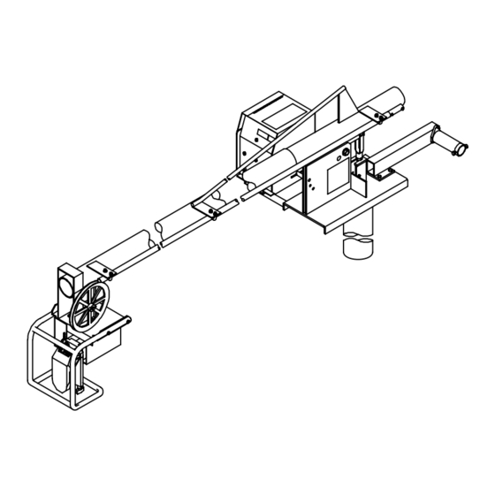
- Page 52 Hardware is common and not available unless listed. ST-142 601-F Figure 16-5. Boom Assembly OM-1586 Page 48...
- Page 53 Quantity Model Item Part Description Figure 16-5. Boom Assembly (Fig 16-1 Item 15) ..010 493 BUSHING, snap-in nyl .625 ID x .875mtg hole ......
- Page 54 Table 16-1. Drive Roll and Wire Guide Kits Wire Size V-GROOVE U-GROOVE VK-GROOVE UC-GROOVE 4 Roll 4 Roll 4 Roll 4 Roll Drive Drive Drive Drive Metric Fraction Roll Roll Roll Roll .023-.025 in. 0.6 mm 150 993 149 518 151 024 087 130 .030 in.
- Page 55 Effective January 1, 2006 (Equipment with a serial number preface of “LG” or newer) This limited warranty supersedes all previous Miller warranties and is exclusive with no other Warranty Questions? guarantees or warranties expressed or implied. LIMITED WARRANTY − Subject to the terms and conditions...
-
Page 56: Options And Accessories
Contact the Delivering Carrier to: File a claim for loss or damage during shipment. For assistance in filing or settling claims, contact your distributor and/or equipment manufacturer’s Transportation Department. © PRINTED IN USA 2006 Miller Electric Mfg. Co. 2006−01...
Need help?
Do you have a question about the Swingarc SS-64M and is the answer not in the manual?
Questions and answers