
Related Manuals for Daikin Altherma F


Summary of Contents for Daikin Altherma F
- Page 1 Installer reference guide Daikin Altherma 3 H HT F https://daikintechnicaldatahub.eu EPRA14DAV3 ETVH16SU18EA6V EPRA16DAV3 ETVH16SU23EA6V EPRA18DAV3 EPRA14DAW1 EPRA16DAW1 EPRA18DAW1...
-
Page 2: Table Of Contents
Power limitation process..........................61 6.6.4 BBR16 power limitation..........................62 Setting up an external temperature sensor ........................62 7 Unit installation Preparing the installation site............................64 Installer reference guide EPRA14~18DAV3+W1 + ETVH16SU18+23EA6V Daikin Altherma 3 H HT F 4P644738-1 – 2021.02... - Page 3 To connect the WLAN cartridge (delivered as accessory)................132 After connecting the electrical wiring to the indoor unit ....................132 10 Configuration 10.1 Overview: Configuration..............................134 EPRA14~18DAV3+W1 + ETVH16SU18+23EA6V Installer reference guide Daikin Altherma 3 H HT F 4P644738-1 – 2021.02...
- Page 4 Symptom: The system is making gurgling noises after commissioning ............248 14.3.5 Symptom: The pump is blocked........................249 14.3.6 Symptom: The pump is making noise (cavitation)..................249 Installer reference guide EPRA14~18DAV3+W1 + ETVH16SU18+23EA6V Daikin Altherma 3 H HT F 4P644738-1 – 2021.02...
- Page 5 Test results in accordance with EN12897 (2016) ..................277 16.6.2 Warning label..............................277 16.7 ESP curve: Indoor unit..............................278 17 Glossary 18 Field settings table EPRA14~18DAV3+W1 + ETVH16SU18+23EA6V Installer reference guide Daikin Altherma 3 H HT F 4P644738-1 – 2021.02...
-
Page 6: About The Documentation
Addendum book for optional equipment: Additional info about how to install optional equipment Format: Paper (in the box of the indoor unit) + Digital files on http:// www.daikineurope.com/support-and-manuals/product-information/ EPRA14~18DAV3+W1 + ETVH16SU18+23EA6V Installer reference guide Daikin Altherma 3 H HT F 4P644738-1 – 2021.02... -
Page 7: Meaning Of Warnings And Symbols
The original documentation is written in English. All other languages are translations. Technical engineering data ▪ A subset of the latest technical data is available on the regional Daikin website (publicly accessible). ▪ The full set of latest technical data is available on the Daikin Business Portal (authentication required). -
Page 8: Installer Reference Guide At A Glance
Safety instructions that you must read before installing About the documentation What documentation exists for the installer About the box How to unpack the units and remove their accessories EPRA14~18DAV3+W1 + ETVH16SU18+23EA6V Installer reference guide Daikin Altherma 3 H HT F 4P644738-1 – 2021.02... - Page 9 Note: There is also an installer settings table in the user reference guide. This table has to be filled in by the installer and handed over to the user. EPRA14~18DAV3+W1 + ETVH16SU18+23EA6V Installer reference guide Daikin Altherma 3 H HT F 4P644738-1 – 2021.02...
-
Page 10: General Safety Precautions
Improper installation or attachment of equipment or accessories could result in electrical shock, short-circuit, leaks, fire or other damage to the equipment. ONLY use accessories, optional equipment and spare parts made or approved by Daikin. WARNING Make sure installation, testing and applied materials comply with applicable legislation (on top of the instructions described in the Daikin documentation). -
Page 11: Installation Site
Make sure the field piping and connections are NOT subjected to stress. WARNING During tests, NEVER pressurise the product with a pressure higher than the maximum allowable pressure (as indicated on the nameplate of the unit). EPRA14~18DAV3+W1 + ETVH16SU18+23EA6V Installer reference guide Daikin Altherma 3 H HT F 4P644738-1 – 2021.02... - Page 12 ONLY use tools exclusively for the refrigerant type used in the system, this to ensure pressure resistance and prevent foreign materials from entering into the system. ▪ Charge the liquid refrigerant as follows: EPRA14~18DAV3+W1 + ETVH16SU18+23EA6V Installer reference guide Daikin Altherma 3 H HT F 4P644738-1 – 2021.02...
-
Page 13: Water
If NOT factory installed, a main switch or other means for disconnection, having a contact separation in all poles providing full disconnection under overvoltage category III condition, MUST be installed in the fixed wiring. EPRA14~18DAV3+W1 + ETVH16SU18+23EA6V Installer reference guide Daikin Altherma 3 H HT F 4P644738-1 – 2021.02... - Page 14 Install power cables at least 1 meter away from televisions or radios to prevent interference. Depending on the radio waves, a distance of 1 meter may NOT be sufficient. EPRA14~18DAV3+W1 + ETVH16SU18+23EA6V Installer reference guide Daikin Altherma 3 H HT F 4P644738-1 – 2021.02...
- Page 15 ON and OFF while the product is operating, attach a reversed phase protection circuit locally. Running the product in reversed phase can break the compressor and other parts. EPRA14~18DAV3+W1 + ETVH16SU18+23EA6V Installer reference guide Daikin Altherma 3 H HT F 4P644738-1 – 2021.02...
-
Page 16: Specific Installer Safety Instructions
(example: open flames, an operating gas appliance or an operating electric heater). WARNING Make sure installation, servicing, maintenance and repair comply with instructions from Daikin and with applicable legislation and are executed ONLY by authorised persons. Mounting the outdoor unit (see "7.3 Mounting the outdoor unit" [... - Page 17 WARNING Install the tundish away from any electrical device. Possible consequence: Electrical shock or fire. In case of freeze protection by glycol: EPRA14~18DAV3+W1 + ETVH16SU18+23EA6V Installer reference guide Daikin Altherma 3 H HT F 4P644738-1 – 2021.02...
- Page 18 ▪ Make electrical connections to the fixed wiring. ▪ All components procured on-site and all electrical construction MUST comply with the applicable legislation. EPRA14~18DAV3+W1 + ETVH16SU18+23EA6V Installer reference guide Daikin Altherma 3 H HT F 4P644738-1 – 2021.02...
- Page 19 This maximum allowable hot water temperature shall be selected according to the applicable legislation. EPRA14~18DAV3+W1 + ETVH16SU18+23EA6V Installer reference guide Daikin Altherma 3 H HT F 4P644738-1 – 2021.02...
- Page 20 Check the condition of the O-rings and replace if needed. Apply water to the O-rings before installation. CAUTION Make sure to open the valve (if equipped) towards the expansion vessel, otherwise the overpressure will be generated. EPRA14~18DAV3+W1 + ETVH16SU18+23EA6V Installer reference guide Daikin Altherma 3 H HT F 4P644738-1 – 2021.02...
- Page 21 If yes, make sure that the room where you want to purge air is sufficiently ventilated. Reason: Refrigerant might leak into the water circuit, and subsequently into the room when you purge air from the heat emitters or collectors. EPRA14~18DAV3+W1 + ETVH16SU18+23EA6V Installer reference guide Daikin Altherma 3 H HT F 4P644738-1 – 2021.02...
-
Page 22: About The Box
To avoid injury, do NOT touch the air inlet or aluminium fins of the unit. Crane Keep the slings within the marked area to not damage the unit. EPRA14~18DAV3+W1 + ETVH16SU18+23EA6V Installer reference guide Daikin Altherma 3 H HT F 4P644738-1 – 2021.02... - Page 23 After unpacking, carry the unit using the slings attached to the unit. See also: ▪ "4.2.2 To unpack the outdoor unit" [ 24] ▪ "7.3.4 To install the outdoor unit" [ 74] EPRA14~18DAV3+W1 + ETVH16SU18+23EA6V Installer reference guide Daikin Altherma 3 H HT F 4P644738-1 – 2021.02...
-
Page 24: To Unpack The Outdoor Unit
About the box ±150 4× 4.2.2 To unpack the outdoor unit EPRA14~18DAV3+W1 + ETVH16SU18+23EA6V Installer reference guide Daikin Altherma 3 H HT F 4P644738-1 – 2021.02... -
Page 25: To Remove The Accessories From The Outdoor Unit
Bring the packed unit as close as possible to its final installation position to prevent damage during transport. ▪ Unpack the indoor unit completely according to the instructions mentioned on the unpacking instructions sheet. EPRA14~18DAV3+W1 + ETVH16SU18+23EA6V Installer reference guide Daikin Altherma 3 H HT F 4P644738-1 – 2021.02... -
Page 26: To Unpack The Indoor Unit
Sealing tape for low voltage wiring intake 4.3.3 To handle the indoor unit Use the handles at the back and at the bottom to carry the unit. EPRA14~18DAV3+W1 + ETVH16SU18+23EA6V Installer reference guide Daikin Altherma 3 H HT F 4P644738-1 – 2021.02... -
Page 27: Domestic Hot Water Tank Kit
For installation compliant with section G3 of the Building Regulations, you must verify that the following accessories are present. Delivered with indoor unit: Tundish 15 mm inlet, 22 mm outlet EPRA14~18DAV3+W1 + ETVH16SU18+23EA6V Installer reference guide Daikin Altherma 3 H HT F 4P644738-1 – 2021.02... - Page 28 Adaptor 22 mm×3/4" Female BSP T-piece 22 mm×22 mm×22 mm Tundish 15 mm inlet, 22 mm outlet Wall mounting set for expansion vessel Instruction sheet Expansion vessel of 18 l – 3/4" Male BSP EPRA14~18DAV3+W1 + ETVH16SU18+23EA6V Installer reference guide Daikin Altherma 3 H HT F 4P644738-1 – 2021.02...
-
Page 29: About The Units And Options
Explanation European hydro-split outdoor pair heat pump High water temperature – ambient zone 2 (see operation range) Refrigerant R32 Capacity class Model series Power supply EPRA14~18DAV3+W1 + ETVH16SU18+23EA6V Installer reference guide Daikin Altherma 3 H HT F 4P644738-1 – 2021.02... -
Page 30: Identification Label: Indoor Unit
EKMST2 with rubber feet: to install the outdoor unit on foundations where drilling is not allowed or possible, such as flat roofs or pavements. For installation instructions, see the installation manual of the mounting stand. EPRA14~18DAV3+W1 + ETVH16SU18+23EA6V Installer reference guide Daikin Altherma 3 H HT F 4P644738-1 – 2021.02... -
Page 31: Possible Options For The Indoor Unit
As an option the remote indoor sensor can be installed to measure the room temperature on another location. For installation instructions, see the installation manual of the remote indoor sensor and addendum book for optional equipment. EPRA14~18DAV3+W1 + ETVH16SU18+23EA6V Installer reference guide Daikin Altherma 3 H HT F 4P644738-1 – 2021.02... - Page 32 Bizone kit (EKMIKPOA or EKMIKPHA) You can install an optional bizone kit. For installation instructions, see the installation manual of the bizone kit. See also: EPRA14~18DAV3+W1 + ETVH16SU18+23EA6V Installer reference guide Daikin Altherma 3 H HT F 4P644738-1 – 2021.02...
- Page 33 The installation of the optional Smart grid relay kit is required in case of high voltage Smart grid contacts (EKRELSG). For installation instructions, see "9.3.11 To connect a Smart Grid" [ 128]. EPRA14~18DAV3+W1 + ETVH16SU18+23EA6V Installer reference guide Daikin Altherma 3 H HT F 4P644738-1 – 2021.02...
-
Page 34: Application Guidelines
Setting up the domestic hot water tank ▪ Setting up the energy metering ▪ Setting up the power consumption control ▪ Setting up an external temperature sensor EPRA14~18DAV3+W1 + ETVH16SU18+23EA6V Installer reference guide Daikin Altherma 3 H HT F 4P644738-1 – 2021.02... -
Page 35: Setting Up The Space Heating/Cooling System
Automatic. NOTICE An overpressure bypass valve can be integrated in the system. Keep in mind that this valve might not be shown on the illustrations. EPRA14~18DAV3+W1 + ETVH16SU18+23EA6V Installer reference guide Daikin Altherma 3 H HT F 4P644738-1 – 2021.02... -
Page 36: Single Room
For your daily needs, you can use preset values and schedules. To deviate from your daily needs, you can temporarily overrule the preset values and schedules, or use the holiday mode. EPRA14~18DAV3+W1 + ETVH16SU18+23EA6V Installer reference guide Daikin Altherma 3 H HT F 4P644738-1 – 2021.02... - Page 37 Code: [C-05] heating or cooling demand. Benefits ▪ Wireless. The Daikin external room thermostat is available in a wireless version. ▪ Efficiency. Although the external room thermostat only sends ON/OFF signals, it is specifically designed for the heat pump system. ▪...
- Page 38 OFF condition. No separation between ▪ Code: [C-05] heating or cooling demand. Benefits ▪ Cooling. The heat pump convector offers, besides heating capacity, also excellent cooling capacity. EPRA14~18DAV3+W1 + ETVH16SU18+23EA6V Installer reference guide Daikin Altherma 3 H HT F 4P644738-1 – 2021.02...
- Page 39 ▪ The space operation mode is sent by one digital output (X2M/4 and X2M/3) on the indoor unit to: The heat pump convectors The shut-off valve EPRA14~18DAV3+W1 + ETVH16SU18+23EA6V Installer reference guide Daikin Altherma 3 H HT F 4P644738-1 – 2021.02...
-
Page 40: Multiple Rooms - One Lwt Zone
Human Comfort Interface (BRC1HHDA) or an external room thermostat), while the other rooms are controlled by so-called thermostatic valves, which open or close depending on the room temperature. Setup EPRA14~18DAV3+W1 + ETVH16SU18+23EA6V Installer reference guide Daikin Altherma 3 H HT F 4P644738-1 – 2021.02... - Page 41 ▪ For more information about connecting the electrical wiring to the unit, see: "9.2 Connections to the outdoor unit" [ 105] "9.3 Connections to the indoor unit" [ 112] EPRA14~18DAV3+W1 + ETVH16SU18+23EA6V Installer reference guide Daikin Altherma 3 H HT F 4P644738-1 – 2021.02...
- Page 42 ▪ For more information about connecting the electrical wiring to the unit, see: "9.2 Connections to the outdoor unit" [ 105] "9.3 Connections to the indoor unit" [ 112] EPRA14~18DAV3+W1 + ETVH16SU18+23EA6V Installer reference guide Daikin Altherma 3 H HT F 4P644738-1 – 2021.02...
- Page 43 Combination: Underfloor heating + Heat pump convectors – Multiple rooms Setup A Main leaving water temperature zone B Room 1 C Room 2 a External room thermostat b Heat pump convectors (+ controllers) EPRA14~18DAV3+W1 + ETVH16SU18+23EA6V Installer reference guide Daikin Altherma 3 H HT F 4P644738-1 – 2021.02...
-
Page 44: Multiple Rooms - Two Lwt Zones
Main zone = Zone with the lowest design temperature in heating, and the highest design temperature in cooling ▪ Additional zone = Zone with the highest design temperature in heating, and the lowest design temperature in cooling EPRA14~18DAV3+W1 + ETVH16SU18+23EA6V Installer reference guide Daikin Altherma 3 H HT F 4P644738-1 – 2021.02... - Page 45 (no real cooling), or NOT allow it. See setup below. Setup Three bizone kit system variations are possible: System without hydraulic separator: System with hydraulic separator for main zone: EPRA14~18DAV3+W1 + ETVH16SU18+23EA6V Installer reference guide Daikin Altherma 3 H HT F 4P644738-1 – 2021.02...
- Page 46 This is to guarantee the correct water flow balance between the main leaving water temperature zone and the additional leaving water temperature zone in relation to the required capacity of both water temperature zones. EPRA14~18DAV3+W1 + ETVH16SU18+23EA6V Installer reference guide Daikin Altherma 3 H HT F 4P644738-1 – 2021.02...
- Page 47 The user interface integrated in the indoor unit decides the space operation mode. Mind that the operation mode on each controller of the heat pump convectors must be set to match the indoor unit. EPRA14~18DAV3+W1 + ETVH16SU18+23EA6V Installer reference guide Daikin Altherma 3 H HT F 4P644738-1 – 2021.02...
- Page 48 The combination of the two heat emitter systems provides the excellent heating comfort of the underfloor heating, and the excellent cooling comfort of the heat pump convectors. EPRA14~18DAV3+W1 + ETVH16SU18+23EA6V Installer reference guide Daikin Altherma 3 H HT F 4P644738-1 – 2021.02...
-
Page 49: Setting Up An Auxiliary Heat Source For Space Heating
During heating operation of the auxiliary boiler, the auxiliary boiler operates to achieve the desired water temperature set via the auxiliary boiler controller. Setup ▪ Integrate the auxiliary boiler as follows: EPRA14~18DAV3+W1 + ETVH16SU18+23EA6V Installer reference guide Daikin Altherma 3 H HT F 4P644738-1 – 2021.02... - Page 50 Make sure the auxiliary boiler and its integration in the system complies with applicable legislation. ▪ Daikin is NOT responsible for incorrect or unsafe situations in the auxiliary boiler system. ▪ Make sure the return water to the heat pump does NOT exceed 60°C. To do so: Set the desired water temperature via the auxiliary boiler controller to maximum 60°C.
- Page 51 To prevent freeze-up of the water piping, the auxiliary gas boiler must have a fixed setpoint ≥55°C, or a weather-dependent setpoint ≥T (°C) –30 –25 –20 –15 –10 –5 (°C) Outdoor temperature Minimum weather-dependent setpoint for auxiliary gas boiler EPRA14~18DAV3+W1 + ETVH16SU18+23EA6V Installer reference guide Daikin Altherma 3 H HT F 4P644738-1 – 2021.02...
-
Page 52: Setting Up The Domestic Hot Water Tank
Example: If the DHW consumption of a family (4 persons) per day is as follows: ▪ 3 showers ▪ 1 bath ▪ 3 sink volumes Then the DHW consumption = (3×100 l)+(1×150 l)+(3×10 l)=480 l EPRA14~18DAV3+W1 + ETVH16SU18+23EA6V Installer reference guide Daikin Altherma 3 H HT F 4P644738-1 – 2021.02... -
Page 53: Setup And Configuration - Dhw Tank
6.4.3 Setup and configuration – DHW tank ▪ For large DHW consumptions, you can heat up the DHW tank several times during the day. EPRA14~18DAV3+W1 + ETVH16SU18+23EA6V Installer reference guide Daikin Altherma 3 H HT F 4P644738-1 – 2021.02... -
Page 54: Dhw Pump For Instant Hot Water
You can program a schedule to control the DHW pump via the user interface. For more information, see the user reference guide. 6.4.5 DHW pump for disinfection Setup EPRA14~18DAV3+W1 + ETVH16SU18+23EA6V Installer reference guide Daikin Altherma 3 H HT F 4P644738-1 – 2021.02... -
Page 55: Setting Up The Energy Metering
▪ The produced heat is calculated internally based on: The leaving and entering water temperature The flow rate EPRA14~18DAV3+W1 + ETVH16SU18+23EA6V Installer reference guide Daikin Altherma 3 H HT F 4P644738-1 – 2021.02... -
Page 56: Consumed Energy
Backup heater supplied from a single- (*3V, *6V (6V): 1N~ 230 V) phase grid (i.e. the backup heater model is *3V or *6V connected to a single-phase grid) EPRA14~18DAV3+W1 + ETVH16SU18+23EA6V Installer reference guide Daikin Altherma 3 H HT F 4P644738-1 – 2021.02... - Page 57 NOT have to set which meter covers which power consumption. You only need to set the number of pulses of each power meter. ▪ "6.5.4 Preferential kWh rate power supply" [ 58] for an example with two power meters. EPRA14~18DAV3+W1 + ETVH16SU18+23EA6V Installer reference guide Daikin Altherma 3 H HT F 4P644738-1 – 2021.02...
-
Page 58: Preferential Kwh Rate Power Supply
6.6 Setting up the power consumption control You can use the following power consumption controls. For more information about the corresponding settings, see "Power consumption control" [ 207]. EPRA14~18DAV3+W1 + ETVH16SU18+23EA6V Installer reference guide Daikin Altherma 3 H HT F 4P644738-1 – 2021.02... -
Page 59: Permanent Power Limitation
DHW production. Power input t Time DI Digital input (power limitation level) a Power limitation active b Actual power input EPRA14~18DAV3+W1 + ETVH16SU18+23EA6V Installer reference guide Daikin Altherma 3 H HT F 4P644738-1 – 2021.02... -
Page 60: Power Limitation Activated By Digital Inputs
6.6.2 Power limitation activated by digital inputs Power limitation is also useful in combination with an energy management system. The power or current of the entire Daikin system is limited dynamically by digital inputs (maximum four steps). Each power limitation level is set via the user interface by limiting one of the following: ▪... -
Page 61: Power Limitation Process
Produced heat Consumed energy A Outdoor unit B Backup heater a Limited outdoor unit operation b Full outdoor unit operation c Backup heater step 1 turned ON EPRA14~18DAV3+W1 + ETVH16SU18+23EA6V Installer reference guide Daikin Altherma 3 H HT F 4P644738-1 – 2021.02... -
Page 62: Bbr16 Power Limitation
You can connect one external temperature sensor. It measures the indoor or outdoor ambient temperature. We recommend to use an external temperature sensor in the following cases: EPRA14~18DAV3+W1 + ETVH16SU18+23EA6V Installer reference guide Daikin Altherma 3 H HT F 4P644738-1 – 2021.02... - Page 63 To protect the outdoor unit, the internal sensor of the outdoor unit is always used. EPRA14~18DAV3+W1 + ETVH16SU18+23EA6V Installer reference guide Daikin Altherma 3 H HT F 4P644738-1 – 2021.02...
-
Page 64: Unit Installation
Mind the spacing guidelines. See "16.1 Service space: Outdoor unit" [ 263]. NOTICE ▪ Do NOT stack the units on each other. ▪ Do NOT hang the unit on a ceiling. EPRA14~18DAV3+W1 + ETVH16SU18+23EA6V Installer reference guide Daikin Altherma 3 H HT F 4P644738-1 – 2021.02... - Page 65 This is to prevent corrosion caused by high levels of salt in the air, which might shorten the life of the unit. Install the outdoor unit away from direct sea winds. Example: Behind the building. EPRA14~18DAV3+W1 + ETVH16SU18+23EA6V Installer reference guide Daikin Altherma 3 H HT F 4P644738-1 – 2021.02...
- Page 66 WARNING Make sure installation, servicing, maintenance and repair comply with instructions from Daikin and with applicable legislation and are executed ONLY by authorised persons. EPRA14~18DAV3+W1 + ETVH16SU18+23EA6V Installer reference guide Daikin Altherma 3 H HT F 4P644738-1 –...
-
Page 67: Additional Installation Site Requirements Of The Outdoor Unit In Cold Climates
Heating only models + conversion kit (EKHVCONV*) ▪ Mind the measurement guidelines: Maximum height difference between indoor unit and outdoor 10 m unit Maximum total water piping length 50 m EPRA14~18DAV3+W1 + ETVH16SU18+23EA6V Installer reference guide Daikin Altherma 3 H HT F 4P644738-1 – 2021.02... -
Page 68: Opening And Closing The Units
Precise water piping length can be determined using the Hydronic Piping Calculation tool. The Hydronic Piping Calculation tool is part of the Heating Solutions Navigator which can be reached via https://professional.standbyme.daikin.eu. Please contact your dealer if you have no access to Heating Solutions Navigator. -
Page 69: To Remove The Transportation Stay
3 Remove the transportation stays (2×), and dispose of them. 7.2.4 To close the outdoor unit NOTICE When closing the outdoor unit cover, make sure that the tightening torque does NOT exceed 4.1 N•m. EPRA14~18DAV3+W1 + ETVH16SU18+23EA6V Installer reference guide Daikin Altherma 3 H HT F 4P644738-1 – 2021.02... -
Page 70: To Open The Indoor Unit
NOTICE If you remove the user interface panel, also disconnect the cables from the back of the user interface panel to prevent damage. EPRA14~18DAV3+W1 + ETVH16SU18+23EA6V Installer reference guide Daikin Altherma 3 H HT F 4P644738-1 – 2021.02... - Page 71 ▪ When you need access to the high voltage switch box 2× 5 If you need access to the high voltage components, remove the high voltage switch box cover. EPRA14~18DAV3+W1 + ETVH16SU18+23EA6V Installer reference guide Daikin Altherma 3 H HT F 4P644738-1 – 2021.02...
-
Page 72: To Lower The Switch Box On The Indoor Unit
2 Tilt the switch box to the front and lift it out of its hinges. 2× 3 Place the switch box lower on the unit. Use the 2 hinges located lower on the unit. EPRA14~18DAV3+W1 + ETVH16SU18+23EA6V Installer reference guide Daikin Altherma 3 H HT F 4P644738-1 – 2021.02... -
Page 73: To Close The Indoor Unit
Check the strength and level of the installation ground so that the unit will not cause any operating vibration or noise. Fix the unit securely by means of foundation bolts in accordance with the foundation drawing. EPRA14~18DAV3+W1 + ETVH16SU18+23EA6V Installer reference guide Daikin Altherma 3 H HT F 4P644738-1 – 2021.02... -
Page 74: To Install The Outdoor Unit
Make sure not to cover the drain hole in the bottom plate of the unit. 7.3.4 To install the outdoor unit 1 Carry the unit by its slings, and put it onto the installation structure. EPRA14~18DAV3+W1 + ETVH16SU18+23EA6V Installer reference guide Daikin Altherma 3 H HT F 4P644738-1 – 2021.02... -
Page 75: To Provide Drainage
Install the unit on a base to make sure that there is proper drainage in order to avoid ice accumulation. ▪ Prepare a water drainage channel around the foundation to drain waste water away from the unit. EPRA14~18DAV3+W1 + ETVH16SU18+23EA6V Installer reference guide Daikin Altherma 3 H HT F 4P644738-1 – 2021.02... - Page 76 O-ring (delivered as accessory) c Drain plug (delivered as accessory) d Hose (field supply) NOTICE O-ring. Make sure the O-ring is installed correctly to prevent leakage. EPRA14~18DAV3+W1 + ETVH16SU18+23EA6V Installer reference guide Daikin Altherma 3 H HT F 4P644738-1 – 2021.02...
-
Page 77: To Install The Discharge Grille
4 Align and attach the left side. 5 Align and attach the middle part. 6 Align and attach the right side. EPRA14~18DAV3+W1 + ETVH16SU18+23EA6V Installer reference guide Daikin Altherma 3 H HT F 4P644738-1 – 2021.02... -
Page 78: To Remove The Discharge Grille, And Put The Grille In Safety Position
77] ▪ "7.3.7 To remove the discharge grille, and put the grille in safety position" [ 78] 1 Remove the upper part of the discharge grille. EPRA14~18DAV3+W1 + ETVH16SU18+23EA6V Installer reference guide Daikin Altherma 3 H HT F 4P644738-1 – 2021.02... - Page 79 4 Align the ball stud and hook on the grille with their counterparts on the unit. 5 Insert the hook. 6 Insert the ball stud. EPRA14~18DAV3+W1 + ETVH16SU18+23EA6V Installer reference guide Daikin Altherma 3 H HT F 4P644738-1 – 2021.02...
-
Page 80: Mounting The Indoor Unit
3 Slide the indoor unit into position. 4 Adjust the height of the leveling feet to compensate for floor irregularities. The maximum allowed deviation is 1°. ≤1° EPRA14~18DAV3+W1 + ETVH16SU18+23EA6V Installer reference guide Daikin Altherma 3 H HT F 4P644738-1 – 2021.02... -
Page 81: To Connect The Drain Hose To The Drain
4 Reattach the side panel. Ensure the water can flow through the drain tube. It is recommended to use a tundish to collect the water. Option 1: Through the left side panel 3× EPRA14~18DAV3+W1 + ETVH16SU18+23EA6V Installer reference guide Daikin Altherma 3 H HT F 4P644738-1 – 2021.02... - Page 82 Unit installation Option 2: Through the right side panel 3× EPRA14~18DAV3+W1 + ETVH16SU18+23EA6V Installer reference guide Daikin Altherma 3 H HT F 4P644738-1 – 2021.02...
-
Page 83: Piping Installation
Because brass is a soft material, use appropriate tooling for connecting the water circuit. Inappropriate tooling will cause damage to the pipes. ▪ Insulation. Insulate up to the base of the heat exchanger. EPRA14~18DAV3+W1 + ETVH16SU18+23EA6V Installer reference guide Daikin Altherma 3 H HT F 4P644738-1 – 2021.02... - Page 84 The following illustration is an example and might NOT match your system layout. 89°C (*) 75°C (*) 75°C (*) (*) Maximum temperature for piping and accessories EPRA14~18DAV3+W1 + ETVH16SU18+23EA6V Installer reference guide Daikin Altherma 3 H HT F 4P644738-1 – 2021.02...
- Page 85 Domestic hot water tank – Standstills. In cases where during longer periods of time there is no consumption of hot water, the equipment MUST be flushed with fresh water before usage. EPRA14~18DAV3+W1 + ETVH16SU18+23EA6V Installer reference guide Daikin Altherma 3 H HT F 4P644738-1 – 2021.02...
- Page 86 Recirculation connection b Hot water connection c Shower d Recirculation pump EPRA14~18DAV3+W1 + ETVH16SU18+23EA6V Installer reference guide Daikin Altherma 3 H HT F 4P644738-1 – 2021.02...
-
Page 87: Formula To Calculate The Expansion Vessel Pre-Pressure
For more information on the addition of glycol, refer to "8.2.7 To protect the water circuit against freezing" [ 97]. Use the following graph to determine the maximum water volume for the calculated pre-pressure. EPRA14~18DAV3+W1 + ETVH16SU18+23EA6V Installer reference guide Daikin Altherma 3 H HT F 4P644738-1 – 2021.02... - Page 88 This minimum flow rate is required during defrost/backup heater operation. For this purpose, use the overpressure bypass valve delivered with the unit, and respect the minimum water volume. Minimum required flow rate 25 l/min EPRA14~18DAV3+W1 + ETVH16SU18+23EA6V Installer reference guide Daikin Altherma 3 H HT F 4P644738-1 – 2021.02...
-
Page 89: Changing The Pre-Pressure Of The Expansion Vessel
Changing the pre-pressure of the expansion vessel should be done by releasing or increasing nitrogen pressure through the Schrader valve of the expansion vessel. a Schrader valve EPRA14~18DAV3+W1 + ETVH16SU18+23EA6V Installer reference guide Daikin Altherma 3 H HT F 4P644738-1 – 2021.02... -
Page 90: To Check The Water Volume: Examples
8.2.2 Precautions when connecting the water piping INFORMATION Also read the precautions and requirements in the following chapters: ▪ "2 General safety precautions" [ 10] ▪ "8.1 Preparing water piping" [ 83] EPRA14~18DAV3+W1 + ETVH16SU18+23EA6V Installer reference guide Daikin Altherma 3 H HT F 4P644738-1 – 2021.02... -
Page 91: To Connect The Water Piping
3 Connect the O-rings and shut-off valves to the space heating/cooling water pipes of the indoor unit. 4 Connect the space heating/cooling field piping of both zones to the shut-off valves. EPRA14~18DAV3+W1 + ETVH16SU18+23EA6V Installer reference guide Daikin Altherma 3 H HT F 4P644738-1 – 2021.02... - Page 92 A pressure relief valve (field supply) with an opening pressure of maximum 10 bar (=1 MPa) must be installed on the domestic cold water inlet connection in accordance with the applicable legislation. EPRA14~18DAV3+W1 + ETVH16SU18+23EA6V Installer reference guide Daikin Altherma 3 H HT F 4P644738-1 – 2021.02...
-
Page 93: To Connect The Water Piping For Domestic Hot Water
Pressure reducing valve/pressure relief valve combination. Water inlet and water outlet 22 mm connection, discharge piping connection 15 mm b Adaptor 22 mm×3/4" Female BSP c T-piece 22 mm×22 mm×22 mm EPRA14~18DAV3+W1 + ETVH16SU18+23EA6V Installer reference guide Daikin Altherma 3 H HT F 4P644738-1 – 2021.02... - Page 94 26]) to the pipe connection located at the back of the unit. This pipe starts at the pressure relief valve of the domestic hot water tank. EPRA14~18DAV3+W1 + ETVH16SU18+23EA6V Installer reference guide Daikin Altherma 3 H HT F 4P644738-1 – 2021.02...
- Page 95 ▪ The discharge pipe away from the tundish must terminate in a safe, visible position without forming any risk to persons in the vicinity. EPRA14~18DAV3+W1 + ETVH16SU18+23EA6V Installer reference guide Daikin Altherma 3 H HT F 4P644738-1 – 2021.02...
-
Page 96: To Connect The Recirculation Piping
Make sure both air purge valves (one on the magnetic filter and one on the backup heater) are open. All automatic air purge valves MUST remain open after commissioning. EPRA14~18DAV3+W1 + ETVH16SU18+23EA6V Installer reference guide Daikin Altherma 3 H HT F 4P644738-1 – 2021.02... -
Page 97: To Protect The Water Circuit Against Freezing
As a result, the hydraulic components might freeze up after all. Take preventive actions to ensure a minimal exposure of the glycol to air. EPRA14~18DAV3+W1 + ETVH16SU18+23EA6V Installer reference guide Daikin Altherma 3 H HT F 4P644738-1 – 2021.02... - Page 98 Glycol and the maximum allowed water volume Adding glycol to the water circuit reduces the maximum allowed water volume of the system. For more information, see "Maximum water volume" [ 87]. EPRA14~18DAV3+W1 + ETVH16SU18+23EA6V Installer reference guide Daikin Altherma 3 H HT F 4P644738-1 – 2021.02...
- Page 99 In other circumstances (example: when there is a pump failure): The normally closed valves remain open. If the freeze protection valves open, the water from inside the house is also drained. EPRA14~18DAV3+W1 + ETVH16SU18+23EA6V Installer reference guide Daikin Altherma 3 H HT F 4P644738-1 – 2021.02...
-
Page 100: To Fill The Domestic Hot Water Tank
The Hydronic Piping Calculation tool is part of the Heating Solutions Navigator which can be reached via https://professional.standbyme.daikin.eu. Please contact your dealer if you have no access to Heating Solutions Navigator. This recommendation ensures good operation of the unit, however, local regulations may differ and shall be followed. -
Page 101: Electrical Installation
DANGER: RISK OF ELECTROCUTION WARNING ALWAYS use multicore cable for power supply cables. INFORMATION Also read the precautions and requirements in the "2 General safety precautions" [ 10]. EPRA14~18DAV3+W1 + ETVH16SU18+23EA6V Installer reference guide Daikin Altherma 3 H HT F 4P644738-1 – 2021.02... -
Page 102: Guidelines When Connecting The Electrical Wiring
Stranded conductor wire b Round crimp-style terminal ▪ Use the following methods for installing wires: EPRA14~18DAV3+W1 + ETVH16SU18+23EA6V Installer reference guide Daikin Altherma 3 H HT F 4P644738-1 – 2021.02... -
Page 103: About Electrical Compliance
Equipment complying with EN/IEC 61000‑3‑12 (European/International Technical Standard setting the limits for harmonic currents produced by equipment connected to public low-voltage systems with input current >16 A and ≤75 A per phase.). EPRA14~18DAV3+W1 + ETVH16SU18+23EA6V Installer reference guide Daikin Altherma 3 H HT F 4P644738-1 – 2021.02... -
Page 104: About Preferential Kwh Rate Power Supply
5 Normal kWh rate power supply (to power the indoor unit PCB in the event of power supply interruption of the preferential kWh rate power supply) EPRA14~18DAV3+W1 + ETVH16SU18+23EA6V Installer reference guide Daikin Altherma 3 H HT F 4P644738-1 – 2021.02... -
Page 105: Connections To The Outdoor Unit
(optional) Drain tube heater cable (field supply) d Cable sleeves (factory-mounted) 4 Inside the switch box, connect the wires to the appropriate terminals, and fix the cables with cable ties. See: EPRA14~18DAV3+W1 + ETVH16SU18+23EA6V Installer reference guide Daikin Altherma 3 H HT F 4P644738-1 – 2021.02... - Page 106 ▪ Connect the wires to the terminal block (make sure the numbers match with the numbers on the indoor unit) and the earth screw. ▪ Fix the cable with a cable tie. Wires: (3+GND)×1.5 mm² — EPRA14~18DAV3+W1 + ETVH16SU18+23EA6V Installer reference guide Daikin Altherma 3 H HT F 4P644738-1 – 2021.02...
- Page 107 ▪ Fix the cable with cable ties. Wires: (2+GND)×0.75 mm². Wiring must be double insulated. Maximum power allowed for drain tube heater = 115 W (0.5 A) — EPRA14~18DAV3+W1 + ETVH16SU18+23EA6V Installer reference guide Daikin Altherma 3 H HT F 4P644738-1 – 2021.02...
- Page 108 ▪ Connect the wires to the terminal block. ▪ Fix the cable with a cable tie. Wires: 3N+GND Maximum running current: Refer to name plate on unit. — EPRA14~18DAV3+W1 + ETVH16SU18+23EA6V Installer reference guide Daikin Altherma 3 H HT F 4P644738-1 – 2021.02...
- Page 109 ▪ Connect the wires to the terminal block (make sure the numbers match with the numbers on the indoor unit) and the earth screw. ▪ Fix the cable with a cable tie. Wires: (3+GND)×1.5 mm² — EPRA14~18DAV3+W1 + ETVH16SU18+23EA6V Installer reference guide Daikin Altherma 3 H HT F 4P644738-1 – 2021.02...
- Page 110 ▪ Fix the cable with cable ties. Wires: (2+GND)×0.75 mm². Wiring must be double insulated. Maximum power allowed for drain tube heater = 115 W (0.5 A) — EPRA14~18DAV3+W1 + ETVH16SU18+23EA6V Installer reference guide Daikin Altherma 3 H HT F 4P644738-1 – 2021.02...
-
Page 111: To Reposition The Air Thermistor On The Outdoor Unit
9.2.2 To reposition the air thermistor on the outdoor unit This procedure is only necessary in areas with low ambient temperatures. Required accessory (delivered with the unit): Thermistor fixture. Click EPRA14~18DAV3+W1 + ETVH16SU18+23EA6V Installer reference guide Daikin Altherma 3 H HT F 4P644738-1 – 2021.02... -
Page 112: Connections To The Indoor Unit
Maximum running current: 100 mA For the main zone: ▪ [2.9] Control ▪ [2.A] Thermostat type For the additional zone: ▪ [3.A] Thermostat type ▪ [3.9] (read-only) Control EPRA14~18DAV3+W1 + ETVH16SU18+23EA6V Installer reference guide Daikin Altherma 3 H HT F 4P644738-1 – 2021.02... - Page 113 ▪ Installation manual of the remote indoor sensor ▪ Addendum book for optional equipment Wires: 2×0.75 mm² [9.B.1]=2 (External sensor = Room) [1.7] Room sensor offset EPRA14~18DAV3+W1 + ETVH16SU18+23EA6V Installer reference guide Daikin Altherma 3 H HT F 4P644738-1 – 2021.02...
- Page 114 Addendum book for optional equipment Wired room thermostat ▪ Installation manual of the wired room without multi-zoning base unit thermostat ▪ Addendum book for optional equipment EPRA14~18DAV3+W1 + ETVH16SU18+23EA6V Installer reference guide Daikin Altherma 3 H HT F 4P644738-1 – 2021.02...
-
Page 115: To Connect The Main Power Supply
2 Connect the main power supply. In case of normal kWh rate power supply Interconnection cable Wires: (3+GND)×1.5 mm² (= main power supply) — 1 2 3 EPRA14~18DAV3+W1 + ETVH16SU18+23EA6V Installer reference guide Daikin Altherma 3 H HT F 4P644738-1 – 2021.02... - Page 116 15 V DC, 10 mA. [9.8] Benefit kWh power supply Connect X11Y to X11YB. 1N~, 50 Hz, 230 V AC, 6.3 A 1 2 3 EPRA14~18DAV3+W1 + ETVH16SU18+23EA6V Installer reference guide Daikin Altherma 3 H HT F 4P644738-1 – 2021.02...
-
Page 117: To Connect The Backup Heater Power Supply
The backup heater capacity can vary, depending on the indoor unit model. Make sure that the power supply is in accordance with the backup heater capacity, as listed in the table below. EPRA14~18DAV3+W1 + ETVH16SU18+23EA6V Installer reference guide Daikin Altherma 3 H HT F 4P644738-1 – 2021.02... - Page 118 Connect the backup heater power supply as follows: Q1DI a Factory-mounted cable connected to the contactor of the backup heater, inside the switch box (K5M) b Field wiring (see table below) EPRA14~18DAV3+W1 + ETVH16SU18+23EA6V Installer reference guide Daikin Altherma 3 H HT F 4P644738-1 – 2021.02...
- Page 119 C. K5M Safety contactor (in the lower switch box) Q1DI Earth leakage circuit breaker (field supply) SWB Switch box X6M Terminal (field supply) EPRA14~18DAV3+W1 + ETVH16SU18+23EA6V Installer reference guide Daikin Altherma 3 H HT F 4P644738-1 – 2021.02...
-
Page 120: To Connect The Shut-Off Valve
2 Connect the valve control cable to the appropriate terminals as shown in the illustration below. NOTICE Wiring is different for a NC (normally closed) valve and a NO (normally open) valve. EPRA14~18DAV3+W1 + ETVH16SU18+23EA6V Installer reference guide Daikin Altherma 3 H HT F 4P644738-1 – 2021.02... -
Page 121: To Connect The Electricity Meters
2 User interface panel 3 Upper switch box cover 2 Connect the electricity meters cable to the appropriate terminals as shown in the illustration below. EPRA14~18DAV3+W1 + ETVH16SU18+23EA6V Installer reference guide Daikin Altherma 3 H HT F 4P644738-1 – 2021.02... -
Page 122: To Connect The Domestic Hot Water Pump
3 Upper switch box cover 2 Connect the domestic hot water pump cable to the appropriate terminals as shown in the illustration below. M M2P EPRA14~18DAV3+W1 + ETVH16SU18+23EA6V Installer reference guide Daikin Altherma 3 H HT F 4P644738-1 – 2021.02... -
Page 123: To Connect The Alarm Output
2 Connect the alarm output cable to the appropriate terminals as shown in the illustration below. Wires connected to the alarm output Wire between X2M and A4P Installation of EKRP1HBAA is required. EPRA14~18DAV3+W1 + ETVH16SU18+23EA6V Installer reference guide Daikin Altherma 3 H HT F 4P644738-1 – 2021.02... -
Page 124: To Connect The Space Cooling/Heating On/Off Output
Wires connected to the space cooling/heating ON/OFF output Wire between X2M and A4P Installation of EKRP1HBAA is required. EPRA14~18DAV3+W1 + ETVH16SU18+23EA6V Installer reference guide Daikin Altherma 3 H HT F 4P644738-1 – 2021.02... -
Page 125: To Connect The Changeover To External Heat Source
2 User interface panel 3 Upper switch box cover 2 Connect the changeover to external heat source cable to the appropriate terminals as shown in the illustration below. EPRA14~18DAV3+W1 + ETVH16SU18+23EA6V Installer reference guide Daikin Altherma 3 H HT F 4P644738-1 – 2021.02... -
Page 126: To Connect The Power Consumption Digital Inputs
2 User interface panel 3 Upper switch box cover 2 Connect the power consumption digital inputs cable to the appropriate terminals as shown in the illustration below. EPRA14~18DAV3+W1 + ETVH16SU18+23EA6V Installer reference guide Daikin Altherma 3 H HT F 4P644738-1 – 2021.02... -
Page 127: To Connect The Safety Thermostat (Normally Closed Contact)
2 Connect the safety thermostat (normally closed) cable to the appropriate terminals as shown in the illustration below. Note: The jumper wire (factory-mounted) must be removed from the respective terminals. EPRA14~18DAV3+W1 + ETVH16SU18+23EA6V Installer reference guide Daikin Altherma 3 H HT F 4P644738-1 – 2021.02... -
Page 128: To Connect A Smart Grid
Smart Grid relay kit (EKRELSG). The 2 incoming Smart Grid contacts can activate the following Smart Grid modes: Smart Grid contact Smart Grid operation mode Free running EPRA14~18DAV3+W1 + ETVH16SU18+23EA6V Installer reference guide Daikin Altherma 3 H HT F 4P644738-1 – 2021.02... - Page 129 1 Open the following (see "7.2.5 To open the indoor unit" [ 70]): 1 Top panel 2 User interface panel 3 Upper switch box cover 2 Connect the wiring as follows: EPRA14~18DAV3+W1 + ETVH16SU18+23EA6V Installer reference guide Daikin Altherma 3 H HT F 4P644738-1 – 2021.02...
- Page 130 Contact sides of relays e Jumper (factory-mounted). If you also connect a safety thermostat (Q4L), replace the jumper with the safety thermostat wires. EPRA14~18DAV3+W1 + ETVH16SU18+23EA6V Installer reference guide Daikin Altherma 3 H HT F 4P644738-1 – 2021.02...
- Page 131 1 2 3 4 X10M 5 6 9 10 2 Connect the low voltage wiring as follows: X5M.4 X5M.3 1314 3 Connect the high voltage wiring as follows: EPRA14~18DAV3+W1 + ETVH16SU18+23EA6V Installer reference guide Daikin Altherma 3 H HT F 4P644738-1 – 2021.02...
-
Page 132: To Connect The Wlan Cartridge (Delivered As Accessory)
9.4 After connecting the electrical wiring to the indoor unit To prevent water ingress to the switch box, seal the low voltage wiring intake using the sealing tape (delivered as accessory). EPRA14~18DAV3+W1 + ETVH16SU18+23EA6V Installer reference guide Daikin Altherma 3 H HT F 4P644738-1 – 2021.02... - Page 133 Electrical installation Without low voltage cables With low voltage cables EPRA14~18DAV3+W1 + ETVH16SU18+23EA6V Installer reference guide Daikin Altherma 3 H HT F 4P644738-1 – 2021.02...
-
Page 134: Configuration
The calculations of the software ▪ What you can see on and do with the user interface You can configure the system via the user interface. EPRA14~18DAV3+W1 + ETVH16SU18+23EA6V Installer reference guide Daikin Altherma 3 H HT F 4P644738-1 – 2021.02... -
Page 135: To Access The Most Used Commands
▪ Confirm the pin code and proceed. Installer pin code The Installer pin code is 5678. Additional menu items and installer settings are now available. EPRA14~18DAV3+W1 + ETVH16SU18+23EA6V Installer reference guide Daikin Altherma 3 H HT F 4P644738-1 – 2021.02... - Page 136 3 Turn the left dial to select the first part of the setting and confirm by pressing the dial. 4 Turn the left dial to select the second part of the setting 01 15 EPRA14~18DAV3+W1 + ETVH16SU18+23EA6V Installer reference guide Daikin Altherma 3 H HT F 4P644738-1 – 2021.02...
-
Page 137: To Connect The Pc Cable To The Switch Box
2 Connect the plug of the cable to X10A on A1P of the switch box of the indoor unit. X10A 3 Pay special attention to the position of the plug! EPRA14~18DAV3+W1 + ETVH16SU18+23EA6V Installer reference guide Daikin Altherma 3 H HT F 4P644738-1 – 2021.02... -
Page 138: Configuration Wizard
Booster heater capacity [9.4.1] (if applicable) Backup heater Voltage [9.3.2] "Backup heater" [ 198] Configuration [9.3.3] Capacity step 1 [9.3.4] Additional capacity step 2 [9.3.5] (if applicable) Main zone EPRA14~18DAV3+W1 + ETVH16SU18+23EA6V Installer reference guide Daikin Altherma 3 H HT F 4P644738-1 – 2021.02... -
Page 139: Possible Screens
Comfort setpoint [5.2] Eco setpoint [5.3] Reheat setpoint [5.4] Hysteresis [5.9] and [5.A] 10.3 Possible screens 10.3.1 Possible screens: Overview The most common screens are as follows: EPRA14~18DAV3+W1 + ETVH16SU18+23EA6V Installer reference guide Daikin Altherma 3 H HT F 4P644738-1 – 2021.02... -
Page 140: Home Screen
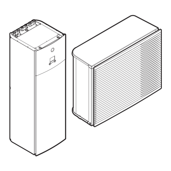
26 Feb 2019 22:19 Possible actions on this screen Go through the list of the main menu. Go to the main menu screen. Enable/disable breadcrumbs. EPRA14~18DAV3+W1 + ETVH16SU18+23EA6V Installer reference guide Daikin Altherma 3 H HT F 4P644738-1 – 2021.02... - Page 141 Outdoor unit Indoor unit / domestic hot water tank Floor-standing indoor unit with integrated tank Wall-mounted indoor unit Wall-mounted indoor unit with separated tank Water pressure EPRA14~18DAV3+W1 + ETVH16SU18+23EA6V Installer reference guide Daikin Altherma 3 H HT F 4P644738-1 – 2021.02...
- Page 142 "14.4.1 To display the help text in case of a malfunction" [ 253] for more information. If the corresponding operation (for example: space heating) is not active, the circle is greyed out. EPRA14~18DAV3+W1 + ETVH16SU18+23EA6V Installer reference guide Daikin Altherma 3 H HT F 4P644738-1 – 2021.02...
-
Page 143: Main Menu Screen
Displays data and information about the Information indoor unit. Installer settings Restriction: Only for the installer. Gives access to advanced settings. EPRA14~18DAV3+W1 + ETVH16SU18+23EA6V Installer reference guide Daikin Altherma 3 H HT F 4P644738-1 – 2021.02... -
Page 144: Menu Screen
[2] Main zone screen °C °C – – Room Main zone [3] Additional zone screen [5] Tank temperature screen °C °C – – Tank Additional zone EPRA14~18DAV3+W1 + ETVH16SU18+23EA6V Installer reference guide Daikin Altherma 3 H HT F 4P644738-1 – 2021.02... -
Page 145: Detailed Screen With Values
Confirm changes and proceed. 10.3.7 Schedule screen: Example This example shows how to set a room temperature schedule in heating mode for the main zone. EPRA14~18DAV3+W1 + ETVH16SU18+23EA6V Installer reference guide Daikin Altherma 3 H HT F 4P644738-1 – 2021.02... - Page 146 To clear the content of the week schedule 1 Select the name of the current schedule. User defined 1 2 Select Delete. Delete Rename Select 3 Select OK to confirm. EPRA14~18DAV3+W1 + ETVH16SU18+23EA6V Installer reference guide Daikin Altherma 3 H HT F 4P644738-1 – 2021.02...
- Page 147 In this example, Monday is the first day you programmed. Thus, the last programmed action is valid up to the first action of next Monday. EPRA14~18DAV3+W1 + ETVH16SU18+23EA6V Installer reference guide Daikin Altherma 3 H HT F 4P644738-1 – 2021.02...
- Page 148 5 Repeat this action for all other weekdays. — User defined 1 To program the schedule for Saturday and copy it to Sunday 1 Select Saturday. 2 Select Edit. EPRA14~18DAV3+W1 + ETVH16SU18+23EA6V Installer reference guide Daikin Altherma 3 H HT F 4P644738-1 – 2021.02...
- Page 149 The schedule name can contain up to 15 characters. 5 Confirm the new name. INFORMATION Not all schedules can be renamed. EPRA14~18DAV3+W1 + ETVH16SU18+23EA6V Installer reference guide Daikin Altherma 3 H HT F 4P644738-1 – 2021.02...
-
Page 150: Weather-Dependent Curve
See "10.4.4 Using weather-dependent curves" [ 153]. 10.4.2 2-points curve Define the weather-dependent curve with these two setpoints: ▪ Setpoint (X1, Y2) ▪ Setpoint (X2, Y1) EPRA14~18DAV3+W1 + ETVH16SU18+23EA6V Installer reference guide Daikin Altherma 3 H HT F 4P644738-1 – 2021.02... -
Page 151: Slope-Offset Curve
Examples Weather-dependent curve when slope is selected: EPRA14~18DAV3+W1 + ETVH16SU18+23EA6V Installer reference guide Daikin Altherma 3 H HT F 4P644738-1 – 2021.02... - Page 152 The icon corresponds to the heat emitter for that zone: ▪ : Underfloor heating ▪ : Fan coil unit ▪ : Radiator ▪ : Domestic hot water tank EPRA14~18DAV3+W1 + ETVH16SU18+23EA6V Installer reference guide Daikin Altherma 3 H HT F 4P644738-1 – 2021.02...
-
Page 153: Using Weather-Dependent Curves
Go to … Main zone – Heating [2.5] Main zone > Heating WD curve Main zone – Cooling [2.6] Main zone > Cooling WD curve EPRA14~18DAV3+W1 + ETVH16SU18+23EA6V Installer reference guide Daikin Altherma 3 H HT F 4P644738-1 – 2021.02... - Page 154 ↑ Cold Cold ↑ ↑ ↑ ↑ Cold ↓ ↑ ↓ ↑ — ↓ — ↓ Cold ↑ ↓ ↑ ↓ ↓ ↓ ↓ ↓ EPRA14~18DAV3+W1 + ETVH16SU18+23EA6V Installer reference guide Daikin Altherma 3 H HT F 4P644738-1 – 2021.02...
-
Page 155: Settings Menu
No: Room temperature is directly controlled by the user. ▪ Yes: Room temperature is controlled by a schedule and can be modified by the user. EPRA14~18DAV3+W1 + ETVH16SU18+23EA6V Installer reference guide Daikin Altherma 3 H HT F 4P644738-1 – 2021.02... - Page 156 Antifrost function via the backup heater. If the backup heater is not allowed for room frost protection during a U4 error, the room Antifrost setting MUST be disabled. EPRA14~18DAV3+W1 + ETVH16SU18+23EA6V Installer reference guide Daikin Altherma 3 H HT F 4P644738-1 – 2021.02...
- Page 157 Room frost protection is guaranteed by the normal logic. ▪ The external room thermostat is "Thermo ON" In case of 2 leaving water temperature zones: EPRA14~18DAV3+W1 + ETVH16SU18+23EA6V Installer reference guide Daikin Altherma 3 H HT F 4P644738-1 – 2021.02...
- Page 158 NOTICE When adjusting the room temperature ranges, all desired room temperatures are also adjusted to guarantee they are between the limits. EPRA14~18DAV3+W1 + ETVH16SU18+23EA6V Installer reference guide Daikin Altherma 3 H HT F 4P644738-1 – 2021.02...
-
Page 159: Main Zone
[9-0A] Heating comfort setpoint ▪ [3-07]~[3-06]°C [1.9.2] [9-0B] Cooling comfort setpoint ▪ [3-09]~[3-08]°C 10.5.3 Main zone Overview The following items are listed in the submenu: EPRA14~18DAV3+W1 + ETVH16SU18+23EA6V Installer reference guide Daikin Altherma 3 H HT F 4P644738-1 – 2021.02... - Page 160 Define a heating temperature schedule for the main zone via [2.2] Heating schedule. "10.3.7 Schedule screen: Example" [ 145]. Cooling schedule Define a cooling temperature schedule for the main zone via [2.3] Cooling schedule. "10.3.7 Schedule screen: Example" [ 145]. EPRA14~18DAV3+W1 + ETVH16SU18+23EA6V Installer reference guide Daikin Altherma 3 H HT F 4P644738-1 – 2021.02...
- Page 161 10°C. Heating WD curve Set weather-dependent heating for the main zone (if [2.4]=1 or 2): EPRA14~18DAV3+W1 + ETVH16SU18+23EA6V Installer reference guide Daikin Altherma 3 H HT F 4P644738-1 – 2021.02...
- Page 162 Note: This value should be lower than [1‑02] as for high outdoor temperatures less warm water is required. Cooling WD curve Set weather-dependent cooling for the main zone (if [2.4]=2): EPRA14~18DAV3+W1 + ETVH16SU18+23EA6V Installer reference guide Daikin Altherma 3 H HT F 4P644738-1 – 2021.02...
- Page 163 It is important to set Emitter type correctly and in accordance with your system layout. The target delta T for the main zone depends on it. EPRA14~18DAV3+W1 + ETVH16SU18+23EA6V Installer reference guide Daikin Altherma 3 H HT F 4P644738-1 – 2021.02...
- Page 164 Example underfloor heating: 40–5/2=37.5°C To compensate, you can: ▪ Increase the weather-dependent curve desired temperatures [2.5]. ▪ Enable leaving water temperature modulation and increase the maximum modulation [2.C]. EPRA14~18DAV3+W1 + ETVH16SU18+23EA6V Installer reference guide Daikin Altherma 3 H HT F 4P644738-1 – 2021.02...
- Page 165 Heating maximum: ▪ [2‑0C]=2 (emitter type main zone = radiator) 37°C~68°C ▪ Else: 37°C~55°C [2.8.3] [9-03] Cooling minimum: ▪ 5°C~18°C [2.8.4] [9-02] Cooling maximum: ▪ 18°C~22°C EPRA14~18DAV3+W1 + ETVH16SU18+23EA6V Installer reference guide Daikin Altherma 3 H HT F 4P644738-1 – 2021.02...
- Page 166 Leaving water temperature: Delta T In heating for the main zone, the target delta T (temperature difference) depends on the selected emitter type for the main zone. EPRA14~18DAV3+W1 + ETVH16SU18+23EA6V Installer reference guide Daikin Altherma 3 H HT F 4P644738-1 – 2021.02...
- Page 167 Additionally, also the desired leaving water temperature must be configured: if Modulation is enabled, the unit automatically calculates the desired leaving water temperature. These calculations are based on: EPRA14~18DAV3+W1 + ETVH16SU18+23EA6V Installer reference guide Daikin Altherma 3 H HT F 4P644738-1 – 2021.02...
- Page 168 1 leaving water temperature zone, connect the shut-off valve to the heating/cooling output. The shut off valve for the main leaving water temperature zone can close under these circumstances: EPRA14~18DAV3+W1 + ETVH16SU18+23EA6V Installer reference guide Daikin Altherma 3 H HT F 4P644738-1 – 2021.02...
-
Page 169: Additional Zone
150] and "10.4.3 Slope-offset curve" [ 151]. Code Description [2.E] ▪ 2-points ▪ Slope-Offset 10.5.4 Additional zone Overview The following items are listed in the submenu: EPRA14~18DAV3+W1 + ETVH16SU18+23EA6V Installer reference guide Daikin Altherma 3 H HT F 4P644738-1 – 2021.02... - Page 170 145]. Setpoint mode The setpoint mode of the additional zone can be independently set from the setpoint mode of the main zone. "Setpoint mode" [ 161]. EPRA14~18DAV3+W1 + ETVH16SU18+23EA6V Installer reference guide Daikin Altherma 3 H HT F 4P644738-1 – 2021.02...
- Page 171 Note: This value should be lower than [0‑01] as for high outdoor temperatures less warm water is required. Cooling WD curve Set weather-dependent cooling for the additional zone (if [3.4]=2): EPRA14~18DAV3+W1 + ETVH16SU18+23EA6V Installer reference guide Daikin Altherma 3 H HT F 4P644738-1 – 2021.02...
- Page 172 [9‑05]~[9‑06] [1‑0C] 0: Underfloor Maximum 55°C Variable (see [3.B.1]) heating 1: Fancoil unit Maximum 55°C Variable (see [3.B.1]) 2: Radiator Maximum 70°C Fixed 10°C EPRA14~18DAV3+W1 + ETVH16SU18+23EA6V Installer reference guide Daikin Altherma 3 H HT F 4P644738-1 – 2021.02...
- Page 173 (X2M/35a) ▪ 2: 2 contacts. Connected to 2 digital inputs (X2M/34a and X2M/35a) Leaving water temperature: Delta T For more information, see "10.5.3 Main zone" [ 159]. EPRA14~18DAV3+W1 + ETVH16SU18+23EA6V Installer reference guide Daikin Altherma 3 H HT F 4P644738-1 – 2021.02...
-
Page 174: Space Heating/Cooling
If your unit is a heating/cooling model, it can both heat up and cool down a space. You have to tell the system which operation mode to use. EPRA14~18DAV3+W1 + ETVH16SU18+23EA6V Installer reference guide Daikin Altherma 3 H HT F 4P644738-1 – 2021.02... - Page 175 To restrict automatic changeover according to a schedule Conditions: You set the space operation mode to Automatic. 1 Go to [4.2]: Space heating/cooling > Operation mode schedule. 2 Select a month. EPRA14~18DAV3+W1 + ETVH16SU18+23EA6V Installer reference guide Daikin Altherma 3 H HT F 4P644738-1 – 2021.02...
- Page 176 Besides the desired heating/cooling room temperature, the installer sets a hysteresis value (e.g. when in heating, this EPRA14~18DAV3+W1 + ETVH16SU18+23EA6V Installer reference guide Daikin Altherma 3 H HT F 4P644738-1 – 2021.02...
- Page 177 INFORMATION Mixing station. If your system layout contains 2 LWT zones, you need to install a mixing station in front of the main LWT zone. EPRA14~18DAV3+W1 + ETVH16SU18+23EA6V Installer reference guide Daikin Altherma 3 H HT F 4P644738-1 – 2021.02...
- Page 178 Make sure you set the emitter types for the main zone [2.7] and for the additional zone [3.7] correctly in accordance with the connected emitter. EPRA14~18DAV3+W1 + ETVH16SU18+23EA6V Installer reference guide Daikin Altherma 3 H HT F 4P644738-1 – 2021.02...
- Page 179 Sample is ONLY available in leaving water temperature control. a Space heating/cooling control b Off c On d LWT temperature e Actual f Desired g Pump operation EPRA14~18DAV3+W1 + ETVH16SU18+23EA6V Installer reference guide Daikin Altherma 3 H HT F 4P644738-1 – 2021.02...
- Page 180 Possible values: see below. [4.8.2] [9-0D] Restriction: Only displayed when the bizone kit (EKMIKPOA or EKMIKPHA) is installed. Pump limitation Additional zone Possible values: see below. Possible values: EPRA14~18DAV3+W1 + ETVH16SU18+23EA6V Installer reference guide Daikin Altherma 3 H HT F 4P644738-1 – 2021.02...
- Page 181 The maximum values depend on the unit type: [9-0D]/[9-0E]=0 [9-0D]/[9-0E]=1/5 a (kPa) a (kPa) b (l/min) b (l/min) [9-0D]/[9-0E]=2/6 [9-0D]/[9-0E]=3/7 a (kPa) a (kPa) b (l/min) b (l/min) EPRA14~18DAV3+W1 + ETVH16SU18+23EA6V Installer reference guide Daikin Altherma 3 H HT F 4P644738-1 – 2021.02...
- Page 182 0: No ▪ 1: increase 2°C, span 4°C ▪ 2: increase 4°C, span 4°C ▪ 3: increase 2°C, span 8°C ▪ 4: increase 4°C, span 8°C EPRA14~18DAV3+W1 + ETVH16SU18+23EA6V Installer reference guide Daikin Altherma 3 H HT F 4P644738-1 – 2021.02...
-
Page 183: Tank
[5.5] Schedule [5.6] Heat up mode [5.7] Disinfection [5.8] Maximum [5.9] Hysteresis [5.A] Hysteresis [5.B] Setpoint mode [5.C] WD curve [5.D] Margin [5.E] WD curve type EPRA14~18DAV3+W1 + ETVH16SU18+23EA6V Installer reference guide Daikin Altherma 3 H HT F 4P644738-1 – 2021.02... - Page 184 The storage economic temperature denotes the lower desired tank temperature. It is the desired temperature when a storage economic action is scheduled (preferably during day). EPRA14~18DAV3+W1 + ETVH16SU18+23EA6V Installer reference guide Daikin Altherma 3 H HT F 4P644738-1 – 2021.02...
- Page 185 CAUTION The disinfection function settings MUST be configured by the installer according to the applicable legislation. EPRA14~18DAV3+W1 + ETVH16SU18+23EA6V Installer reference guide Daikin Altherma 3 H HT F 4P644738-1 – 2021.02...
- Page 186 CAUTION Be sure that the disinfection function start time [5.7.3] with defined duration [5.7.5] is NOT interrupted by possible domestic hot water demand. EPRA14~18DAV3+W1 + ETVH16SU18+23EA6V Installer reference guide Daikin Altherma 3 H HT F 4P644738-1 – 2021.02...
- Page 187 The minimum ON temperature is 20°C, even if setpoint hysteresis is smaller than 20°C. Code Description [5.9] [6-00] Heat pump ON hysteresis ▪ 2°C~40°C EPRA14~18DAV3+W1 + ETVH16SU18+23EA6V Installer reference guide Daikin Altherma 3 H HT F 4P644738-1 – 2021.02...
- Page 188 (according to the weather dependent curve). During weather dependent operation, the end-user cannot adjust the desired tank temperature on the user interface. Also see "10.4 Weather-dependent curve" [ 150]. EPRA14~18DAV3+W1 + ETVH16SU18+23EA6V Installer reference guide Daikin Altherma 3 H HT F 4P644738-1 – 2021.02...
- Page 189 Maximum heat pump temperature at sensor in domestic hot water tank HP MAX Heat pump OFF temperature (T −[6-01]) HP OFF HP MAX Heat pump ON temperature (T −[6-00]) HP ON HP OFF EPRA14~18DAV3+W1 + ETVH16SU18+23EA6V Installer reference guide Daikin Altherma 3 H HT F 4P644738-1 – 2021.02...
-
Page 190: User Settings
[7] User settings Space heating/cooling Tank [7.1] Language User settings [7.2] Time/date Information Installer settings [7.3] Holiday [7.4] Quiet [7.5] Electricity price [7.6] Gas price EPRA14~18DAV3+W1 + ETVH16SU18+23EA6V Installer reference guide Daikin Altherma 3 H HT F 4P644738-1 – 2021.02... - Page 191 ▪ Select On. 2 Set the first day of your holiday. — ▪ Go to [7.3.2]: From. ▪ Select a date. ▪ Confirm the changes. EPRA14~18DAV3+W1 + ETVH16SU18+23EA6V Installer reference guide Daikin Altherma 3 H HT F 4P644738-1 – 2021.02...
- Page 192 Go to [7.4.3] Level and select the applicable quiet mode level. Example: Most quiet. Result: The unit always runs in the selected quiet mode level. The user cannot change this. EPRA14~18DAV3+W1 + ETVH16SU18+23EA6V Installer reference guide Daikin Altherma 3 H HT F 4P644738-1 – 2021.02...
- Page 193 INFORMATION Price value ranging from 0.00~990 valuta/kWh (with 2 significant values). INFORMATION If no schedule is set, the Electricity price for High is taken into account. EPRA14~18DAV3+W1 + ETVH16SU18+23EA6V Installer reference guide Daikin Altherma 3 H HT F 4P644738-1 – 2021.02...
- Page 194 Renewable heat incentive per kWh Calculation of the gas price Gas price=Actual gas price+(Incentive/kWh×0.9) Gas price=4.08+(5×0.9) Gas price=8.58 Calculation of the electricity price Electricity price=Actual electricity price+Incentive/kWh EPRA14~18DAV3+W1 + ETVH16SU18+23EA6V Installer reference guide Daikin Altherma 3 H HT F 4P644738-1 – 2021.02...
-
Page 195: Information
In menu… You can read out… [8.1] Energy data Produced energy, consumed electricity, and consumed gas [8.2] Malfunction history Malfunction history [8.3] Dealer information Contact/helpdesk number EPRA14~18DAV3+W1 + ETVH16SU18+23EA6V Installer reference guide Daikin Altherma 3 H HT F 4P644738-1 – 2021.02... -
Page 196: Installer Settings
[9.D] Alarm output [9.E] Auto restart [9.F] Power saving function [9.G] Disable protections [9.H] Forced defrost [9.I] Overview field settings [9.N] Export MMI settings [9.P] Bizone kit EPRA14~18DAV3+W1 + ETVH16SU18+23EA6V Installer reference guide Daikin Altherma 3 H HT F 4P644738-1 – 2021.02... - Page 197 When turned on, the pump runs and makes sure hot water is instantly available at the tap. To save energy, only turn on the pump during periods of the day when instant hot water is necessary. EPRA14~18DAV3+W1 + ETVH16SU18+23EA6V Installer reference guide Daikin Altherma 3 H HT F 4P644738-1 – 2021.02...
- Page 198 [6‑03]+[6‑04]. INFORMATION If [4‑0A]=3 and emergency mode is active, the power usage of the backup heater is maximal and equal to 2×[6‑03]+[6‑04]. EPRA14~18DAV3+W1 + ETVH16SU18+23EA6V Installer reference guide Daikin Altherma 3 H HT F 4P644738-1 – 2021.02...
- Page 199 Only for systems with integrated domestic hot water tank: If the storage temperature setpoint is higher than 50°C, Daikin recommends NOT to disable the backup heater second step because it will have a big impact on the required time for the unit to heat up the domestic hot water tank.
- Page 200 NOT confirm emergency operation. EPRA14~18DAV3+W1 + ETVH16SU18+23EA6V Installer reference guide Daikin Altherma 3 H HT F 4P644738-1 – 2021.02...
- Page 201 [5‑01] Equilibrium temperature and [5‑03] Space heating priority temperature are related to backup heater. So, you must set [5‑03] equal or a few degrees higher than [5‑01]. EPRA14~18DAV3+W1 + ETVH16SU18+23EA6V Installer reference guide Daikin Altherma 3 H HT F 4P644738-1 – 2021.02...
- Page 202 [8-04]. Range: 0~10 hours Remark: The minimum time is 0.5 hours even when the selected value is 0. EPRA14~18DAV3+W1 + ETVH16SU18+23EA6V Installer reference guide Daikin Altherma 3 H HT F 4P644738-1 – 2021.02...
- Page 203 ONLY disable water pipe freeze prevention if glycol is used. For more information on freeze protection by glycol, see "8.2.7 To protect the water circuit against freezing" [ 97]. EPRA14~18DAV3+W1 + ETVH16SU18+23EA6V Installer reference guide Daikin Altherma 3 H HT F 4P644738-1 – 2021.02...
- Page 204 Therefore, always enable the auto restart function. ▪ 3 Smart grid: A Smart Grid is connected to the system EPRA14~18DAV3+W1 + ETVH16SU18+23EA6V Installer reference guide Daikin Altherma 3 H HT F 4P644738-1 – 2021.02...
- Page 205 Yes: The extra energy from the photovoltaic panels is buffered in the DHW tank, and in the space heating/cooling circuit (i.e. heat up or cool down the room). EPRA14~18DAV3+W1 + ETVH16SU18+23EA6V Installer reference guide Daikin Altherma 3 H HT F 4P644738-1 – 2021.02...
- Page 206 The safety functions (water pipe freeze prevention, drain prevention, room frost protection, tank disinfection) and defrost are NOT overruled (capacity will not be limited for these functions) Recommended on: EPRA14~18DAV3+W1 + ETVH16SU18+23EA6V Installer reference guide Daikin Altherma 3 H HT F 4P644738-1 – 2021.02...
- Page 207 Limit when [9.9.1]=Continuous and [9.9.2]=Amp: Code Description [9.9.3] [5-05] Limit: Only applicable in case of full time current limitation mode. 0 A~50 A Limits when [9.9.1]=Inputs and [9.9.2]=Amp: EPRA14~18DAV3+W1 + ETVH16SU18+23EA6V Installer reference guide Daikin Altherma 3 H HT F 4P644738-1 – 2021.02...
- Page 208 Note: In case power consumption control is DISABLED (for all models) the setting [4‑01] defines whether backup heater and booster heater can operate simultaneously, or if the booster heater/backup heater has priority over the backup heater/booster heater. EPRA14~18DAV3+W1 + ETVH16SU18+23EA6V Installer reference guide Daikin Altherma 3 H HT F 4P644738-1 – 2021.02...
- Page 209 ▪ 0 None: NOT installed ▪ 1 1/10kWh: Installed ▪ 2 1/kWh: Installed ▪ 3 10/kWh: Installed ▪ 4 100/kWh: Installed ▪ 5 1000/kWh: Installed EPRA14~18DAV3+W1 + ETVH16SU18+23EA6V Installer reference guide Daikin Altherma 3 H HT F 4P644738-1 – 2021.02...
- Page 210 Code Description [9.B.2] [2-0B] Ext. amb. sensor offset: Offset on the ambient temperature measured on the external outdoor temperature sensor. ▪ –5°C~5°C, step 0.5°C EPRA14~18DAV3+W1 + ETVH16SU18+23EA6V Installer reference guide Daikin Altherma 3 H HT F 4P644738-1 – 2021.02...
- Page 211 If Bivalent is disabled: Space heating is only done by the heat pump within the operation range. The permission signal for the auxiliary boiler is always inactive. EPRA14~18DAV3+W1 + ETVH16SU18+23EA6V Installer reference guide Daikin Altherma 3 H HT F 4P644738-1 – 2021.02...
- Page 212 To determine the value of [C‑03], proceed as follows: 1 Determine the COP (= coefficient of performance) using the formula: EPRA14~18DAV3+W1 + ETVH16SU18+23EA6V Installer reference guide Daikin Altherma 3 H HT F 4P644738-1 – 2021.02...
- Page 213 User settings > Electricity price > [7.6] User settings > Gas price Boiler efficiency Depending on the used boiler, this should be chosen as follows: EPRA14~18DAV3+W1 + ETVH16SU18+23EA6V Installer reference guide Daikin Altherma 3 H HT F 4P644738-1 – 2021.02...
- Page 214 Code Description [9.E] [3-00] Auto restart: ▪ 0: Manual ▪ 1: Automatic EPRA14~18DAV3+W1 + ETVH16SU18+23EA6V Installer reference guide Daikin Altherma 3 H HT F 4P644738-1 – 2021.02...
- Page 215 1: Yes Forced defrost Forced defrost Manually start a defrost operation. Code Description [9.H] Do you want to start a defrost operation? ▪ Back ▪ EPRA14~18DAV3+W1 + ETVH16SU18+23EA6V Installer reference guide Daikin Altherma 3 H HT F 4P644738-1 – 2021.02...
- Page 216 2 On the user interface, go to [9.N] Export MMI settings. 3 Select OK. 4 Remove the USB memory stick and close the user interface — panel. EPRA14~18DAV3+W1 + ETVH16SU18+23EA6V Installer reference guide Daikin Altherma 3 H HT F 4P644738-1 – 2021.02...
- Page 217 Additional zone pump fixed PWM The speed of the additional zone pump can be fixed with this setting. EPRA14~18DAV3+W1 + ETVH16SU18+23EA6V Installer reference guide Daikin Altherma 3 H HT F 4P644738-1 – 2021.02...
-
Page 218: Commissioning
About commissioning See: "11 Commissioning" [ 225] 10.5.11 User profile [B] User profile: See "To change the user permission level" [ 135]. Installer settings Commissioning User profile Operation Malfunctioning EPRA14~18DAV3+W1 + ETVH16SU18+23EA6V Installer reference guide Daikin Altherma 3 H HT F 4P644738-1 – 2021.02... -
Page 219: Operation
[D.4] Device info About the WLAN cartridge The WLAN cartridge connects the system to the internet. The user you can then control the system via the Daikin Residential Controller app. This needs the following components: WLAN cartridge The WLAN cartridge needs to be inserted in the user interface. - Page 220 See: http://www.onlinecontroller.daikineurope.com/ Configuration To configure the Daikin Residential Controller app, follow the in-app instructions. While doing this, the following actions and information are needed on the user interface: Mode: Turn AP mode ON (= WLAN adapter active as access point) or OFF.
- Page 221 Configuration Code Description [D.6] Cloud connection: ▪ Not connected ▪ Connected EPRA14~18DAV3+W1 + ETVH16SU18+23EA6V Installer reference guide Daikin Altherma 3 H HT F 4P644738-1 – 2021.02...
-
Page 222: Menu Structure: Overview User Settings
(**) Only accessible by installer (***) Only applicable when WLAN is installed INFORMATION Depending on the selected installer settings and unit type, settings will be visible/ invisible. EPRA14~18DAV3+W1 + ETVH16SU18+23EA6V Installer reference guide Daikin Altherma 3 H HT F 4P644738-1 – 2021.02... -
Page 223: Menu Structure: Overview Installer Settings
(*) Only applicable in Swedish language. INFORMATION Solar kit settings are shown but are NOT applicable for this unit. Settings shall NOT be used or changed. EPRA14~18DAV3+W1 + ETVH16SU18+23EA6V Installer reference guide Daikin Altherma 3 H HT F 4P644738-1 – 2021.02... - Page 224 Configuration INFORMATION Depending on the selected installer settings and unit type, settings will be visible/ invisible. EPRA14~18DAV3+W1 + ETVH16SU18+23EA6V Installer reference guide Daikin Altherma 3 H HT F 4P644738-1 – 2021.02...
-
Page 225: Commissioning
11 Commissioning NOTICE General commissioning checklist. Next to the commissioning instructions in this chapter, a general commissioning checklist is also available on the Daikin Business Portal (authentication required). The general commissioning checklist is complementary to the instructions in this chapter and can be used as a guideline and reporting template during the commissioning and hand-over to the user. -
Page 226: Precautions When Commissioning
There are NO damaged components or squeezed pipes on the inside of the indoor and outdoor units. Backup heater circuit breaker F1B (field supply) is turned ON. The correct pipe size is installed and the pipes are properly insulated. EPRA14~18DAV3+W1 + ETVH16SU18+23EA6V Installer reference guide Daikin Altherma 3 H HT F 4P644738-1 – 2021.02... -
Page 227: Checklist During Commissioning
— reach the minimum required flow rate + 2 l/min. During pump test run, the unit can operate below the minimum required flow rate. EPRA14~18DAV3+W1 + ETVH16SU18+23EA6V Installer reference guide Daikin Altherma 3 H HT F 4P644738-1 – 2021.02... -
Page 228: Air Purge Function
3 In the menu, set Type = Manual. 4 Select Start air purge. 5 Select OK to confirm. Result: The air purge starts. It stops automatically when ready. EPRA14~18DAV3+W1 + ETVH16SU18+23EA6V Installer reference guide Daikin Altherma 3 H HT F 4P644738-1 – 2021.02... -
Page 229: Operation Test Run
"To change — the user permission level" [ 135]. 2 Go to [A.1]: Commissioning > Operation test run. 3 Select a test from the list. Example: Heating. EPRA14~18DAV3+W1 + ETVH16SU18+23EA6V Installer reference guide Daikin Altherma 3 H HT F 4P644738-1 – 2021.02... -
Page 230: Actuator Test Run
1 In the menu, go to Stop test run. 2 Select OK to confirm. Possible actuator test runs ▪ Backup heater 1 test ▪ Backup heater 2 test ▪ Pump test EPRA14~18DAV3+W1 + ETVH16SU18+23EA6V Installer reference guide Daikin Altherma 3 H HT F 4P644738-1 – 2021.02... -
Page 231: Underfloor Heating Screed Dryout
The installer can program up to 20 steps. For each step he needs to enter: 1 the duration in hours, up to 72 hours, 2 the desired leaving water temperature, up to 55°C. Example: EPRA14~18DAV3+W1 + ETVH16SU18+23EA6V Installer reference guide Daikin Altherma 3 H HT F 4P644738-1 – 2021.02... - Page 232 [2‑06] to "0", and KEEP it disabled until the screed dryout has finished. Ignoring this notice will result in cracking of the screed. EPRA14~18DAV3+W1 + ETVH16SU18+23EA6V Installer reference guide Daikin Altherma 3 H HT F 4P644738-1 – 2021.02...
- Page 233 In case of a power failure, the U3 error is not generated. When power is restored, the unit automatically restarts the latest step and continues the program. EPRA14~18DAV3+W1 + ETVH16SU18+23EA6V Installer reference guide Daikin Altherma 3 H HT F 4P644738-1 – 2021.02...
- Page 234 If the UFH screed dryout program was stopped due to a power failure and the power resumes, the program will automatically restart the last implemented step. EPRA14~18DAV3+W1 + ETVH16SU18+23EA6V Installer reference guide Daikin Altherma 3 H HT F 4P644738-1 – 2021.02...
-
Page 235: Hand-Over To The User
Show the user what to do for the maintenance of the unit. ▪ Explain the user about energy saving tips as described in the operation manual. EPRA14~18DAV3+W1 + ETVH16SU18+23EA6V Installer reference guide Daikin Altherma 3 H HT F 4P644738-1 – 2021.02... -
Page 236: Maintenance And Service
Before performing any maintenance or service work, touch a metal part of the unit in order to eliminate static electricity and to protect the PCB. EPRA14~18DAV3+W1 + ETVH16SU18+23EA6V Installer reference guide Daikin Altherma 3 H HT F 4P644738-1 – 2021.02... -
Page 237: Yearly Maintenance
▪ Temperature and pressure relief valve 13.3.4 Yearly maintenance indoor unit: instructions Water pressure Keep water pressure above 1 bar. If it is lower, add water. EPRA14~18DAV3+W1 + ETVH16SU18+23EA6V Installer reference guide Daikin Altherma 3 H HT F 4P644738-1 – 2021.02... - Page 238 "13.6.3 To install the water filter" [ 244] Water pressure relief valve Open the valve and check if it operates correctly. The water may be very hot! Checkpoints are: EPRA14~18DAV3+W1 + ETVH16SU18+23EA6V Installer reference guide Daikin Altherma 3 H HT F 4P644738-1 – 2021.02...
- Page 239 For this reason, descaling of the heat exchanger may be required at certain intervals. EPRA14~18DAV3+W1 + ETVH16SU18+23EA6V Installer reference guide Daikin Altherma 3 H HT F 4P644738-1 – 2021.02...
- Page 240 Check for correct operation of the temperature and pressure relief valve. Manually operate the temperature and pressure relief valve to ensure free water flow through discharge pipe. Turn knob left. EPRA14~18DAV3+W1 + ETVH16SU18+23EA6V Installer reference guide Daikin Altherma 3 H HT F 4P644738-1 – 2021.02...
-
Page 241: To Drain The Domestic Hot Water Tank
6 Use a drain hose and a pump to drain the tank via the access point. 7 Tightening torques for installation: Item Tightening torque Tube connection 30 N•m Temperature and pressure relief valve 40 N•m EPRA14~18DAV3+W1 + ETVH16SU18+23EA6V Installer reference guide Daikin Altherma 3 H HT F 4P644738-1 – 2021.02... -
Page 242: To Inspect The Inside Of The Domestic Hot Water Tank
▪ "13.6.1 To remove the water filter" [ 243] ▪ "13.6.2 To clean the water filter in case of trouble" [ 243] ▪ "13.6.3 To install the water filter" [ 244] EPRA14~18DAV3+W1 + ETVH16SU18+23EA6V Installer reference guide Daikin Altherma 3 H HT F 4P644738-1 – 2021.02... -
Page 243: To Remove The Water Filter
Opening the magnetic filter/dirt separator is ONLY required in case of severe issues. Preferably this action is never to be done during the complete lifetime of the magnetic filter/dirt separator. EPRA14~18DAV3+W1 + ETVH16SU18+23EA6V Installer reference guide Daikin Altherma 3 H HT F 4P644738-1 – 2021.02... -
Page 244: To Install The Water Filter
Check the condition of the O-rings and replace if needed. Apply water to the O-rings before installation. 1 Install the water filter in the correct location. EPRA14~18DAV3+W1 + ETVH16SU18+23EA6V Installer reference guide Daikin Altherma 3 H HT F 4P644738-1 – 2021.02... - Page 245 Make sure to open the valve (if equipped) towards the expansion vessel, otherwise the overpressure will be generated. 5 Open the stop valves and add water to the water circuit if needed. EPRA14~18DAV3+W1 + ETVH16SU18+23EA6V Installer reference guide Daikin Altherma 3 H HT F 4P644738-1 – 2021.02...
-
Page 246: Troubleshooting
If you are unable to find the cause of the problem, call your dealer. DANGER: RISK OF ELECTROCUTION EPRA14~18DAV3+W1 + ETVH16SU18+23EA6V Installer reference guide Daikin Altherma 3 H HT F 4P644738-1 – 2021.02... -
Page 247: Solving Problems Based On Symptoms
Make sure that the water volume in the too low installation is above the minimum required value (see "8.1.3 To check the water volume and flow rate" [ 87]). EPRA14~18DAV3+W1 + ETVH16SU18+23EA6V Installer reference guide Daikin Altherma 3 H HT F 4P644738-1 – 2021.02... -
Page 248: Symptom: Hot Water Does Not Reach The Desired Temperature
Perform hydraulic balancing to assure that the flow is correctly distributed between the emitters. hydraulic balancing sufficient, change pump limitation settings ([9-0D] and [9-0E] if applicable). EPRA14~18DAV3+W1 + ETVH16SU18+23EA6V Installer reference guide Daikin Altherma 3 H HT F 4P644738-1 – 2021.02... -
Page 249: Symptom: The Pump Is Blocked
Purge air manually (see "To perform a manual air purge" [ 228]) or use the automatic air purge function (see "To perform an automatic air purge" [ 229]). EPRA14~18DAV3+W1 + ETVH16SU18+23EA6V Installer reference guide Daikin Altherma 3 H HT F 4P644738-1 – 2021.02... -
Page 250: Symptom: The Pressure Relief Valve Opens
0 m. The maximum water circuit head is 10 m. Check the installation requirements. EPRA14~18DAV3+W1 + ETVH16SU18+23EA6V Installer reference guide Daikin Altherma 3 H HT F 4P644738-1 – 2021.02... -
Page 251: Symptom: The Water Pressure Relief Valve Leaks
> Backup heater > Equilibrium temperature [5‑01] There is air in the system. Purge air manually or automatically. See the air purge function in the chapter "11 Commissioning" [ 225]. EPRA14~18DAV3+W1 + ETVH16SU18+23EA6V Installer reference guide Daikin Altherma 3 H HT F 4P644738-1 – 2021.02... -
Page 252: Symptom: The Pressure At The Tapping Point Is Temporarily Unusually High
The disinfection operation was stopped Do NOT stop tank operation during manually: [C.3] Operation > Tank was disinfection. turned off during disinfection. EPRA14~18DAV3+W1 + ETVH16SU18+23EA6V Installer reference guide Daikin Altherma 3 H HT F 4P644738-1 – 2021.02... -
Page 253: Solving Problems Based On Error Codes
Leaving water temperature sensor problem 81-01 Mixed water thermistor abnormality. 81-06 Entering water temperature thermistor abnormality (indoor unit) 89-01 Heat exchanger freeze-up protection activated during defrost (error) EPRA14~18DAV3+W1 + ETVH16SU18+23EA6V Installer reference guide Daikin Altherma 3 H HT F 4P644738-1 – 2021.02... - Page 254 OU: Overheat of inverter compressor motor E6-00 OU: Compressor startup defect E7-00 OU: Malfunction of outdoor unit fan motor E8-00 OU: Power input overvoltage E9-00 Malfunction of electronic expansion valve EPRA14~18DAV3+W1 + ETVH16SU18+23EA6V Installer reference guide Daikin Altherma 3 H HT F 4P644738-1 – 2021.02...
- Page 255 JC-01 Evaporator pressure abnormality L1-00 Malfunction of INV PCB L3-00 OU: Electrical box temperature rise problem L4-00 OU: Malfunction of inverter radiating fin temperature rise EPRA14~18DAV3+W1 + ETVH16SU18+23EA6V Installer reference guide Daikin Altherma 3 H HT F 4P644738-1 – 2021.02...
- Page 256 Indoor unit, outdoor unit matching problem UA-16 Extension/hydro communication problem UA-17 Tank type problem UA-21 Extension/hydro mismatch problem UF-00 Reversed piping or bad communication wiring detection EPRA14~18DAV3+W1 + ETVH16SU18+23EA6V Installer reference guide Daikin Altherma 3 H HT F 4P644738-1 – 2021.02...
- Page 257 If the software is not successfully updated then you must make sure that your USB device has the FAT32 format. INFORMATION The user interface will display how to reset an error code. EPRA14~18DAV3+W1 + ETVH16SU18+23EA6V Installer reference guide Daikin Altherma 3 H HT F 4P644738-1 – 2021.02...
-
Page 258: Disposal
78] 1 Make sure the unit is not running. 2 Activate the recovery mode (see "15.1.2 Recovery mode" [ 260]). Result: The unit opens the valves (Y*). EPRA14~18DAV3+W1 + ETVH16SU18+23EA6V Installer reference guide Daikin Altherma 3 H HT F 4P644738-1 – 2021.02... -
Page 259: To Manually Open The Electronic Expansion Valves
3 Turn the EEV magnet anticlockwise to the fully open position of the valve. If you are not sure about what the open position is, turn the valve in its middle position so that refrigerant can pass. EPRA14~18DAV3+W1 + ETVH16SU18+23EA6V Installer reference guide Daikin Altherma 3 H HT F 4P644738-1 – 2021.02... -
Page 260: Recovery Mode
Press BS3 once. Press BS2 once. Press BS3 once. Press BS3 once. The flashing H1P indicates the recovery mode has been correctly selected and is activated. EPRA14~18DAV3+W1 + ETVH16SU18+23EA6V Installer reference guide Daikin Altherma 3 H HT F 4P644738-1 – 2021.02... - Page 261 / solenoid valves to their initial state. INFORMATION Power OFF. When power is turned OFF and turned ON again, the recovery mode is deactivated automatically. EPRA14~18DAV3+W1 + ETVH16SU18+23EA6V Installer reference guide Daikin Altherma 3 H HT F 4P644738-1 – 2021.02...
-
Page 262: Technical Data
Technical data 16 Technical data A subset of the latest technical data is available on the regional Daikin website (publicly accessible). The full set of latest technical data is available on the Daikin Business Portal (authentication required). In this chapter 16.1... -
Page 263: Service Space: Outdoor Unit
≥300 ≥100 ≥500 (mm) 3D124412 English Translation General General No top-side obstacle No top-side obstacle Top-side obstacle Top-side obstacle Wall height unrestricted Wall height unrestricted EPRA14~18DAV3+W1 + ETVH16SU18+23EA6V Installer reference guide Daikin Altherma 3 H HT F 4P644738-1 – 2021.02... -
Page 264: Piping Diagram: Outdoor Unit
Y3E Electronic expansion valve (injection) Y1S Solenoid valve (4-way valve) Y2S Solenoid valve (low pressure bypass) Y3S Solenoid valve (hot gas bypass) Y4S Solenoid valve (liquid injection) EPRA14~18DAV3+W1 + ETVH16SU18+23EA6V Installer reference guide Daikin Altherma 3 H HT F 4P644738-1 – 2021.02... -
Page 265: Piping Diagram: Indoor Unit
R1T Thermistor (water IN) R2T Thermistor (backup heater – water OUT) R5T, R8T Thermistor (tank) S1L Flow switch Screw connection Flare connection Quick coupling Brazed connection EPRA14~18DAV3+W1 + ETVH16SU18+23EA6V Installer reference guide Daikin Altherma 3 H HT F 4P644738-1 – 2021.02... -
Page 266: Wiring Diagram: Outdoor Unit
Right side view See note *** See note *** Notes: Symbols: Live Neutral Protective earth Noiseless earth Field wiring Option Terminal strip Terminal Connector Connection EPRA14~18DAV3+W1 + ETVH16SU18+23EA6V Installer reference guide Daikin Altherma 3 H HT F 4P644738-1 – 2021.02... - Page 267 Light-emitting diode (service monitor is orange) HAP (A1P) Light-emitting diode (service monitor is green) K1R (A1P) Magnetic relay (Y1S) K1R (A4P) Magnetic relay (E1HHEX~E3HHEX) K2R (A1P) Magnetic relay (Y2S) EPRA14~18DAV3+W1 + ETVH16SU18+23EA6V Installer reference guide Daikin Altherma 3 H HT F 4P644738-1 – 2021.02...
- Page 268 Insulated Gate Bipolar Transistor (IGBT) X1M, X2M Terminal strip Electronic expansion valve (main) Electronic expansion valve (injection) Solenoid valve (4‑way valve) Solenoid valve (low pressure bypass) EPRA14~18DAV3+W1 + ETVH16SU18+23EA6V Installer reference guide Daikin Altherma 3 H HT F 4P644738-1 – 2021.02...
- Page 269 Earth leakage circuit breaker (30 mA) (field supply) R1, R2 (A2P) Resistor Thermistor (outdoor air) Thermistor (compressor discharge) Thermistor (compressor suction) Thermistor (air heat exchanger, distributor) Thermistor (air heat exchanger, middle) EPRA14~18DAV3+W1 + ETVH16SU18+23EA6V Installer reference guide Daikin Altherma 3 H HT F 4P644738-1 – 2021.02...
- Page 270 Solenoid valve (4‑way valve) Solenoid valve (low pressure bypass) Solenoid valve (hot gas bypass) Solenoid valve (liquid injection) Z1C~Z10C Noise filter (ferrite core) Z1F~Z4F (A1P, A3P) Noise filter EPRA14~18DAV3+W1 + ETVH16SU18+23EA6V Installer reference guide Daikin Altherma 3 H HT F 4P644738-1 – 2021.02...
-
Page 271: Wiring Diagram: Indoor Unit
Demand PCB Demand PCB Safety thermostat Safety thermostat Smart Grid Smart grid WLAN module WLAN module WLAN cartridge WLAN cartridge Bizone mixing kit Bizone mixing kit EPRA14~18DAV3+W1 + ETVH16SU18+23EA6V Installer reference guide Daikin Altherma 3 H HT F 4P644738-1 – 2021.02... - Page 272 Relay on PCB # Domestic hot water pump # 2-way valve for cooling mode PC (A15P) * Power circuit PHC1 (A4P) * Optocoupler input circuit EPRA14~18DAV3+W1 + ETVH16SU18+23EA6V Installer reference guide Daikin Altherma 3 H HT F 4P644738-1 – 2021.02...
- Page 273 Use normal kWh rate power supply for indoor unit indoor unit (2) Backup heater power supply (2) Backup heater power supply Only for *** Only for *** EPRA14~18DAV3+W1 + ETVH16SU18+23EA6V Installer reference guide Daikin Altherma 3 H HT F 4P644738-1 – 2021.02...
- Page 274 (7) Option PCBs Alarm output Alarm output Changeover to ext. heat source Changeover to external heat source Max. load Maximum load Min. load Minimum load EPRA14~18DAV3+W1 + ETVH16SU18+23EA6V Installer reference guide Daikin Altherma 3 H HT F 4P644738-1 – 2021.02...
- Page 275 Only for heat pump convector Only for wired On/OFF thermostat Only for wired On/OFF thermostat Only for wireless On/OFF thermostat Only for wireless On/OFF thermostat EPRA14~18DAV3+W1 + ETVH16SU18+23EA6V Installer reference guide Daikin Altherma 3 H HT F 4P644738-1 – 2021.02...
- Page 276 A3P: X11M: 3-4-5-6 signal main & add: X2M: 3-4 Only for Human Comfort Interface 2 core 2×0.75 X5M: 11-12 A14P: P1-P2 user interface communication 4D133216A EPRA14~18DAV3+W1 + ETVH16SU18+23EA6V Installer reference guide Daikin Altherma 3 H HT F 4P644738-1 – 2021.02...
-
Page 277: Technical Specifications: Domestic Hot Water Tank
180 l 289 kg ETVH16SU18EA6V ETVH16SU23EA6V 220 l 338 kg ■ Maximum design pressure: 10 bar ■ Rated volume heat exchanger: 9.1 l 4P647876-1A EPRA14~18DAV3+W1 + ETVH16SU18+23EA6V Installer reference guide Daikin Altherma 3 H HT F 4P644738-1 – 2021.02... -
Page 278: Esp Curve: Indoor Unit
See also the minimum and maximum allowed water flow range in the technical specifications. ▪ Make sure water quality complies with EU directive 2020/2184. EPRA14~18DAV3+W1 + ETVH16SU18+23EA6V Installer reference guide Daikin Altherma 3 H HT F 4P644738-1 – 2021.02... -
Page 279: Glossary
Optional equipment Equipment made or approved by Daikin that can be combined with the product according to the instructions in the accompanying documentation. Field supply Equipment NOT made by Daikin that can be combined with the product according to the instructions in the accompanying documentation. -
Page 280: Field Settings Table
1/13 0F41 Field settings table [8.7.5] = ..Applicable indoor units ETBH16EF6V ETBH16EF9W ETBX16EF6V ETBX16EF9W ETVH16S18EA6V ETVH16S23EA6V ETVH16S18EA9W ETVH16S23EA9W ETVX16S18EA6V ETVX16S23EA6V ETVX16S18EA9W ETVX16S23EA9W ETVH16SU18EA6V ETVH16SU23EA6V Notes (*1) *6V (*2) *9W (*3) ETB* (*4) ETV* (*5) *X* (*6) *H* (*7) *SU* 4P644734-1 - 2021.02... - Page 281 2/13 Installer setting at variance with Field settings table default value Breadcrumb Field code Setting name Range, step Date Value Default value Room └─ Antifrost 1.4.1 [2-06] Activation 0: Disabled 1: Enabled 1.4.2 [2-05] Room setpoint 4~16°C, step: 1°C 8°C └─...
- Page 282 3/13 Installer setting at variance with Field settings table default value Breadcrumb Field code Setting name Range, step Date Value Default value 2.C.2 [8-06] Max modulation 0~10°C, step: 1°C 5°C └─ Shut off valve 2.D.1 [F-0B] During thermo 0: No 1: Yes 2.D.2 [F-0C]...
- Page 283 4/13 Installer setting at variance with Field settings table default value Breadcrumb Field code Setting name Range, step Date Value Default value [9-04] Overshoot 1~4°C, step: 1°C 1°C [2-06] Antifrost 0: Disabled 1: Enabled Tank [6-0A] Comfort setpoint 30~[6-0E]°C, step: 1°C 60°C [6-0B] Eco setpoint...
- Page 284 5/13 Installer setting at variance with Field settings table default value Breadcrumb Field code Setting name Range, step Date Value Default value 9.1.3.4 [4-06] Emergency 0: Manual 1: Automatic 2: Auto red SH/ DHW ON 3: Auto red SH/ DHW OFF 4: Auto normal SH/ DHW OFF 9.1.3.5 [7-02]...
- Page 285 6/13 Installer setting at variance with Field settings table default value Breadcrumb Field code Setting name Range, step Date Value Default value 9.1.A [0-07] Low ambient temp. for LWT add zone cooling WD curve. 10~25°C, step: 1°C 20°C └─ Tank 9.1.B.1 [6-0D] Heat up mode...
- Page 286 7/13 Installer setting at variance with Field settings table default value Breadcrumb Field code Setting name Range, step Date Value Default value 9.8.6 Allow electric heaters 0: No 1: Yes 9.8.7 Enable Room buffering 0: No 1: Yes 9.8.8 Limit setting kW 0~20 kW, step: 0,5 kW 20 kW └─...
- Page 287 8/13 Installer setting at variance with Field settings table default value Breadcrumb Field code Setting name Range, step Date Value Default value [0-06] High ambient temp. for LWT add zone cooling WD curve. 25~43°C, step: 1°C 35°C [0-07] Low ambient temp. for LWT add zone cooling WD curve. 10~25°C, step: 1°C 20°C [0-0B]...
- Page 288 9/13 Installer setting at variance with Field settings table default value Breadcrumb Field code Setting name Range, step Date Value Default value [3-00] Is auto restart of the unit allowed? 0: No 1: Yes [3-01] [3-02] [3-03] [3-04] [3-05] [3-06] What is the maximum desired room temperature in heating? 18~30°C, step: 1°C 30°C...
- Page 289 10/13 Installer setting at variance with Field settings table default value Breadcrumb Field code Setting name Range, step Date Value Default value [6-09] [6-0A] What is the desired comfort storage temperature? 30~[6-0E]°C, step: 1°C 60°C [6-0B] What is the desired eco storage temperature? 30~min(50, [6-0E])°C, step: 1°C 45°C [6-0C]...
- Page 290 11/13 Installer setting at variance with Field settings table default value Breadcrumb Field code Setting name Range, step Date Value Default value [9-0A] What is the room buffering temperature in heating? [3-07]~[3-06]°C, step: 0,5°C 23°C [9-0B] What is the room buffering temperature in Cooling? [3-09]~[3-08]°C, step: 0,5°C 23°C [9-0C]...
- Page 291 12/13 Installer setting at variance with Field settings table default value Breadcrumb Field code Setting name Range, step Date Value Default value [E-07] What kind of DHW tank is installed? 0: EKHW, small volume (*3) 1: Integrated (*4) 3: EKHW, large volume 5: EKHWP (*3) 7: Third party tank, small coil 8: Third party tank, large coil...
- Page 292 13/13...
- Page 296 4P644738-1 2021.02 Verantwortung für Energie und Umwelt...
Need help?
Do you have a question about the Altherma F and is the answer not in the manual?
Questions and answers