Table of Contents
Advertisement
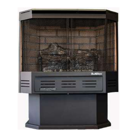
MAY BE INSTALLED IN A SOLID FUEL BURNING FIREPLACE, AS A
FREESTANDING FIREPLACE OR WITH AN OPTIONAL WOODEN SURROUND.
WARNING: If the information in this manual is not followed exactly, a fire or
explosion may result causing property damage, personal injury or loss of life.
Do not store or use gasoline or other flammable vapors and liquids in vicinity of this or any
other appliance.
WHAT TO DO IF YOU SMELL GAS
Do not try to light any appliance.
Do not touch any electrical switch; do not use any phone in your building.
Immediately call your gas supplier from a neighbor's phone. Follow gas supplier's instruc-
tions.
If you cannot reach your gas supplier, call the fire department.
Installation and service must be performed by a qualified installer, service agency or gas
supplier.
This is an unvented gas-fired heater. It uses air (oxygen) from room in which it is installed.
Provisions for adequate combustion and ventilation air must be provided. Refer to section "
Producing Adequate Air For Combustion And Ventilation" page 32.
This appliance may be installed in an aftermarket, permanently located, manufactured (mobile)
home, where not prohibited by local codes.
This appliance is only for use with the type of gas indicated on rating plate. This appliance is
not convertible for use with other gases.
INSTALLER: Leave this manual with appliance.
CONSUMER: Retain this manual for future reference.
MANUFACTURED BY NEW BUCK
CORPORATION
200 ETHAN ALLEN DRIVE, PO BOX 69
SPRUCE PINE, N.C. 28777
www.buckstove.com
MODEL 329
This appliance is intended for supplemental heating.
VENT-FREE
Revised October 2019
Advertisement
Table of Contents

Related Manuals for New Buck Corporation 329B


Summary of Contents for New Buck Corporation 329B
- Page 1 MODEL 329 MAY BE INSTALLED IN A SOLID FUEL BURNING FIREPLACE, AS A FREESTANDING FIREPLACE OR WITH AN OPTIONAL WOODEN SURROUND. VENT-FREE WARNING: If the information in this manual is not followed exactly, a fire or explosion may result causing property damage, personal injury or loss of life. Do not store or use gasoline or other flammable vapors and liquids in vicinity of this or any ...
-
Page 3: Table Of Contents
TABLE OF CONTENTS MODEL 329 SECTION I: Safety Information ....................1 SECTION II: Fireplace Preparation ..................... 4 Fireplace Clearances ........................5 Gas Connection ..........................5 Placement of Logs ........................6-7 Gas Pressure Check ........................8 Lighting Instructions - SIT Modulating Valve or -SIT Manual ............ 9 Lighting Instructions - SIT Millivolt Valve ................ -
Page 4: Section I: Safety Information
SECTION I SAFETY INFORMATION WARNINGS IMPORTANT: READ THIS OWNER’S MANUAL CAREFULLY AND COMPLETELY BEFORE TRYING TO ASSEMBLE, OPERATE OR SERVICE APPLIANCE. IMPROPER USE OF THESE LOGS CAN CAUSE SERIOUS INJURY OR DEATH FROM BURNS, FIRE, EXPLOSION AND CARBON MONOXIDE POISONING. NOTE: When burning any unit or appliance that combusts fuel for heat, such as ... - Page 5 5. If this heater is used with propane gas, do not place propane supply tank (s) inside any structure. 6. What To Do IF You Smell Gas: - Shut off gas supply. - Do not try to light any appliance. - Do not touch any electrical switch;...
- Page 6 21. All heater screens must be kept closed when operating gas logs. WARNING: Failure to keep primary air opening (s) of the burner (s) clean may result in soot and property damage. 23. Do not use this heater for burning trash or cooking. Never place matches, paper, garbage or any other material on top of logs or into flames.
-
Page 7: Section Ii: Fireplace Preparation
SECTION II FIREPLACE PREPARATION The fireplace needs to be prepared before installing heater. A. Turn off the gas supply to fireplace. WARNING: BEFORE INSTALLING IN A SOLID-FUEL BURNING FIREPLACE, CHIMNEY FLUE AND FIREBOX MUST BE CLEANED OF SOOT, CREOSOTE, ASHES AND LOOSE PAINT BY A QUALIFIED CHIMNEY CLEANER. -
Page 8: Fireplace Clearances
INSTALLATION AND CLEARANCES To ensure a safe installation into a masonry or factory built fireplace, following instructions must be carefully followed: (1) Sidewall Clearances: Clearance from side of fireplace opening to any adjacent combustible wall should not be less than: right side 7", left side 7". (2) Ceiling Clearances: The ceiling height should not be less than 24"... -
Page 9: Placement Of Logs
#POCR34LG-CR3329 CERAMIC LOG SET PLACEMENT, FOR MODEL 34 (1-R) (1-L) WARNING: Failure to position parts in accordance with these diagrams or failure to use only parts specifically approved with this heater may result in property damage or personal injury. WARNING: POSITIONING OF LOGS IS VERY CRITICAL (SEE DIAGRAM ABOVE). - Page 10 #POCRESBLG-E.S.B. LOG SET PLACEMENT FOR MODEL 329 “MILLIVOLT ONLY” WARNING: Failure to position parts in accordance with these diagrams or failure to use only parts specifi- cally approved with this heater may result in property damage or personal injury. WARNING: POSITIONING OF LOGS IS VERY CRITICAL (SEE DIAGRAM ABOVE).
-
Page 11: Gas Pressure Check
GAS PRESSURE CHECK Check the inlet pressure to burner to ensure that it is as shown in table below. NOTE: The pressure check point is located on right side of valve facing burner, for SIT Millivolt and left side for SIT Modulating. The appliance and its appliance main gas valve must be disconnected from gas supply piping system during any pressure testing of that system at test pressures in excess of 1/2 psi (3.5kPa). -
Page 12: Lighting Instructions - Sit Modulating Valve Or -Sit Manual
LIGHTING INSTRUCTION MODULATING OR MANUAL VALVE (SIT) FOR YOUR SAFETY READ BEFORE LIGHTING WARNING IF YOU DO NOT FOLLOW THESE INSTRUCTIONS EXACTLY, A FIRE OR EXPLOSION MAY RESULT CAUSING PROPERTY DAMAGE, PERSONAL INJURY OR LOSS OF LIFE. A. This appliance has a pilot which must be lighted by hand. When lighting pilot, follow these instructions exactly. - Page 13 LIGHTING INSTRUCTION 1. STOP! Read safety information on preceding page 13. 2. Make sure manual shutoff valve is fully closed. 3. Turn off all electrical power to appliance. 4. Open access panel door located at bottom front of appliance. 5. Turn control knob clockwise to full “OFF”...
- Page 14 REV. DATE DISCRIPTION APRVD DATE NEW RELEASE 11. Turn gas control knob counterclockwise to “ON” position. Continue to turn gas control knob counterclockwise to your desired setting. 12. Close access panel door. 13. Turn on all electrical power to appliance. 4-10-01 N.T.S.
- Page 15 THERMOSTAT CONTROL OPERATION The thermostat control on this heater differs from standard thermostats. Standard thermostats simply turn burner on and off. The thermostat used on this heater senses room temperature and adjusts amount of gas flow to burner. This will increase or decrease flame height.
-
Page 16: Lighting Instructions - Sit Millivolt Valve
OPERATING INSTRUCTIONS Before operating this appliance, proceed through following checklist. 1. Read and understand these instructions before operating this appliance. 2. Check that there are no gas leaks. If you smell gas do not attempt to light this appliance. 3. Verify that log placement is correct. LIGHTING INSTRUCTIONS SIT-MILLIVOLT VALVE FOR YOUR SAFETY READ BEFORE LIGHTING... - Page 17 LIGHTING INSTRUCTIONS 1. STOP! Read the safety information on pages 1 and 32. 2. Make sure manual shutoff valve is fully closed. If equipped with thermostat, set to lowest setting. 3. Turn off all electrical power to appliance. 4. Open access cover door located at the bottom of front of appliance. 5.
- Page 18 If pilot will not stay lit after several tries, turn gas control knob to “OFF” and call your service technician or gas supplier. 11. Turn control knob counterclockwise to “ON”. 12. If using unit without wall thermostat place Auto/Off/Manual switch into manual position. If using wall thermostat place Auto Off Manual Switch into auto position and place thermostat to a setting higher than room temperature.
- Page 19 MANUAL LIGHTING PROCEDURE 1. If pilot cannot be lit with piezo, it can be manually lit with use of a paper match and a lighter rod. 2. Open access panel door located at bottom front of appliance. 3. Place match in holder and light. With the left hand, turn control knob counterclockwise to “PILOT”position.
-
Page 20: Flame Check
FLAME CHECK A periodic check of flames should be made. The pilot flame should always be present when gas logs are in operation. Rear Flames: Flames at rear or at either side of top log should be very similar, yellow in color and should be about 3"... -
Page 21: Wiring Diagram
WIRING DIAGRAM THERMOSTAT JUMPER MOTOR JUMPER JUMPER WHITE GREEN BLACK RHEOSTAT BLACK POWER CORD Figure 9 WARNING: CHILDREN AND ADULTS SHOULD BE ALERTED TO HAZARDS OF HIGH SURFACE TEMPERATURES AND SHOULD STAY AWAY TO AVOID BURNS OR CLOTHING IGNITION. YOUNG CHILDREN SHOULD BE CAREFULLY SUPERVISED WHEN THEY ARE IN SAME ROOM WITH APPLIANCE WARNING:... -
Page 22: Room Blower Installation And Operation
WARNING: ELECTRICAL GROUNDING INSTRUCTION:THIS APPLIANCE IS EQUIPPED WITH A THREE- PRONG (GROUNDING) PLUG FOR YOUR PROTECTION AGAINST SHOCK HAZARD AND SHOULD BE PLUGGED DIRECTLY INTO A PROPERLY GROUNDED THREE-PRONG RECEPTACLE. NOTE: #PESBR084 Blower Motor Rating: 120 volts/60HZ/1.1 Amps. See Figure 9, page 18 for wiring diagram. NOTE: For convenience, allow licensed electrician to install properly grounded 3-plug receptacle near unit. -
Page 23: Section Iii: Solid Fuel Burning Fireplace Installation (Fp)
SECTION III INSTALLATION MODEL 329 (FP) IN SOLID FUEL BURNING FIREPLACES (1) Model 329 (FP) may be installed in a masonry fireplace. Minimum fireplace dimension must be 24" high, 29-1/2" wide, and 6" deep. (2) For minimum dimensions for sidewall and mantel, see Figure 11. (3) Center heater in fireplace opening. - Page 24 Set top (long) trim panel in place on top of unit. The panel should be flat against outside face of fireplace and standing vertically. Mark along lower edge of trim panel with a pencil to make reference line for mounting. (4) Slide the unit out of fireplace far enough to work behind trim panel reference lines with a screw gun.
-
Page 25: Section Iv: Freestanding Installation (Fs)
SECTION IV MODEL 329(FS) FREESTANDING INSTALLATION (1) Determine exact position of your gas heater. NOTE: Due to high temperatures, this heater should be located out of traffic areas and away from furniture and draperies. NOTE: For safe installation the minimum clearances must be met. See Figure 12. 0"... -
Page 26: Pedestal / Legs Installation
FREESTANDING PEDESTAL INSTALLATION (1) Lay the heater on its back (use a drop-cloth to protect back of heater and surface of your flooring). Place pedestal against bottom of heater. Center pedestal from left to right and from front to rear. Mark holes on angle on top of pedestal. -
Page 27: Section V: Alcove Installation
SECTION V MODEL 329 ALCOVE INSTALLATION CAUTION: READ ENTIRE MANUAL BEFORE INSTALLING HEATER (1) For clearances, see Figure 14. The minimum must be met. (2) For Installation and Gas Hookup Connection see Section II page 5. CAUTION: The installation must conform with local codes or in absence of local codes, with National Fuel Gas Code, ANSI Z223.1/NFPA54. -
Page 28: Section Vi: Wooden Surround Installation (Ws)
SECTION VI INSTALLATION OF MODEL 329 (WS) WITH OPTIONAL WOODEN SURROUND (KIT#PAKDFP34) See page 24, figure 10 for Clearances to Combustible Materials. (1) When choosing right location for your heater and mantel keep following in mind: NOTE: Due to high temperatures, this heater should be located out of traffic areas and away from furniture and draperies. - Page 29 (5) After mantel has been assembled, take metal strips out of box supplied with mantel. Position side strips on each side of your 329 with a maximum of 9 3/4" from back of stove to edge of your metal strip. Attach with self tapping screws. (6) Take top strip and screw it to top of your 329 overlapping your side panels on it.
-
Page 30: Section Vii: Installation-After Market Permanently Located Manufactured Home
SECTION VII INSTALLATION AFTER MARKET PERMANENTLY LOCATED MANUFACTURED HOME NOTE: See section VIII for “Producing Adequate Air For Combustion And Ventilation” See Page 28. THIS APPLIANCE MAY BE INSTALLED IN AN AFTERMARKET*, PERMANENTLY LOCATED, MANUFACTURE HOME, WHERE NOT PROHIBITED BY LOCAL CODES. *(After Market: Completion of sale, not for purpose of resale from manufacturer.) For mobile home installation instruction follow instructions provided in this manual completely... -
Page 31: Producing Adequate Air For Combustion And Ventilation
PRODUCING ADEQUATE AIR FOR COMBUSTION AND VENTILATION This section is for residential or permanently located manufactured home installation This heater shall not be installed in unusually tight construction or unconfined space unless pro- visions are adequate for combustion and ventilation air. NOTE: This heater shall not be installed in a room or space unless required volume of indoor combustion air is provided by method in National Fuel Gas Code, ANSIZ223.1/NFPA 54, In- ternational Fuel Gas Code or applicable codes. - Page 32 1. Determine the volume of space (length x width x height). Length x Width x Height =_________cu.ft.(volume of space) EXAMPLE: 20 ft.(Length) x 16 ft.(Width) x 8 ft.(ceiling Height)= 2560 cu. ft. (volume of space) If additional ventilation to adjoining room is supplied with grills or openings, add volume of these rooms to t total volume of space.
-
Page 33: Air For Combustion And Ventilation Inside Building
AIR FOR COMBUSTION AND VENTILATION INSIDE BUILDING This fresh air would come from an adjoining unconfined space. When venting to an adjoining space, you must provide two permanent openings: one within 12" of the ceiling and one within 12" of floor on wall connecting two spaces. -
Page 34: Air For Combustion And Ventilation Outdoors
WARNING THIS HEATER MUST HAVE ADEQUATE AMOUNT OF AIR FOR PROPER OPERATION. IF NOT, POOR FUEL COMBUSTION COULD RESULT. READ THE FOLLOWING INSTRUCTIONS TO ENSURE PROPER AMOUNT OF AIR FOR THIS AND OTHER FUEL-BURNING APPLIANCES IN YOUR HOME. AIR FOR COMBUSTION AND VENTILATION OUTDOORS Provide extra fresh air by using ventilation grills or ducts. -
Page 35: Important Safeguards
IMPORTANT SAFEGUARDS Although your gas logs are very realistic in appearance, it is not a real burning fireplace and must not be used for burning rejected material. To avoid irreparable damage to heater or personal injury, matches, paper, garbage or any other material must not be placed or thrown on top of Logs or into flames. -
Page 36: Troubleshooting
TROUBLESHOOTING WARNING TURN OFF AND UNPLUG HEATER AND LET COOL BEFORE SERVICING. ONLY A QUALIFIED SERVICE PERSON SHOULD SERVICE AND REPAIR HEATER. CAUTION NEVER USE A WIRE, NEEDLE OR SIMILAR OBJECT TO CLEAN ODS/PILOT. THIS CAN DAMAGE ODS/PILOT. OBSERVED POSSIBLE PROBLEM CAUSE SOLUTION... - Page 37 4. Air in gas lines when 4. Continue to hold down control installed knob. Repeat igniting operation until air is removed. 5. Depleted gas supply 5. Contact local propane gas company 6. ODS/Pilot is clogged 6. Clean ODS/Pilot or replace ODS/Pilot assembly 7.
- Page 38 OBSERVED POSSIBLE PROBLEM CAUSE SOLUTION Burner does not light after ODS/ 1. Burner orifice is clogged 1. Clean burner (see Cleaning Pilot is lit and Maintenance) or replace burner orifice 2. Inlet gas pressure is too low 2. Contact local propane gas company Delayed ignition of burner 1.
- Page 39 WARNING IF YOU SMELL GAS: * DO NOT TRY TO LIGHT APPLIANCE * DO NOT TOUCH ANY ELECTRICAL SWITCH; DO NOT USE ANY PHONE IN YOUR BUILDING * IMMEDIATELY CALL YOUR GAS SUPPLIER FROM A NEIGHBOR’S PHONE. FOLLOW GAS SUPPLIER’S INSTRUCTIONS. * IF YOU CANNOT REACH YOUR GAS SUPPLIER, CALL FIRE DEPARTMENT.
-
Page 40: Service And Repair Parts
A parts list with exploded view follows. Always include correct name, part number and model number of heater when ordering service parts. Please contact your local dealer or distributor when ordering . If one is not available, you may contact. NEW BUCK CORPORATION 200 ETHAN ALLEN DRIVE, PO. BOX 69 SPRUCE PINE, NC 28777... -
Page 41: Replacement Parts
REPLACEMENT PARTS SIT MODULATING OR SIT MANUAL MA343BA BASE (Picture on page 3) KEY# PART DESCRIPTION PART NUMBER 1. Pilot (NAT.) Copreci PE 2150053 - NAT 1. Pilot (LP) Copreci PE 2150054 - LP 2. Thermocouple (Copreci) PE TPT100 / 90 3a. - Page 42 SIT MODULATING OR SIT MANUAL MA343BA BASE Page 39...
- Page 43 REPLACEMENT PARTS SIT MILLIVOLT VALVE MA344BA BASE (Picture on page 41) KEY# PART DESCRIPTION PART NUMBER 1. 820 MV. S.I.T. Valve (LP) LP-PE 820636 1. 820 MV. S.I.T. Valve (NAT) NAT– PE 820638 2. Burner Tube PO DTBURN 3. O.D.S. Pilot O.P. Assembly (LP) PE 8404C 3.
- Page 44 SIT MILLIVOLT VALVE MA344BA BASE Page 41...
- Page 45 REPLACEMENT PARTS SIT MILLIVOLT VALVE MA344EBBA ESB BASE (Picture on page 43) A parts list with exploded view follows. Always include correct name, part number and model number of the heater when ordering service parts. KEY# PART DESCRIPTION PART NUMBER 1.
- Page 46 SIT MILLIVOLT VALVE ESB MA344EBBA BASE Page 43...
-
Page 47: Warranty
NEW BUCK CORPORATION We reserve rights to amend these specifications at any time without notice. The only warranty applicable is our standard written warranty. We offer no other warranty, expressed or implied. LIMITED WARRANTY VENT-FREE GAS LOG HEATER New Buck warrants this product to be free from defects in materials and components for two (2) years from date of first purchase, provided that product has been properly installed, operated and maintained in accordance with all applicable instructions. -
Page 48: Owner Registration
Number and Certified Installer’s number (if applicable) for warranty coverage to begin. NAME: ____________________________________________________ ADDRESS: _________________________________________________ CITY: _____________________________________________________ STATE: ______________________ ZIP: ________________________ CUSTOMER EMAIL:_________________________________________ MODEL #: FP-329B SERIAL #: ____________________________ DATE OF INSTALLATION: ___________________________________ INSTALLER’S NAME: _______________________________________ PURCHASED FROM: _______________________________________...
Need help?
Do you have a question about the 329B and is the answer not in the manual?
Questions and answers