Table of Contents
Advertisement
Quick Links
Advertisement
Chapters
Table of Contents

Subscribe to Our Youtube Channel
Related Manuals for Utax XC 9048


Summary of Contents for Utax XC 9048
- Page 1 XC 9048 INSTRUCTION HANDBOOK LARGE FORMAT SYSTEM...
- Page 2 Thank you for purchasing the Multi-Function Printer XC 9048. This USER'S GUIDE contains functional and operational explanations for the XC 9048. Please read this USER'S GUIDE carefully before using the Printer. Please keep this USER'S GUIDE for future reference. 1. When this product is installed in North America.
- Page 3 Safety Warnings The following warnings are very important in order to safely use this product. These notes are important in preventing danger to the operator or operation of the printer. The following symbols are found throughout the USER’S Manual and have the following meaning: WARNING This WARNING mark means that there is a possibility of death or serious injury if you ignore or do not follow the said instruction.
- Page 4 WARNING Ground the product with a correct ground source or you may be electrically shocked. 1. The Power source should be as follows: In the USA: 120V plus/minus10%, 50/60Hz, 15A or higher In Europe: 220-240V plus6% or minus10%, 50/60Hz, 10A or higher 2.
- Page 5 CAUTION Do not install the printer in a humidified room or a dusty room. Also, do not install the printer on an unstable floor as injuries may occur. 1. Unplug the printer before you move it. The power cord may be damaged and it may result in a fire or electric shock.
- Page 6 POWER CORD INSTRUCTION The installation of (or exchange to) a power plug which fits in the wall outlet of the installation location shall be conducted in accordance with the following: WARNING Select a power plug which meets the following criteria; - The plug has a voltage and current rating appropriate for the product’s rating marked on its name plate.
-
Page 7: Table Of Contents
Chapter 1 Before Use page 1. 1 Installation Requirements 1- 2 1. 2 Originals Prohibited from Duplication 1- 3 1. 3 Features 1- 4 1. 4 Specifications 1- 5 1. 5 Appearance 1- 7 1. 5. 1 Front view 1- 8 1. -
Page 8: Installation Requirements
The equipment must be leveled and the floor strength must be ample to sustain the weight of the equipment. 60cm or wider (When Tray is installed.) (Rear side) 45cm or 45cm or wider wider XC 9048 (Front side) 70cm or wider (1 Roll Deck) 90cm or wider (2 Roll Decks) Chapter 1 Before Use... -
Page 9: Originals Prohibited From Duplication
1. 2 Originals Prohibited from Duplication It is not necessarily allowed to copy every kind of original. You may be punished by the law if only you possess the copy of some kind of original. We recommend you to consider enough before you copy such original. [Originals prohibited from copying by the law] 1. -
Page 10: Features
1. 3 Features (1) XC 9048 Digital Printer is a Multi-Function Printer which is available for scan, copy and print. (2) The operation speed is 80mm/s (3.4ppm/E, 5.8ppm/D Landscape) (3) The maximum print width is 914mm (36 inches) wide, and the minimum one is 210 mm or 8.5”. -
Page 11: Specifications
1. 4 Specifications 1. 4. 1 General Subject Specification Model XC 9048 Configuration Console Power consumption 1,680 W (Including Scanner & Controller Unit) (Maximum) Power consumption 49.8 W (Low power mode) Acoustic noise Idling Max. 60db Printing Max. 65db Impulse sound Max. - Page 12 1. 4. 2 Printer part Subject Specification Printing method LED Array Electro photography Photoreceptor Organic Photoconductive Drum Print speed 80 mm per second (Metric) 3.3 ppm/A0 5.6 ppm/A1 Landscape (Inch) 3.4 ppm/E 5.8 ppm/D Landscape Print head LED Array Resolution of print head 600 dpi x 600 dpi Print width Maximum...
- Page 13 1. 4. 3 Scanner part Subject Specification Scanning method Contact Image Sensor (CIS) (5 pieces of A4 sized CIS) Light source LED (R/G/B) Setting of original Face up Starting point of scan Center Scan width Max: 914.4mm Min : 279.4mm Scan length Max: 6,000mm (Including the margin area)
-
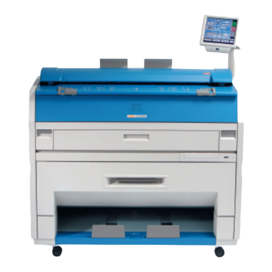
Page 14: Appearance
1. 5. 1 Front view Name Function Main Switch You can turn on/off the XC 9048. Original Guides Feed the original under the Scanner Unit along the Original Guides. User Interface This is a Touch Screen, and many kinds of user operation are available. -
Page 15: Rear View
Exit Cover Open the Exit Cover when you remove the paper misfed inside the Fuser Unit. LAN Port Connect the LAN Cable to connect the XC 9048 to the network. (Do not connect a telephone line) Dehumidify Heater Switch Turn on the Dehumidify Heater with this switch when you (Optional in the US) would like to dry the paper in the humid season. -
Page 16: Specifications For The Scan Original
1. 6 Specifications for the Scan Original A scan original must satisfy the following specifications. Thickness 0.05 mm to 1.6 mm Width 279.4 mm to 914.4 mm Length 210 mm to 3,600 mm Do not scan the following kinds of originals. The original or the scanner may damage. Stuck with paste Paste Torn... - Page 17 Not square K I P K I P Metal or fabric material Metal Fabric K I P K I P Rough surface (Carbon paper for example) Rough surface Clipped or stapled Clipped Stapled K I P K I P 1-11 Chapter 1 Before Use...
- Page 18 The following kinds of originals can be read with using a carrier sheet. Image quality or the reliability of paper feeding for them is not guaranteed. Patched Punched 1-12 Chapter 1 Before Use...
-
Page 19: Specifications For The Printing Paper
1. 7 Specifications for the Printing Paper 1. 7. 1 Papers not available to use Do not use the following kinds of printing paper. Doing so may damage the print engine. Excessively curled (a diameter of 50 mm or less) Folded Creased Torn... -
Page 20: Keeping The Paper In The Custody
Pre-printed Extremely slippery Extremely sticky Extremely thin and soft OHP Film CAUTION Do not use the paper with staple, or do not use such conductive paper as aluminium foil and carbon paper. The above may result in the danger of fire. NOTE (1) Print image may become light if printed on a rough surface of the paper. -
Page 21: Treatment Against Environmental Condition
High NOTE (1) XC 9048 is equipped with the Dehumidify Heater (optional for the US). Using it in high humidity environment (65% or higher) is recommended. Refer to [2. 9 Dehumidifying Roll Media] on page 2-18. - Page 22 Chapter 2 Basic Operation page 2. 1 Turning on XC 9048 2- 2 2. 2 Turning off XC 9048 2- 4 2. 3 Roll Media Replacement 2- 5 2. 4 Toner Cartridge Installation 2-10 2. 5 Cut Sheet Media Placement 2-14 2.
-
Page 23: Turning On Xc 9048
2. 1 Turning on XC 9048 1. Ensure that the XC 9048 is plugged into a dedicated wall outlet. WARNING (1) Do not handle the Power Plug with wet hands, or you may receive an electrical shock. (2) Make sure to earth the machine for safety. - Page 24 A Ready Indicator on Copy Mode Screen will flash during warming up. Ready Indicator Note: The screen is shown with available options. 4. When the Ready Indicator stops flashing, the XC 9048 is ready for operation. You can make a copy, scan (optional) or print (optional). Chapter 2 Basic Operation...
-
Page 25: Turning Off Xc 9048
” side. CAUTION The XC 9048 print engine and UI appear to be shut down when you turn off XC 9048. However, the controller PC embedded inside the XC 9048 is still operating and will shutdown in approximately two minutes after Power Switch operation. -
Page 26: Roll Media Replacement
2. 3 Roll Media Replacement NOTE (1) A paper mis-feed tends to occur just before out of a roll paper. (2) A tracing roll paper is recommended to be loaded to Roll Deck 1 (front). Reference This section describes how to install a roll media to Roll Deck 1. The same procedure is applied to Roll Deck 2, unless otherwise noted. - Page 27 4. Insert each Flange (4) into both ends of the roll media core to be installed. NOTE (1) Fully insert Flange into the roll media core so that the inside rim of Flange evenly touches the side face of the roll media. Inside Rim Inside Rim Correct: Fully inserted...
- Page 28 5. Push both the levers (3) down in either way. Position them flat against Flange to secure the roll media. 6. Lift the roll media by holding both Flanges. Lower Flanges onto Slide Guides (5) in Roll Deck. NOTE (1) Note the rewinding direction. Rear: Deck back Rear: Deck back Front: to Guide Plate...
- Page 29 NOTE (2) The outside rim (7) of Flange should meet the black triangle (8) marked on Slide Guide. Otherwise the roll media may fall in Roll Deck or result in an incorrect media feeding. Correct Wrong 7. Insert the leading edge of the roll media under Guide Plate (9) until it touches the feeding roller. Rotate Feed Knob (10) clockwise so that the feeding rollers catch the leading edge.
- Page 30 8. Hold the green grip (12: on the middle of Guide Plate) and turn Guide Plate outside. With holding, rotate Feed Knob (10) again so that the leading edge comes out in 100 mm. Leading edge 9. Slide the green Cutter Knob (13) fully from one side to the other to make a new straight edge. Remove the cut portion.
-
Page 31: Toner Cartridge Installation
2. 4 Toner Cartridge Installation 1. Open the Toner Hatch (1). 2. Slide the green Lever (2) to the right to unlock the Toner Cartridge. (Lever (2) is held automatically.) 2-10 Chapter 2 Basic Operation... - Page 32 3. Pressing down the Cartridge Lock Lever (3), turn the body (4) of cartridge to the arrow direction until it stops. (You can close the toner supply hole of the cartridge firmly by this treatment.) NOTE The toner may drop from the toner supply hole, and it may scattered into the machine or on the floor if you remove the Toner Cartridge without closing the toner supply hole (5).
- Page 33 5. Shake the new Toner Cartridge several times left and right to make the toner smooth. 6. Pressing down the Cartridge Lock Lever (3), fit the pin (6) on the left side of cartridge to the groove (7) on the machine side. NOTE Please confirm that the Cartridge Lock Lever (3) firmly locks the Toner Cartridge at the correct position.
- Page 34 7. Turn the body (4) of the cartridge in one revolution to the arrow direction to open the toner supply hole. Confirm that the projection (8) if fitted into the notch (9). NOTE It is not necessary to lock the cartridge with the Lever (2). Lever (2) will engage on its own after closing the Toner Hatch.
-
Page 35: Cut Sheet Media Placement
2. 5 Cut Sheet Media Placement 1. Open the Bypass Feeder (1). 2. There are several size markings on the table of Bypass Feeder which indicate possible feed positions. Place the cut sheet paper on the table between its concerning size markings then insert it into the Bypass Feeder. -
Page 36: Copying
When the leading edge touches the original feeding roller, the machine automatically carries and sets the original at the proper position. 3. The XC 9048 will start the print process. NOTE The scanner unit does not accept originals automatically during Sleep Mode. Touch any area in the touch screen and then insert an original. -
Page 37: Emergency Stop Of Scan Or Copy
2. 7 Emergency Stop of Scan or Copy If necessary, press the Emergency Stop Button (1) on the Scanner Unit to immediately stop the original while making a copy or scan. Pressing the button stops the current reading a document immediately. The current printing is stopped as well and is ejected. -
Page 38: Canceling Sleep Mode
2. 8 Canceling Sleep Mode The XC 9048 has two Sleep Modes to reduce the power consumption. The XC 9048 will enter Sleep Mode after a certain period of inactivity. In the default setting; • Warm Sleep Mode will start after a 15 minute of inactivity in order to reduce the power supply for Fuser Unit. -
Page 39: Dehumidifying Roll Media
You may be able to fix the above kinds of problem. NOTE XC 9048 is equipped with the Dehumidify Heater (optional for the US) If needed, contact the service personnel for detail. To turn on the Dehumidify Heater, press the H side of the Dehumidify Heater Switch on the rear. - Page 40 Chapter 3 Error Correction page 3. 1 Operator Call Errors 3- 2 3. 1. 1 Paper mis-feed error 3- 2 3. 1. 1. 1 Deck Jam / Feeding Jam 3- 3 3. 1. 1. 2 Manual Jam 3- 5 3. 1. 1. 3 Reg.
-
Page 41: Operator Call Errors
3. 1 Operator Call Errors 3. 1. 1 Paper mis-feed errors NOTE (1) Take care not to get paper cuts on your hand. (2) Take off your ring, bracelet or watch when clearing paper jam. If they touch to internal components, it may result in a burn, an electric shock or damage to components. -
Page 42: Deck Jam / Feeding Jam
3. 1. 1. 1 Deck Jam / Feeding Jam Either of “Deck is jam” or “Feeding Jam” will be indicated when the roll paper is mis-fed in the Roll Deck. 1. Open the Roll Deck, and then rewind the roll paper. 2. - Page 43 3. When the feeding rollers catch the paper, turn the middle of the Guide Plate 6 (4) outside. Rotate the Paper Feeding Knob (2) again until the leading edge comes out in 100 millimetres. Leading edge 4. Slide the green Cutter Knob (5) one side to another completely to make a new straight edge. Remove the cut portion.
-
Page 44: Manual Jam
3. 1. 1. 2 Manual Jam 1. Pull up the Engine Unit Open Levers (1) to open the Engine Unit. NOTE Do not open the Engine Unit when the Scanner Unit is opened. If the Scanner Unit is opened, it will hit the bottom of User Interface. 2. -
Page 45: Reg. Jam / Internal Jam
3. 1. 1. 3 Reg. Jam / Internal Jam 1. Pull up the Engine Unit Open Levers (1) to open the Engine Unit. NOTE Do not open the Engine Unit when the Scanner Unit is opened. If the Scanner Unit is opened, it will hit the bottom of User Interface. 2. -
Page 46: Fuser Jam
3. 1. 1. 4 Fuser Jam 1. Pull up the Engine Unit Open Levers (1) to open the Engine Unit. NOTE Do not open the Engine Unit when the Scanner Unit is opened. If the Scanner Unit is opened, it will hit the bottom of User Interface. 2. -
Page 47: Accessory Jam
4. Open the Exit Cover (2). 5. Remove the jammed paper pulling to the rear side. WARNING There are extremely hot parts inside the Exit Cover. Do not touch any parts in the Heater Unit, or you will be burnt. Also be careful not to get burnt when you touch the printing paper as it may be very hot. -
Page 48: Original Jam
3. 1. 1. 6 Original Jam 1. Open the Scanner Unit pulling up the Levers (1), and then remove the original. 2. Gently press Scanner Unit down and firmly close it. NOTE Press down Scanner Unit on both the sides to close it. Do not close it by pressing only one side down. -
Page 49: Others
Others 3. 1. 2. 1 Initial state This message is indicated when the XC 9048 is turned on for the first time. NOTE You will not find this message because every machine has been turned on at least once before shipment. -
Page 50: Cutter Set Ng
3. 1. 2. 5 Cutter Set NG This message is indicated when the Cutter Knob is not located at the correct position. Open the Roll Deck, and slide the Cutter Knob fully to the left or right to align the Cutter Knob with the end of the railing. -
Page 51: Service Call Errors
If any of the above errors appear: 1. Turn off XC 9048, and turn it on after an interval of 30 seconds or more. 2. If the same error code appears, turn off XC 9048, and then unplug the printer from the wall outlet after an interval of two minutes for shutdown. - Page 52 Chapter 4 Maintenance page 4. 1 Cleaning 4- 2 4. 1. 1 Scanner Unit 4- 2 4. 1. 2 Print Engine 4- 4 4. 1. 3 Touch Screen 4- 6 Chapter 4 Maintenance...
-
Page 53: Cleaning
Clean each Scan Glass, Feeding Rollers and Guide Plates once per a week, as the scan/copy image may become defective if these parts are dirty. 1. Turn off XC 9048. 2. Open the Scanner Unit pulling up the Levers (1). - Page 54 4. Wipe both the Feed Rollers (4) and the inside surface with a soft dry cloth. 5. Gently press Scanner Unit down and firmly close it. NOTE Press down Scanner Unit on both side to close it. Do not close it by pressing only one side down. Chapter 4 Maintenance...
-
Page 55: Print Engine
Clean each Guide Film and Guide Plate once per a week, as the toner or paper dust may accumulates on such part which may result in a defective print image. 1. Turn off XC 9048. 2. Open the Engine Unit pulling up the Engine Unit Open Levers (1). - Page 56 NOTE (1) There is a Photoconductive Drum (large green cylinder) in the machine, which is right above the Guide Plate. You will have to replace the Drum if it is damaged, as it is a very important part in creating the print image. Please take care of the following matters when you make cleaning.
-
Page 57: Touch Screen
4. 1. 3 Touch Screen Clean the Touch Screen once a week. 1. Wipe the Touch Screen with a dry cloth. NOTE Do not use water, alcohol, organic solvent and glass cleaner for the cleaning. Chapter 4 Maintenance... - Page 59 UTAX GmbH, Ohechaussee 235, 22848 Norderstedt, Germany...
Need help?
Do you have a question about the XC 9048 and is the answer not in the manual?
Questions and answers