Advertisement
Introduction
This manual is intended to familiarize users with the safe operation and maintenance procedures for the Model 600LS Test Set.
Please read this entire manual before operating the tool and keep this manual available to all personnel. Replacement manuals are available upon request at no extra charge.
Safety
Safety is essential in the use and maintenance of Tempo tools and equipment. This instruction manual and any markings on the tool provide information for avoiding hazards and unsafe practices related to the use of this tool. Observe all of the safety information provided.
Description
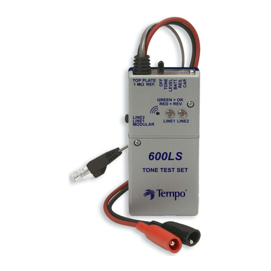
The 600LS test set is housed in a grey and blue plastic case. Red and black test leads are provided, which are equipped with alligator clips and are permanently attached to the set. A four conductor modular plug and cord, plus two light emitting diodes (LEDs), provide a modular polarity test. A six position slide switch controls the modes of operation, and there is a three position slide switch for testing each line at the modular plug.
The tone, level, resistance and capacitance features are powered by one internal 9 volt battery. The addition of a second 9 volt battery increases talk battery supply over original designs. (See Fig. 13) The polarity test feature is line powered.
The 600LS test set provides the following features:
-
Tone
A two tone audio trace signal is used to identify cable pairs, drop wires and I/O wire pairs and for proving continuity of single conductors. The signal will also radiate with sufficient strength to be detected by a lineman's test set or an inductive amplifier. -
Level
This position is for checking line condition. No tone indicates a dead line or reversed polarity (0V-2V). An alternating (Hi-lo) tone indicates an active line off-hook (2V-28V).A steady tone indicates an active line not in use (28V-48V). -
Battery
Approximately 18 volts of talk battery is provided for two way communication, when two batteries are installed. -
Resistance
This feature provides an audible indication of various levels of circuit and insulation resistance. With the test leads connected to a low resistance circuit, a rapid series of beeps is produced by the test set. As the resistance of the circuit being tested increases, the time interval between beeps also increases. -
Capacitance
An audible indication of circuit capacitance is produced by the internal speaker. This test can be used to indicate the amount of capacitance on a line.- PolarityTest
Two 2-color LEDs provide visible indication of central office battery polarity present at a modular connector. Ringing current is indicated by a red/green flickering LED (appears yellow). (See Polarity Testing) - Modular Test Selector Switch
The above tests, except polarity, may be performed on Line 1 or Line 2 through the modular cord.(See Modular Line Testing)
- PolarityTest
-
Calibration
In resistance mode, an internal resistor valued at 1meg ohm is provided for comparison to the fault resistance of the circuit or facility being tested.
Operation
All tests and operations outlined in the following paragraphs are to be conducted with central office battery and any other source of electrical current disconnected from the facilities under test. This does not apply to level and line polarity tests.
Battery Check and Operational Test
To perform a battery check and operation test, place the slide switch in the "capacitance" position. An audio tone should be heard at the speaker opening indicating a good battery. If the audio tone is not heard, short the test leads together and place the slide switch in the "resistance" position. This should produce a rapid series of beeps from the speaker. If no beeps are heard, replace the batteries as outlined in the Maintenance Section and repeat.
A test set which fails to operate in any one of the modes after a new battery has been installed should be replaced.
Calibration
With the slide switch in the "resistance" position, touch the clip of the red test lead to the top plate or screw head next to the slide switch opening. This places a 1 megohm resistance on the test set leads through an internal resistor. The set should then produce a series of Fig. 2 beeps approximately one per second. This beep rate will subsequently be referred to as the "calibration rate."This rate will vary between test sets due to the component differences and battery condition.(See Fig.2)

A circuit can be considered to be clear of insulation faults if when tested with the resistance feature of the 600LS test set, it produces a series of beeps at a rate equal to or slower than the beep rate of 1 beep every 4 seconds, approximately 4 megohms.
Tone Operation
The "tone" position is used to identify pairs of conductors and to prove continuity. The dual tone trace signal is detected with a standard telephone set or a lineman's test set with the talk-monitor switch in the monitor position. (See Fig.3)

Pair identification can be determined as follows: Before an attempt is made to identify a pair of conductors, the pair should first be tested for shorts and grounds. Either of these conditions will attenuate (lower) the signal and produce false indications. Proceed as outlined in the Capacitance Section to ensure that the pair is "clear".
After the pair has been "cleared", place the slide switch in the "tone" position and connect the test leads to one end of the line under test and a lineman's test set to the other end of the line under test. A pair with an "open"conductor will produce a low tone similar to a "split"pair.
Proving Continuity
To prove continuity of a single conductor, proceed as follows: Place slide switch on the 600LS test set in the "tone"position. Connect one test lead from the 600LS test set to one lead of the lineman's test set to provide a "series" connection. Connect the remaining test lead from the 600LS to one end of the conductor being tested. Use the remaining lead on the lineman's test set as a "probe" and touch it to the other end of the conductor while listening for the tone to be produced in the receiver of the lineman's test set. (See Fig.4)

Continuity can also be proven by using the "resistance" feature of the 600LS test set. This is done by proving a relative lack of resistance in the conductor being tested. To do so, place the slide switch in the "resistance" position and connect one test lead to one end of the conduct or to be tested.(See Fig.5)


Documents / ResourcesDownload manual
Here you can download full pdf version of manual, it may contain additional safety instructions, warranty information, FCC rules, etc.
Advertisement


Need help?
Do you have a question about the 600LS and is the answer not in the manual?
Questions and answers