Table of Contents

Related Manuals for Tempo Fitness FSP200


Summary of Contents for Tempo Fitness FSP200
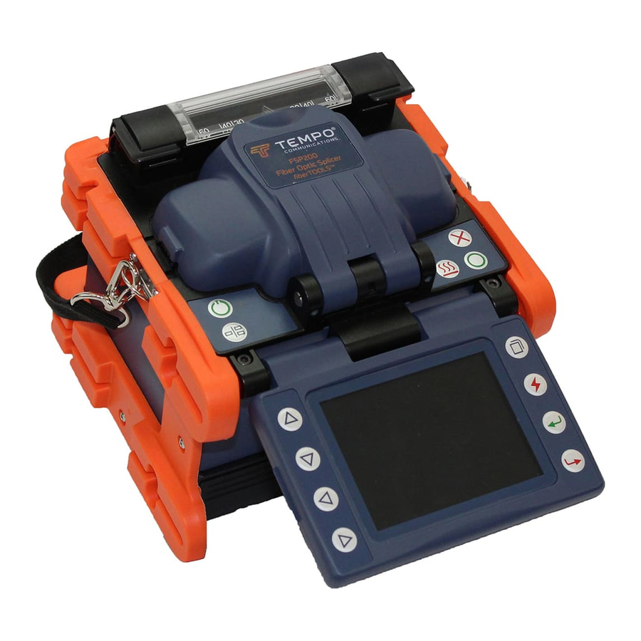
- Page 1 INSTRUCTION MANUAL FSP200 Optical Fiber Fusion Splicer Read and understand all of the instructions and safety information in this manual before operating or servicing this tool. 52063481 REV 6 © 2019 Tempo Communications Inc. 01/20...
-
Page 2: Table Of Contents
Splice Set ..........................25 Data Save ..........................26 Set ............................27 Section 4. Specifications Section 5. Troubleshooting Appendix A. FSP200 Fusion Splicer Cleaning Appendix B. Practice Splicing Appendix C. Tempo Communications Splice-on Connectors Tempo Communications Inc. 1390 Aspen Way • Vista, CA 92081 USA • 800-642-2155... -
Page 3: Preface
A fusing arc is applied, which then provides the lowest loss fusion splice. The FSP200 with PAS technology is designed for splicing many types of optical fibers. It is small in size and lightweight, making it suitable for any operating environment. -
Page 4: Important Safety Information
FSP200 Important Safety Information General Use this unit for the manufacturer’s intended purpose only, as described in this manual. Any other use can impair the protection provided by the unit. Do not use the splicer on live fibers. Environmental Conditions This tool is designed to operate at a maximum relative humidity of 95% and at altitudes up to 5000 m (16,400 ft). - Page 5 FSP200 Important Safety Information (cont’d) Electric shock hazard: Contact with live circuits could result in severe injury or death. Wear eye protection when using this tool. Fiber fragments can be extremely dangerous if they come into contacts with eyes or skin or are ingested.
- Page 6 FSP200 Important Safety Information (cont’d) Electric shock hazard: Use only proper power source. • Check AC power source before use. Proper AC power source is 100–240 VAC, 50–60 Hz. Proper DC power source is 10–12 VDC. Improper AC or DC power source could cause fuming, electric shock, or equipment damage.
- Page 7 FSP200 Important Safety Information (cont’d) Battery safety: • Do not allow anything to contact the battery terminals. • Do not immerse batteries in liquid. Liquid may create a short circuit and damage the battery. If batteries are immersed, contact your service center for proper handling.
- Page 8 FSP200 Important Safety Information (cont’d) • Do not use any chemical other than pure alcohol (99% or greater) to clean the objective lens, V-groove, LCD monitor, etc. Use of other chemicals may cause blurring, discoloration, damage, or deterioration. • This tool requires no lubrication. Oil or grease may degrade the splicing performance and damage the splicer.
-
Page 9: Section 1. Identification
FSP200 Description of Products Description of Products Section 1. Identification 2. Description and Function of Splicer 2. Description and Function of Splicer Front Side of OFS-95 Components of Splicer Front Side of OFS-95 Wind Protector Wind Protector Power Unit Dock ... - Page 10 FSP200 Description of Products Top View ➢ Top Side of OFS-95 ➢ Keypad of OFS-95 Tempo Communications Inc. 1390 Aspen Way • Vista, CA 92081 USA • 800-642-2155...
-
Page 11: Section 2. Operation Setup
Setup Installing Battery in Splicer The FSP200 can be powered by an external power adapter and battery. Inserting the Battery Remove the protective cover from the battery contacts. Insert the battery into the battery compartment until it clicks into place. -
Page 12: Splice Mode
FSP200 Turning Splicer ON Press and hold until the LED on the keypad turns ON (green color). The “Ready” screen is displayed after all the motors reset to their initial positions. The power source type is automatically identified. If the battery is used, the remaining battery capacity is displayed. -
Page 13: Fiber Preparation
FSP200 Fiber Preparation Placing Protection Sleeve over Fiber Place the protection sleeve over the fiber. Clean optical fiber with alcohol-soaked gauze or lint-free tissue approximately 100 mm (4 in) from the tip. Note: Splice-on connectors are pre-cleaved. Do not attempt to clean the fiber on the splice-on connector. Follow the instructions supplied with the splice-on connectors. -
Page 14: Splicing Procedure
Splicing Procedure To ensure a good splice, the optical fiber is observed with the image processing system equipped in the FSP200. However, in some cases the image processing system cannot detect a faulty splice. Visual inspection with the monitor is often necessary for better splicing yield. -
Page 15: Heating Protection Sleeve
FSP200 Notes: • Splice point sometimes looks a bit fatter than other parts. This is considered a normal splice and does not affect splice loss. • To change threshold for estimated splice loss or cleave angle, refer to “Splice Mode” in this manual for details. -
Page 16: Cooling Tray
Place the splice into the cooling tray on the back of the FSP200 splicer. Splice-on Connectors The FSP200 uses the Tempo Communications version of splice-on connectors. The FSP200 currently supports SC, LC, FC, and ST versions (both PC and APC finish, where applicable). -
Page 17: Button Functions
Starts splicing work Switches between X, Y and X/Y views Appendixes Refer to the following appendixes at the end of this manual for additional operating information: • Appendix A—FSP200 Fusion Splicer Cleaning • Appendix B—Practice Splicing • Appendix C—Tempo Communications Splice-on Connectors Tempo Communications Inc. -
Page 18: Section 3. Menu Operation
FSP200 Section 3. Menu Operation Press to enter the splicer menu. There are six main menus: Splice Mode Menu (S–Mode) Heater Mode Menu (H–Mode) Maintenance Splice Set Data Save Explanation of Splice Modes Mode No. Splice Mode Description For splicing in most cases; the splicer will automatically adjust splice parameters according to fiber type. - Page 19 FSP200 Explanation of Splice Modes (cont’d) For splicing standard single-mode fiber (ITU-T G652). The MFD is 9 to 10 µm at wavelength of 1310 nm. User can edit all parameters of this splice mode such as prefuse power, prefuse time, arc 6...
- Page 20 FSP200 (1) Select Splice Mode Select “S–Mode” to access the available splicing modes. Use the arrow keys to highlight the desired splicing mode. Then press OK to confirm. Select an appropriate splice mode for the type of fiber to be spliced, and use the arrow keys to select the splice mode. Then press OK to confirm.
- Page 21 FSP200 Note: In AUTO mode, certain parameters cannot be changed. • Fiber Type • Mode title 1 • Mode title 2 • Cleave limit • Loss limit • ARC1 power • ARC1 time • Cleaning ARC • Rearc time Parameter Description Arc2 Power In SM/DS/MM/NZ/AUTO modes the arc power is fixed at 40 bits.
-
Page 22: Heater Mode Menu (H-Mode)
FSP200 Summary of electrode activation Cleaning Arc Prefuse Time Arc1 Time Arc2 Time Rearc Time Prefuse Power Arc1 Power Arc2 Power Arc2 ON Time Arc2 OFF Time Note: Not all settings are available in the AUTO modes. This is a general guideline for the user to control the fusion settings. Every type of fiber has its own characteristics and properties that may require the manual setting of these parameters. - Page 23 FSP200 (2) Edit Heater Mode Tube-heating conditions stored in heater mode can be edited or changed. Editable parameters include Heat Time and Heat Temp (heating temperature). Heat Time will automatically adjust according to atmospheric conditions, e.g., ambient temperature. The actual Heat Time may vary from set Heat Time.
-
Page 24: Maintenance
Repeat steps 1–4 until “arc adjust OK” displays on splicer screen. Cleaning the Electrodes It may be necessary to clean the electrodes if the arc calibration fails or if the FSP200 is not splicing properly. 1. Turn splicer off. Remove battery and unplug from AC power. -
Page 25: Splice Set
the technician that there is a windshield or motor failure. • Align: The technician can set the FSP200 for full core alignment mode or clad alignment mode. • ECF: Enabling the ECF will allow the FSP200 to automatically adjust slightly mis-aligned fibers. -
Page 26: Data Save
This case often results in lower loss than case (c). Data Save The FSP200 stores up to 5000 splicing results. Splice Memory The Splice Memory function allows the user to display, export, and clear splice memory. Use arrow keys to select “Splice Memory”... -
Page 27: Set
• Software Version: Diplays the software version of the splicer. • Serial Number: Displays the fusion splicer serial number. The FSP200 can make and save up to 100 screen shots. To make a screen shot: 1. Press and hold the Menu key. 2. Press Enter to confirm. - Page 28 Password Provides the technician the opportunity to create a password to prevent the FSP200 from being used by unauthorized users. The fusion password will allow the splicer to be accessed but a splice can not be made without the password. The fusion limit password will allow a preset number of splices to be made before access will be denied.
-
Page 29: Section 4. Specifications
FSP200 Section 4. Specifications Applicable Fibers SM (G.652); MM (G.651); DS (G.653); NZDS (G.655); BIF (G.657); EDF Fiber Cleaved Length 10mm Cladding Diameter 80-150μm Coating Diameter 100-1000μm Fiber Count Single Fiber Aligning Method Core alignment Splice Loss (Typical) 0.02 dB (SM); 0.01 dB (MM); 0.04 dB (DS); 0.04 dB (NZDS & BIF) -
Page 30: Section 5. Troubleshooting
FSP200 Section 5. Troubleshooting High Splice Loss Cause and Remedy Symptom Cause Remedy Core axial offset Dust on V-groove or fiber clamp chip. Clean V-groove and fiber clamp chip. Core angle Dust on V-groove or fiber clamp chip Clean V-groove and fiber. Check damaged. - Page 31 Note: A vertical line sometimes appears at the spice point when MM fibers or dissimilar fibers (different diameters) are spliced. This does not affect splice quality, such as splice loss or tensile strength. Note: If the user is getting high splice losses, make sure that the FSP200 is not in Splice Mode #10, which is used to make attenuator splices.
- Page 32 FSP200 Error Messages Error Message Reason Solution Left/Right/L-R fiber set too • The fiber end-face is placed on the • Confirm the setting position of the stripped close! electrode centerline, or beyond it. fiber end on the fiber cleaver. Check the cleave •...
- Page 33 V-grooves are dirty. Clean V-grooves. LR_FIBER_DIRTY V-grooves are damaged. V-grooves need to be factory replaced. Fiber presser foot is dirty. Clean presser foot of FSP200. Fiber adapters are dirty. Clean fiber adapters. Mirrors are dirty. Clean mirrors . Lenses are dirty.
- Page 34 FSP200 If High Estimated Loss Reason Solution Insufficient fiber cleaning. Dust or dirt on the fiber surface results in bad splice loss and low tensile strength. • Clean the fiber surface sufficiently. • Do not clean the fiber after cleaving to prevent dust on the fiber end-face.
-
Page 35: Appendix A. Fsp200 Fusion Splicer Cleaning
FSP200 Appendix A. FSP200 Fusion Splicer Cleaning Precautions When Cleaning FSP200 • Turn off splicer. • Use only lint-free cotton swabs. • Use only 99% pure isopropyl alcohol or an approved substitute. • Do not touch the electrodes. • Never use compressed air. • Use the cleaning brush only to clean debris from general working area, never on the lenses, or V-grooves. - Page 36 FSP200 Cleaning Objective Lenses (recommended weekly) Refer to Figure 3. If the surfaces of the objective lenses become dirty, normal observation of the core position may be incorrect, resulting in higher splice loss or poor splicer operation. Therefore, clean both of them at regular intervals. Otherwise, dirt may accumulate and become impossible to remove.
- Page 37 FSP200 area of the fiber adapters. Cleaning Fiber Cleaver (recommended daily) Refer to Figure 4. If the circular blade or clamp pads of the fiber cleaver become contaminated, the cleaving quality could degrade. This may lead to fiber surface or end-face contamination, resulting in higher splice loss. Clean the circular cleaving blade and clamp pads with a lint-free cotton swab soaked with isopropyl alcohol.
-
Page 38: Appendix B. Practice Splicing
Refer to the contents of this instruction manual for the FSP200 and FCL200. • Clean all connectors before making a connection. It is highly recommended that new FSP200 users use the AUTO mode splicing profile until they have become proficient at splicing. Checking the Splice Quality of the FSP200 The user should practice splicing with the type of fiber that they will use in their installation before attempting to splice fibers in those installations. -
Page 39: Appendix C. Tempo Communications Splice-On Connectors
Slide the 900 μm strain relief boot and then the 27 mm mini splice protective sleeve over the 900 μm field fiber. Use the FCL200 to cleave the field fiber. Insert the fiber adapter with the cleaved fiber into the left-hand side of the FSP200 fusion splicer. Make sure to butt the 900 μm buffer up to the edge of the fiber adapter. - Page 40 FSP200 5. Insert the holder into the right-hand side of the splicer (Figure 6), making sure that the fiber stub lays properly into the V-groove block of the splicer. You may use the fiber positioning tool to help align the fiber in the V-groove. The fiber for FC and ST splice-on connectors must have the fiber laying in the end of the fiber groove in the V-groove.
- Page 41 Limited Warranty Tempo Communications Inc. warrants to the original purchaser of these goods for use that these products will be free from defects in workmanship and material for three year, excepting normal wear and abuse. For all Test instrument repairs, you must first request a Return Authorization Number by contacting our Customer Service department at: toll free in the US and Canada 800-642-2155 Telephone +1 760 510-0558.
Need help?
Do you have a question about the FSP200 and is the answer not in the manual?
Questions and answers