Table of Contents
Advertisement
Quick Links
CONTENTS
INTRODUCTION....................................................1
FEATURES............................................................. 1
SPECIFICATIONS..................................................2
EXPLANATION OF FEATURES...........................3-5
INSTALLATION.................................................... 6
DIAGRAM OF RX GAIN....................................... 7
B-24-G OPTIONAL ADAPTORS........................... 8-9
PRECAUTIONS...................................................... 10-11
CONNECTION DIAGRAM.....................................12
B-24-G BOOSTER AMP. BLOCK CIRCUIT..........13
WARRANTY...........................................................14
Advertisement
Table of Contents

Related Manuals for Mirage B-24-G


Summary of Contents for Mirage B-24-G
-
Page 1: Table Of Contents
CONTENTS INTRODUCTION............1 FEATURES............. 1 SPECIFICATIONS..........2 EXPLANATION OF FEATURES......3-5 INSTALLATION............ 6 DIAGRAM OF RX GAIN........7 B-24-G OPTIONAL ADAPTORS......8-9 PRECAUTIONS............10-11 CONNECTION DIAGRAM........12 B-24-G BOOSTER AMP. BLOCK CIRCUIT..13 WARRANTY............14... -
Page 2: Introduction
INTRODUCTION The B-24-G is a VHF band high power linear amplifier designed for the 144 MHz band. It has a maximum output power of 50W. With a combination of built-in low noise GaAsFET receive pre-amp, the B-24-G enables you to enjoy a more comfortable VHF DX QSO. -
Page 3: Specifications
SPECIFICATION FREQUENCY : 144 MHz MODE : F3 (FM) INPUT POWER : 1-5W D.C. OUTPUT POWER : 50W DC POWER SUPPLY : DC 13.8V OUTPUT CONSUMPTION : 8A (MAX.) INPUT/OUTPUT IMPEDANCE : 50 Ohm INPUT/OUTPUT CONNECTOR : BNC/M TYPE RX GAIN : 18 dB ACCESSORY CIRCUIT : COX (Carrier Operated... -
Page 4: Explanation Of Features
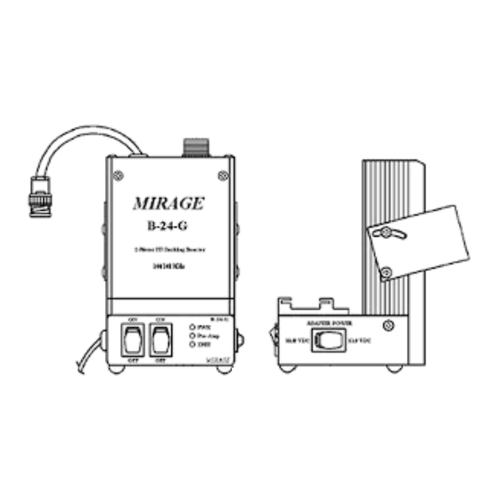
EXPLANATION OF FEATURES -- --... - Page 5 PWR INDICATOR The PWR Indicator LED indicates the amplifier is transmitting or on air. PRE-AMP INDICATOR When the PRE-AMP Indicator LED is on, it indicates the amplifier is in the RX mode and boosts the signal received. TX INDICATOR The TX Indicator LED indicates the amplifier is ON and in Stand-By mode.
- Page 6 There are various adaptors suitable for different models of handy-transceivers. MOUNTING BRACKET The mounting bracket allows easy attachment of your B-24-G to your car. ADAPTER POWER SWITCH The adaptor power can be turned OFF (middle position) when the amplifier is not in use. You can select the adaptor to be 10.8V (left position) for new HT models or...
-
Page 7: Installation
INSTALLATION -- --... -
Page 8: Diagram Of Rx Gain
DIAGRAM OF RX GAIN -- --... -
Page 9: B-24-G Optional Adaptors
B-24-G OPTIONAL ADAPTORS HAM RADIO ADAPTOR COMPATIBLE TRANSCEIVER MODEL MAKER MODEL ICOM MI-1 IC-2N, 02N, 3N, 03N, 12N, 2G, 3G, 12G, 23, etc. ICOM MI-2 IC-2S, 2SAT, 2SR, 3S, 3SAT, 3SR, 24, W2, X2, etc. ICOM MI-3 IC-W21, X21, W21T, X21T etc. - Page 10 ADAPTORS and ADAPTOR POWER SETTING HAM RADIO ADAPTOR ADAPTOR POWER MAKER MODEL SETTING ICOM MI-1 13.8 ICOM MI-2 13.8 ICOM MI-3 13.8 ICOM MI-4 10.8 YAESU MY-1 10.8 YAESU MY-2 13.8 YAESU MY-3 10.8 YAESU MY-4 10.8 KENWOOD MK-1 10.8 KENWOOD MK-2 10.8...
-
Page 11: Precautions
PRECAUTIONS To avoid malfunctions and damages, and to achieve full performance, please pay careful attention to the following matters: During transmission, the heat sink may reach a high temperature (approx. 50°C-80°C). Set the amplifier in a well- ventilated place. Do not place objects on top of the amplifier. - Page 12 Never connect the whip antenna of a handy-transceiver directly to the antenna connector of the amplifier unit using M-BNC converting connector etc. It may cause damage to the antenna due to insufficient power capacity. It may also damage the transceiver or the amplifier when strong RF signal intrusions occur.
-
Page 13: Connection Diagram
CONNECTION DIAGRAM -- --... -
Page 14: B-24-G Booster Amp. Block Circuit
B-24-G BOOSTER AMP. BLOCK CIRCUIT -- --... -
Page 15: Warranty
ONE YEAR LIMITED WARRANTY Any Mirage Communications product found to be defective in materials or workmanship will be repaired or replaced (at Mirage’s option) for a period of one year from the date of original purchase. During the warranty period Mirage Communications will provide, free of charge, both parts and labor necessary to correct defects in material or workmanship.
Need help?
Do you have a question about the B-24-G and is the answer not in the manual?
Questions and answers