
Related Manuals for Miller Dimension NT 450


Summary of Contents for Miller Dimension NT 450
- Page 1 OM-2252 218 084AA 2013−04 Processes Multiprocess Welding Description Arc Welding Power Source Dimension NT 450 Dimension NT 500 File: Multiprocess Welding Visit our website at www.MillerWelds.com...
- Page 2 We know you don’t have time to do it any other way. That’s why when Niels Miller first started building arc welders in 1929, he made sure his products offered long-lasting value and superior quality.
-
Page 3: Table Of Contents
TABLE OF CONTENTS SECTION 1 − SAFETY PRECAUTIONS - READ BEFORE USING ....... . . 1-1. -
Page 5: Section 1 − Safety Precautions - Read Before Using
SECTION 1 − SAFETY PRECAUTIONS - READ BEFORE USING som 2011−10 Protect yourself and others from injury — read, follow, and save these important safety precautions and operating instructions. 1-1. Symbol Usage DANGER! − Indicates a hazardous situation which, if Indicates special instructions. - Page 6 D Remove stick electrode from holder or cut off welding wire at FUMES AND GASES can be hazardous. contact tip when not in use. D Wear oil-free protective garments such as leather gloves, heavy Welding produces fumes and gases. Breathing shirt, cuffless trousers, high shoes, and a cap.
-
Page 7: Additional Symbols For Installation, Operation, And Maintenance
1-3. Additional Symbols For Installation, Operation, And Maintenance FIRE OR EXPLOSION hazard. BATTERY EXPLOSION can injure. D Do not install or place unit on, over, or near D Do not use welder to charge batteries or jump combustible surfaces. start vehicles unless it has a battery charging D Do not install unit near flammables. -
Page 8: California Proposition 65 Warnings
1-4. California Proposition 65 Warnings Welding or cutting equipment produces fumes or gases This product contains chemicals, including lead, known to which contain chemicals known to the State of California to the state of California to cause cancer, birth defects, or other cause birth defects and, in some cases, cancer. -
Page 9: Section 2 − Consignes De Sécurité − Lire Avant Utilisation
SECTION 2 − CONSIGNES DE SÉCURITÉ − LIRE AVANT UTILISATION fre_som_2011−10 Pour écarter les risques de blessure pour vous−même et pour autrui — lire, appliquer et ranger en lieu sûr ces consignes relatives aux précautions de sécurité et au mode opératoire. 2-1. - Page 10 Il reste une TENSION DC NON NÉGLIGEABLE dans LE SOUDAGE peut provoquer un les sources de soudage onduleur UNE FOIS incendie ou une explosion. l’alimentation coupée. Le soudage effectué sur des conteneurs fermés tels D Arrêter les convertisseurs, débrancher le courant électrique et que des réservoirs, tambours ou des conduites peut décharger les condensateurs d’alimentation selon les instructions provoquer leur éclatement.
-
Page 11: Dangers Supplémentaires En Relation Avec L'installation, Le Fonctionnement Et La Maintenance
ACCUMULATIONS LES BOUTEILLES peuvent exploser risquent de provoquer des blessures si elles sont endommagées. ou même la mort. Les bouteilles de gaz comprimé contiennent du gaz D Fermer l’alimentation du gaz comprimé en cas sous haute pression. Si une bouteille est endommagée, elle peut exploser. -
Page 12: Proposition Californienne 65 Avertissements
Les PIÈCES MOBILES peuvent RAYONNEMENT HAUTE causer des blessures. FRÉQUENCE (H.F.) risque provoquer des interférences. D Ne pas s’approcher des organes mobiles. D Ne pas s’approcher des points de coincement D Le rayonnement haute fréquence (H.F.) peut tels que des rouleaux de commande. provoquer des interférences avec les équi- pements de radio−navigation et de com- LES FILS DE SOUDAGE peuvent... -
Page 13: Principales Normes De Sécurité
2-5. Principales normes de sécurité Safety in Welding, Cutting, and Allied Processes, ANSI Standard Z49.1, Spectrum Way, Suite 100, Ontario, Canada L4W 5NS (phone: is available as a free download from the American Welding Society at 800-463-6727, website: www.csa-international.org). http://www.aws.org or purchased from Global Engineering Documents Safe Practice For Occupational And Educational Eye And Face Protec- (phone: 1-877-413-5184, website: www.global.ihs.com). - Page 14 OM-2252 Page 10...
-
Page 15: Section 3 − Definitions
A complete Parts List is available at www.MillerWelds.com SECTION 3 − DEFINITIONS 3-1. Additional Safety Symbols And Definitions Some symbols are found only on CE products. Warning! Watch Out! There are possible hazards as shown by the symbols. Safe1 2012−05 Disconnect input plug or power before working on machine. -
Page 16: Section 4 − Specifications
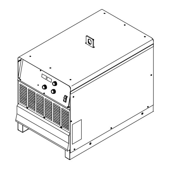
A complete Parts List is available at www.MillerWelds.com SECTION 4 − SPECIFICATIONS 4-1. Serial Number And Rating Label Location The serial number and rating information for the power source is located on the front of the machine under the weld output studs cover. Use the rating labels to determine input power requirements and/or rated output. -
Page 17: Duty Cycle And Overheating
A complete Parts List is available at www.MillerWelds.com 4-4. Duty Cycle And Overheating Duty Cycle is percentage of 10 min- utes that unit can weld at rated load without overheating. If unit overheats, thermostat(s) opens, output stops, and cooling fan runs. Wait fifteen minutes for unit to cool. -
Page 18: Volt-Ampere Curves
A complete Parts List is available at www.MillerWelds.com 4-5. Volt-Ampere Curves Volt-ampere curves show mini- mum and maximum voltage and amperage output capabilities of unit. Curves of other settings fall be- tween curves shown. A. CC Mode DC Current B. CV Mode DC Current va_curve1 −... -
Page 19: Section 5 − Installation
A complete Parts List is available at www.MillerWelds.com SECTION 5 − INSTALLATION 5-1. Selecting A Location Special installation may be required where gasoline or volatile liquids are present − see NEC Article 511 or CEC Section 20. Lifting Eye Movement Lifting Forks Use lifting eye or lifting forks to move unit. -
Page 20: Tipping
A complete Parts List is available at www.MillerWelds.com 5-2. Tipping Do not move or operate unit where it could tip. 5-3. 115 VAC Receptacle And Supplementary Protectors Turn power before connecting to receptacle. 115 V 15 A AC Receptacle RC15 Power is shared between RC15 and Remote 14 receptacle RC14 (see Section 5-7). -
Page 21: Weld Output Terminals And Selecting Cable Sizes
**Weld cable size (AWG) is based on either a 4 volts or less drop or a current density of at least 300 circular mils per ampere. ( ) = mm for metric use ***For distances longer than those shown in this guide, call a factory applications rep. at 920-735-4505 (Miller) or 1-800-332-3281 (Hobart). Ref. S-0007-J 2011−07 OM-2252 Page 17... -
Page 22: Connecting Weld Output Cables
A complete Parts List is available at www.MillerWelds.com 5-5. Connecting Weld Output Cables Tools Needed: 3/4 in. (19 mm) 803 778-B cable terminal and copper bar. Make Weld Cable Terminal Turn off power before connecting to sure that the surfaces of the weld cable weld output terminals. -
Page 23: Connecting Remote Control
A complete Parts List is available at www.MillerWelds.com 5-7. Connecting Remote Control Turn off power before con- necting to Remote 14 recep- tacle. Remote 14 Receptacle RC14 Connect remote control to RC14. C L N Ref. 800 166-D / Ref. S-0004-A / S-0750 5-8. -
Page 24: Placing Jumper Links
A complete Parts List is available at www.MillerWelds.com 5-9. Placing Jumper Links Disconnect and lockout/tag- out input power before installing or moving jumper links. Check input voltage available at site. Jumper Link Label Check label. Jumper Links Tools Needed: Move jumper links to match input 3/8 in. - Page 25 A complete Parts List is available at www.MillerWelds.com Notes OM-2252 Page 21...
-
Page 26: Connecting 3-Phase Input Power
A complete Parts List is available at www.MillerWelds.com 5-10. Connecting 3-Phase Input Power = GND/PE Earth Ground IMPORTANT Input Contactor L1 (U) L2 (V) L3 (W) GND/ PE Earth Ground Tools Needed: 3/8 in. 3/8 in. input3 2013−04 − 800 103-C / Ref. 801 116-A OM-2252 Page 22... - Page 27 A complete Parts List is available at www.MillerWelds.com 5-10. Connecting 3-Phase Input Power (Continued) applicable, use lugs of proper amperage Connect input conductors L1, L2 and L3 to Installation must meet all National capacity and correct hole size. welding power source line terminals. and Local Codes −...
-
Page 28: Section 6 − Operation
A complete Parts List is available at www.MillerWelds.com SECTION 6 − OPERATION 6-1. Controls 229 448-F Power Switch is maximum output available through the re- voltage. This allows the operator to use a mote control. In the MIG, CC, and V-Sense very short arc length without sticking the This unit is equipped with a fan motor that feeder modes, a remote control provides full... -
Page 29: Meter Functions For Cc/Cv Models
A complete Parts List is available at www.MillerWelds.com 6-2. Meter Functions For CC/CV Models The meters display the actual weld output values for approximately three seconds after the arc is broken. Mode Meter Reading At Idle 78.0 Scratch Start TIG Actual Volts (OCV) Preset Amps Lift-Arc TIG... -
Page 30: Section 7 − Maintenance & Troubleshooting
A complete Parts List is available at www.MillerWelds.com SECTION 7 − MAINTENANCE & TROUBLESHOOTING 7-1. Routine Maintenance Disconnect power before maintaining. Maintain more often during severe conditions. Δ = Repair n = Check Z = Change ~ = Clean l = Replace * To be done by Factory Authorized Service Agent Every Months... -
Page 31: Voltmeter/Ammeter Help Displays
A complete Parts List is available at www.MillerWelds.com 7-3. Voltmeter/Ammeter Help Displays All directions are in reference to the front of the unit. All circuitry referred to is located inside the unit. Help 0 Display Indicates a shorted thermistor in the transformer of the unit. -
Page 32: Troubleshooting
A complete Parts List is available at www.MillerWelds.com 7-4. Troubleshooting Trouble Remedy No weld output; unit completely inop- Place line disconnect device in On position (see Section 5-10). erative; pilot light PL1 off. Check for open line fuse(s), and replace if open (see Section 5-10). Check for proper input power connections (see Section 5-10). -
Page 33: Section 8 − Parts List
A complete Parts List is available at www.MillerWelds.com SECTION 8 − PARTS LIST 8-1. Recommended Spare Parts Dia. Part Mkgs. Description Quantity Recommended Spare Parts ..156065 ..Fuse Crtg, .5 amp 600 V time delay . -
Page 34: Section 9 − Electrical Diagram
A complete Parts List is available at www.MillerWelds.com SECTION 9 − ELECTRICAL DIAGRAM Figure 9-1. Circuit Diagram For Dimension NT OM-2252 Page 30... - Page 35 A complete Parts List is available at www.MillerWelds.com 263 029-A OM-2252 Page 31...
- Page 36 Notes TM-216 869 Page 32 Dynasty 350/700, Maxstar 350/700...
- Page 37 Notes...
- Page 38 Notes...
- Page 39 Effective January 1, 2013 (Equipment with a serial number preface of MD or newer) This limited warranty supersedes all previous Miller warranties and is exclusive with no other guarantees or warranties expressed or implied. Warranty Questions? LIMITED WARRANTY − Subject to the terms and conditions below, 6 Months —...
-
Page 40: Options And Accessories
Contact the Delivering Carrier to: File a claim for loss or damage during shipment. For assistance in filing or settling claims, contact your distributor and/or equipment manufacturer’s Transportation Department. © ORIGINAL INSTRUCTIONS − PRINTED IN USA 2013 Miller Electric Mfg. Co. 2013−01...
Need help?
Do you have a question about the Dimension NT 450 and is the answer not in the manual?
Questions and answers