Kenwood KDC-MP638U Service Manual
Hide thumbs
Also See for KDC-MP638U:
- Training manual (52 pages) ,
- Instruction manual (116 pages) ,
- Instruction manual (75 pages)
Advertisement
Quick Links
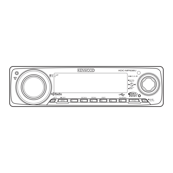
CD RECEIVER
KDC-MP638U/W7041U
/W7141UY/X692/X7009U
SERVICE MANUAL
TDF SPARE-PANEL
MODEL
TDF PANEL No. TDF NAME
KDC-X692
Y33-2940-62
KDC-MP638U
Y33-2940-63
KDC-W7041U/W7141UY
Y33-2940-65
KDC-X7009U
Y33-2940-67
KDC-MP638U
(K type)
KDC-W7041U
KDC-W7141UY
(E type)
KDC-X692
(K type)
KDC-X7009U
(M type)
DC cord (K,M type)
Plastic cabinet assy (M type)
(E30-6428-05)
(A02-2757-03)
DC cord (E type)
Carrying case
(E30-6671-05)
(W01-1664-05): KDC-X692
(W01-1710-05): K,E type
Screw set (KDC-X692)
(N99-1790-05)
TDF-87DX
TDF-MP87D
TDF-W7041U
TDF-X7009U
Remote controller assy
(A70-2085-05):
Compact disc
(W01-1723-05)
Cover (KDC-X692)
Screw set (K,M type)
(F19-1475-04)
(N99-1757-15)
© 2008-3 PRINTED IN JA PAN
B53-0627-00 ( N ) 429
CD MECHANISM EXTENSIONCORD (30P) : E39-1014-05
KDC-MP638U
KDC-W7141U
KDC-X692
KDC-X7009U
except KDC-W7041U
SIZE AA BATTERY
(Not supplied)
RC-547
Lever
(D10-7012-04) x2
Screw set (K,M type)
(N99-1730-35)
This product uses Lead Free solder.
This product complies with the
Panel assy
(A64-4427-02)
Panel assy
(A64-4429-02): KDC-W7041U
(A64-4430-02): KDC-W7141UY
Panel assy
(A64-4426-02)
Panel assy
(A64-4432-02)
Escutcheon
(B07-3235-03): KDC-X692
(B07-3238-03): K,E,M type
Mounting hardware assy
(J22-0011-03)
RoHS
directive for the European market.
Advertisement


Need help?
Do you have a question about the KDC-MP638U and is the answer not in the manual?
Questions and answers