Table of Contents
Advertisement
Quick Links
Advertisement
Table of Contents

Related Manuals for Additel 762


Summary of Contents for Additel 762
- Page 1 Automated Hydraulic Pressure Calibrator...
- Page 3 Additel 762 Automated Hydraulic Pressure Calibrator -------- User Manual Please download the latest version from www.additel.com [Version:2301V01] Additel Corporation...
- Page 5 This user manual provides operating and safety instructions for the ADT762 Automated Hydraulic Pressure Calibrator. To ensure correct operation and safety, please follow the instructions in this manual. Additel Corporation reserves the right to change the contents and other information contained in this manual without notice...
-
Page 7: Table Of Contents
Content Safety instructions ................................. 1 Cautious ..................................2 1. Introduction ................................3 1.1 Overview ................................3 1.2 Features ................................3 1.3 Pressure Specifications ............................5 1.4 Other Specifications ............................7 2. Installation ................................. 11 2.1 Features ................................11 2.1.1 Basic structure ............................11 2.1.2 Electrical and signal port ......................... - Page 8 2.2.3 Open the display ............................. 18 2.3 Getting started..............................19 2.3.1 Power on ..............................19 2.3.2 Setting the system date and time ......................19 2.3.3 Generating a pressure ..........................19 2.3.4 Display and operation ..........................20 2.3.5 Powering off the unit ..........................20 3.
- Page 9 3.3.2 Switch test ............................... 35 3.3.3 HART Communication ..........................37 3.3.4 PROFIBUS PA communication ....................... 44 3.4 Electrical output..............................46 3.5 External pressure module ..........................49 3.6 Typical applications on main page ........................51 3.6.1 Pressure gauge calibration ........................51 3.6.2 Pressure transmitter Calibration ......................
- Page 10 4.3 Power management ............................65 4.3.1 Display brightness ........................... 65 4.3.2 Battery information ..........................65 4.3.3 Energy settings ............................65 4.4 System calibration ............................. 66 4.4.1 Calibration of electrical measurement ..................... 67 4.4.2 Auto tune ..............................68 4.4.3 Calibration of the pressure source module ..................... 69 4.4.4 Calibration of the pressure module ......................
- Page 11 4.6 Personalization..............................76 4.6.1 Date and time ............................76 4.6.2 Language ..............................76 4.6.3 Sound ..............................76 4.6.4 CSV file ..............................77 4.7 Cloud service ..............................77 4.8 Data management ............................. 78 4.9 Product information ............................78 4.9.1 Host information ............................79 4.9.2 Control board information........................
- Page 12 5.1.2 Pressure transmitter ..........................82 5.1.3 Pressure switch ............................83 5.1.4 Pressure sensor ............................84 5.1.5 I/P converter ............................84 5.1.6 Signal isolator ............................85 5.2 Task ................................... 85 5.2.1 Dial pressure gauge ..........................86 5.2.2 Digital pressure gauge ..........................90 5.2.3 Pressure transmitter ..........................
- Page 13 6.3 Data log ................................111 7. HART Communicator .............................. 113 7.1 HART connection and search .......................... 113 7.2 HART communicator operation ........................113 8. System maintenance............................... 115 8.1 Device information view ........................... 115 8.2 Diagnostic information ............................115 8.3 Check the sealing performance of the calibrator ....................115 8.4 Maintenance ..............................
- Page 14 Figure content Figure 1 Basic structure ............................11 Figure 2 Electrical and signal port ........................... 14 Figure 3 Battery installation ............................. 17 Figure 4 Connect to DUT ............................18 Figure 5 Filling diagram ............................20 Figure 6 Home screen ............................. 21 Figure 7 Remove the single port ..........................
- Page 15 Figure 18 Current output of internal power supply ....................47 Figure 19 Connection of the external module ......................50 Figure 20 Connect a dial pressure gauge ....................... 52 Figure 21 Connect a digital pressure gauge ......................52 Figure 22 Calibration of a 2-wire pressure transmitter .................... 54 Figure 23 Calibration of a 3-wire pressure transmitter ....................
- Page 16 Table Content Table 1 Selection guide ............................. 5 Table 2 Optional external CDP module ........................6 Table 3 Functional specifications ..........................7 Table 4 Electrical measure specification ........................8 Table 5 General specifications ..........................9 Table 6 Basic structure ............................. 11 Table 7 Electrical and signal port ..........................
- Page 17 Table 18 Setup of wireless communication ......................63 Table 19 Bluetooth setup ............................64 Table 20 Serial set up .............................. 64 Table 21 Date and time ............................76 Table 22 Sound setup ............................. 76 Table 23 Setup of cloud service ..........................78 Table 24 Task mode dial pressure gauge information .....................
-
Page 19: Safety Instructions
◆ Before using the device, please check its appearance for any damage; ◆ Do not operate the device in any orientation other than the upright; ◆ In case of the device is damaged or malfunctions, please do not use it and contact Additel; 2. Electrical:... -
Page 20: Cautious
◆ Do not apply more than 30V between any two electrical jacks (except for voltage measurement jacks); ◆ Do not use any adapter other than Additel power adapter designed for the ADT762. Charge the battery as soon as the battery symbol indicates. -
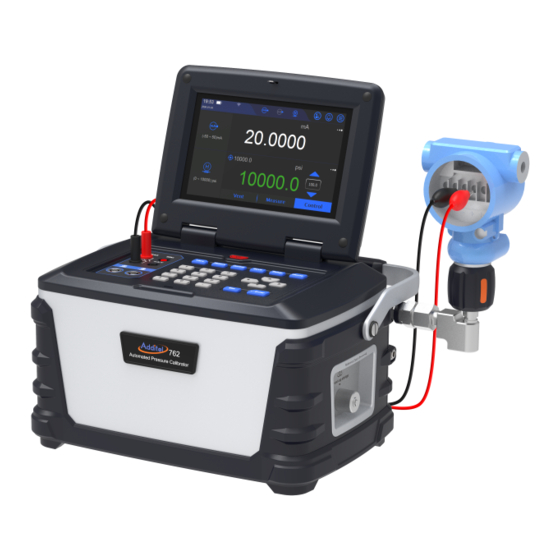
Page 21: Introduction
1. Introduction 1.1 Overview The Additel 762 Automated Pressure Calibrator is unlike any other pressure calibrator on the market. This revolutionary product is a complete turnkey solution for automation of pressure calibration work up to 10,000 PSI. Designed for use in both the field and the laboratory, the portability and accuracy of this state-of-the-art product will quickly become the favorite go-to calibrator for lab personnel and field technicians alike. - Page 22 PC or tablet. The ADT762 automatically analyzes errors, generates test reports, while storing results locally. The Additel 762 can support up to 1000 documented tasks which can be stored and recalled at any time to help save time and money.
-
Page 23: Pressure Specifications
1.3 Pressure Specifications Table 1 Pressure Specifications Model ADT762 Automated Hydraulic Pressure Calibrator Specification Pressure Range 15~10,000 psi (1-700 Bar) Range Selection Manual 3K psi, Manual 10K psi or Auto-range 0~10,000 psi, 0.01%FS 0~10,000 psi, 0.02%FS Accuracy 0~3,000 psi, 0.01%FS 0~3,000 psi, 0.02%FS Maximum External Load Capacity Max: 80 ml@700 Bar, 50 ml recommend... - Page 24 [1] Control Stability is based on the range selection or external module. Table 2 Optional external ADT161 module Specification Pressure Range Accuracy Pressure Type Media Model (psi) (bar) 1,000 0.01% FS Gauge 1,500 0.01% FS Gauge ADT161-01-GPXX 2,000 0.01% FS Gauge 0.01%FS 3,000...
-
Page 25: Other Specifications
1.4 Other Specifications 1. Functional Specification Table 3 Functional Specification Functional Specification Details ≤0.005%FS,customizable Stability External module See Table 2 Pressure type Gauge pressure Medium Diethylhexyl sebacate, water medium (762W) Maximum external load volume Max: 80 ml@700 Bar, 50 ml recommend Maximum liquid volume 350ml,Press-type through air vent, the user can quickly Liquid tank change the filter... - Page 26 2. Electrical specification (Environment temperature 20℃±5℃, 1 year accuracy) Table 4 Electrical specification Model Range Resolution Accuracy Note Specification -25 to 25 mA 0.1 μA ± (0.008%RD + 1.0 μA) Impedance <10 Ω mA Measure -50 to 50 mA 0.1 μA ±...
- Page 27 Misuse Protection Up to 30 V on any two sockets Pressure Switch Test HART / PROFIBUS PA 3. General specification Table 5 General specification Specification Description User Interface Color touch screen and keypad operation Display 7’’ TFT touch screen 800 x 480 color Enclosure IP Rating IP31 Power...
- Page 28 Storage temperature: -20 °C to 60 °C ( -4 °F to 120 °F) Humidity: <90%, non-condensing Certification ISO 17025 accredited certificate of calibration with NIST-traceable data Compliance Software Compatibility ACal, Additel Land and Additel Link for access via mobile application Warranty 1 year...
-
Page 29: Installation
2. Installation 2.1 Features 2.1.1 Basic structure Figure 1 Basic structure... - Page 30 Table 6 Basic structure Item Name Screen Electrical testing ports Pressure module ports On/Off Shortcut keys Navigation keys Numeric Keypad Output port Hanging strap Block Zeroing return manifold communication port Display assembly clamp Medium Refill / Reservoir vent port Medium viewing window Label LAN Interface...
- Page 31 USB slave port Power supply USB master port Head correction reference line Battery...
-
Page 32: Electrical And Signal Port
2.1.2 Electrical and signal port Figure 2 Electrical and signal port Table 7 Electrical and signal port Port Description ①② Current, Voltage, Switch measurement and HART, Profibus PA bus communication, Red is positive , Black is negative ④⑤ Current, Voltage and power output, Red is positive , Black is negative... -
Page 33: Keypad
③ Jack A for connecting external pressure module ⑥ Jack B for connecting external pressure module DC27V Power adapter connection port Ethernet port USB-A USB master, for flash drive connection USB-B USB slave, for computer connection 2.1.3 Keypad Table 8 Keypad function Item Keypad Description... -
Page 34: Liquid Port
Shortcut Key: Setup interface Shortcut Key: Return home Shortcut Key: Cancellation or Return function Shortcut Key: Fulfillment or confirmation function Navigate key: Up, down, left, right key Numeric Key 2.1.4 Liquid port OUTLET: The pressure output interface is connected to the equipment to be calibrated. The volume of the calibration equipment should not be too large. -
Page 35: Connect To Dut
so that the battery lock is in a locked state, as shown in ② in the figure; remove the battery: reverse the operation and push the battery manually lock, make the battery lock unlocked, and remove the battery, as shown in Figure ③, be careful that the battery falls during this process. -
Page 36: Open The Display
Figure 4 Connect to DUT 2.2.3 Open the display Push the lock on the cover to the right to open the screen to a suitable angle. -
Page 37: Getting Started
2.3 Getting started 2.3.1 Power on ◆ Press to turn the power on. ◆ The startup screen shows the manufacturer's logo. ◆ After a short time the system enables the home screen. ◆ Connect the power supply for charging if power is low. ◆... -
Page 38: Display And Operation
Figure 5 Filling diagram 2. Reinstall the cover and press the button to make it in state III In use ) ; 3. If the output port is not connected to a pressure UUT device, the output port needs to be effectively blocked. 4. -
Page 39: Display And Operation
2. When the power adaptor is connected, please disconnect the adaptor at first. If the battery is installed, refer to above step. 3. Display and Operation 3.1 Home screen The home screen contains top status bar and modules functional areas, see figure 6. Figure 6 Home screen... -
Page 40: Status Bar
3.1.1 Status bar The status bar contains 3 parts: Status information, Module display/hidden operation and Function navigation. 1. Status information display area ◆ Date and time ◆ Wi-Fi: Icon indicates Wi-Fi connection status and signal intensity. ◆ LAN: Icon indicates network activity. ◆... - Page 41 ◆ Electrical output module display/hidden: Different icons will be displayed according to different electrical output features. When the icon shows, it indicates the mA output is working. Click icon, the output features part will be hidden, but the arrow on the icon will be flickering to indicate it’s still working. ◆...
-
Page 42: Module Function Display Area
3.1.2 Module function display area The module function display area is divided into electrical measurement area, electrical output area, external pressure module A and B (only when pressure modules are connected). Clicking "Module function display/hide operation area" in the status bar to show and hide the above functions, at the same time, module function display can be set from one to five screens. -
Page 43: Pressure Control
3.2 Pressure control 3.2.1 Pressure output 1. Connection (1) Output the pressure using internal module , please refer to the Figure 4 to connect the UUTs. (2) If wants to use external modules , need a ADT107 manifold (Optional), and please follow the below steps to make the connection. - Page 44 Take out the whole assembly (arrow ②). 2) Make connections with the ADT107 manifold and external modules, as shown in figure 8. Figure 8 External pressure control connection (with ADT107 manifold)
- Page 45 Table 9 External pressure control connection Description ① Cable for external pressure module ② External pressure module ③ ADT107 Dual ports manifold with zero returning (Optional) ④ Zero return communication cable ⑤ ADT100-762Hose 2. Select the range (1) In the status bar, press ;...
- Page 46 ◆ Press to go to Step mode. ◆ The set value must meet the pressure control range of the calibrator. For the pressure control range, please refer to Para. 1. 6 Technical Specifications; ◆ When target pressure exceeds current pressure range of the internal module but within the range of the second internal module, it will switch to the applicable module.
- Page 47 Step mode Step point, percent, unit, default Incrementing mode of auto step Cycle interval 0-3600 seconds Stop time between every cycle end and the next cycle start Dwell time 0-3600 seconds The time is pressure stable at each step Step quantity 2-17 The number of steps Range will be based on the largest...
-
Page 48: Pressure Measurement
3.2.2 Pressure measurement 1. Switch to pressure measurement status: High- or Low-pressure range 2. Connection: Refer to the Figure 4. 3. External pressurization ◆ Do not pressurize the calibrator beyond the measuring module range. ◆ When external pressure exceeds the current range, the value turns red and alarms at the same time. ◆... -
Page 49: Current/Voltage Measurement
3.3.1 Current/Voltage measurement 1. Click the input icons like on the status bar to display the electrical measurement. Click the ranges area on the screen to switch the current and voltages measurements. Do not apply current/voltage outside the calibrator’s range. ... - Page 50 Figure 9 Current measurement...
- Page 51 Figure 10 Voltage measurement 3. Functional operation (1) Zeroing: Zero the measurement to eliminate the zero drift. The allowable zeroing range is 0.1%FS. For automatic mode, it will use the smallest range to calculate. (-30~30)V: calculate by (-5~5)V (-300~300)mV: calculate by(-300~300)mV...
- Page 52 (-50~50)mA: calculate by(-25~25)mA (2) Scaling: Converts the current/voltage signals into pressure signal. Table 11 Scaling parameters Subject Valid value Description Transfer function Type of the conversion function of the scaled Linear, square root, square value Percentage of the input range of scaling Input range 0%~100% Depend on the electrical measurement selected...
-
Page 53: Switch Test
Applicable to the first-order filter. Coefficient 0.01~1 Sampling number of the average filter, correlated with the Filter sampling number Integer 1~100 sampling time. Sampling time of the average filter, correlated with the Filter sampling time 0~20 s sampling number. Extremum pair number of the average filter to be Extremum pair number Integer 0~10 removed. - Page 54 Figure 11 Mechanical Switch Figure 12 NPN Switch Figure 13 PNP Switch 3. Action value The switch action values are recorded only when the output item is pressure. Only a pair of action values is recorded, including the switch state (on to off/off to on) when triggered and pressure value.
-
Page 55: Hart Communication
Press and select "Reset", to clear the action values. Press and select "Switch Setup", to switch between mechanical switch, NPN switch and PNP switch. 3.3.3 HART Communication The calibrator supports HART bus communication, uses simplified files, and provides setting maintenance and calibration for general and common parameters of HART pressure transmitters. - Page 56 2) For the connection mode with external power supply and external resistance, see Figure 15. 3) For the connection mode with internal power supply and external resistance, see Figure 16. 4) For the connection mode with external power supply and internal resistance, see Figure 17. Figure 14 HART internal power / resistance Figure 15 HART external power / resistance Figure 16 HART internal power / external resistance...
- Page 57 During the search process, press the key or at top right to stop searching and return to the power configuration interface. During the search process, click at top right to abort the search. After searched, you can press the key to conduct a new search.
- Page 58 key for confirmation, so as to switch primary and secondary display. During task calibration of a HART transmitter, you shall first select the HART process variables to be calibrated. 4. Setup (1) Parameters Under the main interface, switch to HART electrical measurement. Press to view and set HART parameters.
- Page 59 Common version Read-only parameter Software version Read-only parameter Hardware version Read-only parameter Device version Read-only parameter Sensor S/N Read-only parameter Sensor unit Read-only parameter Sensor Lower sensor limit Read-only parameter Upper sensor limit Read-only parameter Minimum sensor range Read-only parameter It can be modified to any unit supported by the transmitter.
- Page 60 Alarm status Read-only parameter 2) Operation Under the HART setup interface, press the key to view HART parameter values in real time; select a parameter that can be set, then press the key or click the screen to enter the set state. ...
- Page 61 zeroing interface. Ensure that the present measured value adequately approaches zero; otherwise, it may cause zeroing to fail. (3) Current regulation Adjust the proportion of current output of the transmitter, to make its AO value consistent with the actually output loop current.
-
Page 62: Profibus Pa Communication
limits as trim values (the lower range limit corresponds to the lower-point trim value, and the upper range limit corresponds to the high-point trim value). In this case, you can input any value. Execute the adjustment (Trim) command. After completed successfully, the PV value will change with the executed trim point value. - Page 63 1. Device description (DD) file The DD file is used to describe device parameters and parameter access modes. Through the parameter description information, you can view and set related parameters of the PA transmitter. The calibrator uses specific device description files, to access main parameters in the Physical Block, Transducer Block and Function Block of PA transmitter.
-
Page 64: Electrical Output
Before modification of some parameters, you may need to modify corresponding TARGET_MODE (e.g. set it to OOS, Auto, Man, and so forth). Specifically, you can follow the user manual of PA transmitter to modify related parameters. (2) Calibration Click , then a function menu will pop up. - Page 65 Figure 18 Current output of internal power supply 3. Enabling loop power (for current supply only) According to the connection mode, press the key and select whether to enable loop power. Power will be supplied as soon as loop power is enabled. 4.
- Page 66 The set value shall meet the calibrator's current output range of 0~25mA, voltage output range of 0~16V, and power supply output range of 16~30V. 5. Auto step Press the key to enter the auto step setup. For the auto step parameters, see Table 14. Table 14 auto step parameters Subject Valid value...
-
Page 67: External Pressure Module
6. Manual step Press the key on the keyboard or on the screen, to manually step through values. You can click the number inside to set the step value of manual step. 7. Ramp Press the key to enter the Ramp setup interface (only 0~25mA and 0~16V is applicable). For the Ramp output parameters, see Table 15. - Page 68 Figure 19 Connection of the external module 2. Display of the external pressure module When the pressure module is connected properly, the status bar will display the online icon of pressure module. The calibrator supports two external pressure modules A and B, and provides multi-screen display with other features.
-
Page 69: Typical Applications On Main Page
When the external pressure modules A and B are both connected, the calibrator can show up to five channels in the multi-screen. If the measured value exceeds the present range of pressure module, it will turn red and give an alarm. ... - Page 70 Connect the gauge as shown in Figure 20 (dial pressure gauge)/21 (digital pressure gauge). Figure 20 Connect a dial pressure gauge Figure 21 Connect a digital pressure gauge Manually set or use the step function (see Para. 3.2.1 "Auto step and manual step of pressure output") to output the pressure of each calibration point.
-
Page 71: Pressure Transmitter Calibration
3.6.2 Pressure transmitter Calibration The calibrator supports calibration of 2-wire, 3-wire and 4-wire pressure transmitters. 1. Prepare Select the pressure output in menu. Open the pressure output area of main operation interface: High-pressure or low-pressure range (depends on the range of the transmitter). - Page 72 Figure 22 Calibration of a 2-wire pressure transmitter Figure 23 Calibration of a 3-wire pressure transmitter...
-
Page 73: Hart Transmitter Calibration
Figure 24 Calibration of a 4-wire pressure transmitter 3. Manually set or use the step function (see Para. 3.2.1 "Auto step and manual step of pressure output") to output the pressure of each calibration point. 4. When the pressure of each calibration point becomes stable and is displayed in green, record the output value of the transmitter at each point, or use the snapshot feature. -
Page 74: Pressure Switch Calibration
the range of the transmitter). Switch the electrical measurement item of main operation interface to: Current measurement. 2. Connection Connect the hydraulic circuit as shown in Figure 4; connect the electrical circuit as shown in Figure 14-17. 3. Make connection (see Para. 3.3.1). During setup, switch the process variable to current output. 4. -
Page 75: I/P Converter
Figure 25 Calibration of a pressure switch 3. Capture of the action value To capture more accurate action values, you can enter "control settings” and set the slew rate to a lower value which will reduce the lag time. ... - Page 76 Switch the electrical output item of main operation interface to: Current output. Open the pressure output area of main interface and switch to the measurement state: High-pressure or low-pressure range (depends on the range of the I/P converter). ...
-
Page 77: Setup
If the loop power supply of calibrator is used (the maximum load is 50 mA), please check the load capacity. 3. The I/P converter shall use the manual or automatic step function of electrical output (see Para. 3.4 Electrical output), to successively output current of each calibration point. - Page 78 Input the pressure stability: One of pressure stability conditions. Compare the difference between the output pressure and set pressure with this value. Its range is ± (0.005~1)%FS. 4. Stabilization time Input the pressure stabilization time: One of pressure stability conditions. Pressure control is considered stable when the difference between the output pressure and set pressure meets requirements and lasts for this duration.
-
Page 79: Communication
The density can be selected from: distilled water, Sebacate oil or user-defined value; The Head correction can be input within the range of (-1000~1000) cm. The acceleration can be input within the range of (9~10) m/s Zero return: disabled/ enabled. -
Page 80: Wireless Communication
Table 16 Network connection Subject Valid value Description DHCP/Static Select the acquisition mode of device address. Address acquisition When the DHCP mode is selected, the content of the table below will be allocated by the system automatically and are read-only items. ... - Page 81 Table 18 Wireless network selection Subject Valid value Description WLAN Open or Close the WLAN Open/Close Select the device address acquisition method Advancec options DHCP/Static Wireless network access point selection SSID Depends on network environment The port number and physical address are factory settings and cannot be modified. ...
-
Page 82: Bluetooth
4.2.3 Bluetooth The calibrator is connected through Bluetooth to mobile APPs for communication. Table 20 Bluetooth setup Subject Valid value Description Enable or disable the Bluetooth function. Bluetooth state Enable/disable Support Chinese characters, letters, numbers or Set the Bluetooth name of calibrator. Bluetooth name symbols. -
Page 83: Power Management
Data bit 5, 6, 7, 8 Data bit set Stop bit None, One, Two, One Point Five Stop bit set 4.3 Power management 4.3.1 Display brightness The LCD brightness of calibrator can be modified by adjusting the brightness progress bar. 4.3.2 Battery information Display the present connection state and information of the battery. -
Page 84: System Calibration
During pressure control, auto step or task execution, this function does not take effect. 2. Auto sleep In case there is no key and serial port command operations within a set time, it will automatically sleep. There are 4 types of auto-sleep setting: never, 1 min, 5 min and 30 min. ... -
Page 85: Calibration Of Electrical Measurement
calibrator. Provided is a factory reset function to restore calibration data to factory settings. When performed the calibration date is restored to "----/--/--". You need to use a standard device with higher accuracy for calibration. On the setup interface, enter system calibration and select an item to be calibrated. ... -
Page 86: Auto Tune
the right side of screen or press the key to record and continue. Before final completion of calibration, you can return to the previous operation by using the icon or key anytime, until exiting the entire calibration function. This calibration will not take effect. ... -
Page 87: Calibration Of The Pressure Source Module
Figure 27 Auto tune connection 4.4.3 Calibration of the pressure source module The internal pressure control module is used to calibrate the pump source pressure sensor, booster front pressure sensor, etc. inside the calibrator to correct the pressure drift caused by the long-term operation of the internal sensor, and the pressure outlet needs to be closed during execution. - Page 88 reference pressure instrument; When selecting the external pressure mode, please connect the calibrator to the standard pressure output liquid circuit; When calibrating an external pressure module, if the pressure range of the internal pressure source covers the pressure module to be calibrated, internal or external pressure can be selected. When not covered, only external pressurization can be selected.
-
Page 89: Calibration Expiration Reminder
pressure is stabilized, click to do the next point calibration. Note: Please adjust the reference gauge pressure output to be the same as the set value of the calibrator. If the measured value deviates too much from the calibration point, there will be a prompt After the calibration is successful, the new calibration data will take effect immediately, and the calibration date will become the current system date 4. -
Page 90: Maintenance
1) Copy the upgrade file under the root directory of USB flash drive (ensure that the format of USB flash drive is FAT16 or FAT32). 2) After power-on, insert the USB flash drive into the USB-A port on the left side of calibrator. 3) Select "Upgrade via USB"... -
Page 91: Factory Reset
Data export: DB file export of tasks, etc. Advanced settings: Filter settings of the control module, setting and enabling of the power-on password, liquid level power-on reminder switch, zero return settings etc. Process diagnosis: Including self-diagnosis of some functional modules in the equipment, which is used for fast locate the problem in case of malfunction. -
Page 92: Liquid Exhaust
shutdown. 2. Operating procedures After entering the application, click button to enter the maintenance and draining process, you can click the button to stop in the middle. Waiting for the progress to complete, a pop-up window prompts. 4.5.5 Liquid Exhaust 1. -
Page 93: Piston Maintenance
pump running. 2. Operation In case of the pressure is too high, vent it at first. Click and wait the vent finishes, then refer to Figure 28. Follow the steps in Figure 28 to prepare for the liquid replacement. ... - Page 94 Click button to start piston maintenance. Click button to stop piston maintenance. 4.6 Personalization Personalization includes date and time, language, and sound settings. 4.6.1 Date and time Table 22 Date and time Subject Valid value Description Time 00:00~23:59 Set the time.
- Page 95 4.7 Cloud service 1. Provided through Ethernet or Wi-Fi methods for connection to the ACIoud service. Through Additel Link (providing several client modes such as mobile APP and PC), users can monitor the real-time operation status and data of the device anytime anywhere.
- Page 96 Table 24 Setup of cloud service Subject Valid value Description Enable or disable the cloud service function. Enable On/off 4.8 Data management Perform management by function modules. Data management of each function is under the corresponding item, it’s for user convenience. ...
- Page 97 4.9.1 Host information Includes the model, serial number, host version, system firmware version, system hardware version, power-on times, operation time, etc. Generally, the firmware version refers to host version. When contacting customer service, please provide this information. 4.9.2 Control board information ...
- Page 98 4.9.5 Wireless module information Include the Wi-Fi version, Bluetooth version, etc. 4.9.6 PROFIBUS module information Include the firmware version and hardware version of PROFIBUS module. The PROFIBUS module is used to realize related functions of communication with transmitters. 4.9.7 HART communicator information Includes the DD library version, etc.
- Page 99 Connect as shown in Figure 20 when testing a dial pressure gauge; Connect as shown in Figure 21 when testing a digital pressure gauge. 2. Start the test Click the zeroing button to reset the pressure control module. ...
- Page 100 5.1.2 Pressure transmitter Select the “pressure transmitter” icon in the test type list to start the quick test for pressure transmitter. 1. Connection Refer to Para. 3.6.2 for connection. 2. Start the test Click the zeroing button to reset the pressure control module. ...
- Page 101 5.1.3 Pressure switch Select the “pressure switch” icon in the test type list to start the quick test. 1. Connection Connect the switch as shown in Figure 25. 2. Start the test Click the zeroing button to reset the pressure control module; ...
- Page 102 To redo the test click the reset button 5.1.4 Pressure sensor Select the “pressure sensor” icon in the test type list to start the quick test. 1. Connection Connect the sensor as shown in Figure 29. 2. Start the test Same as Para.
- Page 103 5.1.6 Signal isolator Select the “signal isolator” icon in the test type list to start the quick test. 1. Connection Connect as shown in Figure 30. 2. Start the test Same as Para. 5.1.2 Pressure transmitter. 3. Save the result Same as Para.
- Page 104 5.2.1 Dial pressure gauge 1. Connection Connect the calibrator and the dial pressure gauge as shown in Figure 20. 2. New task Select the “Dial pressure gauge” icon in the test type list and input the information of the pressure gauge. Table 25 Task mode dial pressure gauge information Subject Valid value...
- Page 105 Location Letter, numeral, symbol Location position of the pressure gauge Letter, numeral, symbol Notes of the pressure gauge Note 3. Task setting features Select the task in the task list to enter the instrument parameter interface, click the start icon to enter the execution information interface, and input the calibration information of the pressure gauge.
- Page 106 4. Task start Click to start the task process: (1) If connecting an external pressure module, it needs to select an input reference. (2) Click on the right to zero the pressure module. (3) Click the task start button at the bottom right and select the execution mode as automatic execution or manual execution.
- Page 107 5. Task end The ADT762 provides calibration task data review, sorting and save functions. After the task is over, the user can choose to see the result of the task through the data view icon or the task data. ...
- Page 108 5.2.2 Digital pressure gauge 1. Connection Connect the calibrator and digital pressure gauge as shown in Figure 21; 2. New task Select the “digital pressure gauge” icon in the test type list. The other contents are the same as those in Para. 5.2.1 New Task for Calibration of the dial pressure gauge.
- Page 109 Select the “pressure transmitter” icon in the test type list, and input the information of the calibrated pressure transmitter in turn: Table 28 Task mode pressure transmitter information Subject Valid value Description Letter, numeral, symbol Name of the pressure transmitter Name Letter, numeral, symbol Serial number of the pressure transmitter...
- Page 110 Owner Letter, numeral, symbol Owner of the pressure transmitter Location Letter, numeral, symbol Location of the pressure transmitter Letter, numeral, symbol Notes of the pressure transmitter Notes 3. Task setting For the contents, refer to Para. 5.2.1 Task settings for calibration of the dial pressure gauge. 4.
- Page 111 in Figure 29. 2. New task Select the “pressure transducer” icon in the test type list and input the information of the pressure transducer. Figure 29 Calibration of the pressure transducer...
- Page 112 Table 29 Task mode pressure transducer information Subject Valid value Description Letter, numeral, symbol Name of the pressure transducer Name Letter, numeral, symbol Serial number of the pressure transducer Serial number Letter, numeral, symbol Model of the pressure transducer Model Gauge pressure, absolute pressure, Pressure type of the pressure transducer Pressure type...
- Page 113 3. Task setting For the contents, refer to Para. 5.2.1 Task setting for calibration of the dial pressure gauge. 4. Task start For some contents, refer to Para. 5.2.1 Task start for calibration of the dial pressure gauge. Note that it does not require a manual input of the indicated value in this test.
- Page 114 Gauge pressure, absolute Pressure type of the pressure switch, check the support conditions Pressure type pressure, differential pressure according to the calibrator model Depends on the pressure switch Pressure range of the pressure switch Input Precision of the pressure switch. The numeral input in the custom 0.5%, 1%, 1.5%, 2%, 2.5%, 4%, Accuracy option is the precision level of the pressure switch...
- Page 115 Click on the right side of the screen to zero the calibrator. Click the execution button to start the task. The upper left of the screen indicates the reading value of the current control pressure, and the upper right indicates the switch status.
- Page 116 Select the “I/P converter” icon in the test type list and input the information of the I/P converter. Table 31 Task mode I/P converter information Subject Valid value Description Letter, numeral, symbol Name of the I/P converter Name Letter, numeral, symbol Serial number of the I/P converter Serial number Letter, numeral, symbol...
- Page 117 3. Task setting For the contents, refer to Para. 5.2.1 Task setting for calibration of the dial pressure gauge. 4. Task start For some contents, refer to Para. 5.2.1 Task start for calibration of the dial pressure gauge. Enable or disable loop power as required.
- Page 118 Figure 30 Calibration of the signal isolator 2. New task Select the “Signal isolator” icon in the test type list and input the information of the calibrated signal isolator. Table 32 Task mode signal isolator information Subject Valid value Description Letter, numeral, symbol Name of the signal isolator Name...
- Page 119 Letter, numeral, symbol Model of the signal isolator Model 0.05%, 0.1%, 0.2%, 0.5%, 1%, Accuracy Precision of the signal isolator. 1.5%, 2%, 2.5%, and custom (0~25)mA, (0~16)V Input current range or voltage range of the signal isolator Input (-50~50)mA, (-30~30)V, Output current range or voltage range of the signal isolator Output (-300~300)mV...
- Page 120 5.2.8 Electric Contacting pressure gauge 1. Connection Connect the calibrator and the electric contacting pressure gauge as shown in Figure 31; Figure 31 Calibration of the electric contacting pressure gauge 2. New task Select the “Electric contacting pressure gauge” icon in the test type list and input the information of the calibrated...
- Page 121 contact pressure gauge. Table 33 Task mode for contact pressure gauge information Subject Valid value Description Letter, numeral, symbol Name of the contact pressure gauge Name Letter, numeral, symbol Serial number of the contact pressure gauge Serial number Letter, numeral, symbol Model of the contact pressure gauge Model Gauge pressure, absolute pressure,...
- Page 122 information interface, and input the calibration process information of the contact pressure gauge in turn: Table 34 Task setting of contact pressure gauge Subject Valid value Description Valid value of the set point pressure Set the calibration point for the task, and the calibrator will depends on calibrated gauge.
- Page 123 Enable or disable loop power as required for the input. For Enable or disable loop power as required for the output. 5. Task end For the contents, refer to Para. 5.2.1 Task end for calibration of the dial pressure gauge. 5.2.9 Valve opening gauge 1.
- Page 124 Table 35 Task mode valve opening gauge information Subject Valid value Description Letter, numeral, symbol Name of the valve opening gauge Name Letter, numeral, symbol Serial number of the valve opening gauge Serial number Letter, numeral, symbol Model of the valve opening gauge Model Gauge pressure, absolute pressure, Pressure type of the valve opening gauge...
- Page 125 3. Task setting For the contents, refer to Para. 5.2.1 Task setting for calibration of the dial pressure gauge. 4. Task start For some contents, refer to Para. 5.2.1 Task start for calibration of the dial pressure gauge. Set loop power settings as necessary.
- Page 126 2. Set up Select application in the function menu to enter the pressure leak test Click to enter the setting Click the upper area of the interface to select the range: select the internal module range or external pressure module for leak testing Select unit: If the selected unit is not supported by the selected module, it will automatically restore to the last setting When there is a voltage-controlled external module A/B online, the internal voltage control option will appear,...
- Page 127 Set test time Select the internal range: After entering the test time, start the countdown, implement the test, and stop the test when the timer reaches 0; Select an external pressure module: the same as the internal range. pressure type ...
- Page 128 Connect the pressure module; First apply pressure to the leak detection point; according to key or the start icon on the right side of the screen to start execution, start the countdown waiting time, and record the real-time pressure at the end of the waiting time as the starting pressure; ...
- Page 129 6.3 Data log 1. Set up and record Select Application in the function menu, then select the data logging function Click to enter the setting In this interface, you can configure the record, click You can enter the channel configuration interface and add the channel to be recorded.
- Page 130 Set the recording time. When the recording time is set, the number Record time 0~ 9999 hours 59 minutes 59 seconds of recording points will be automatically updated. Set the number of recording points, when the number of recording Record points 2~1 000000 points is set, the recording time will be automatically changed Click...
- Page 131 the selected item. 7. HART Communicator The calibrator provides full HART communicator function. Using the original HART DD file, the calibrator can be used to complete almost all HART pressure device maintenance and debugging, including parameter modification, fault diagnosis, daily maintenance and calibration, etc. Because the operation of communicator on the HART device depends on the DD file, the operation methods of different HART devices are quite different, so refer to the operation instructions of the HART device before using the communicator function.
- Page 132 After entering, click on the right side of the screen to view the explanation information of some parameters. After entering the parameter editing interface, click the control center icon in the status bar to copy the indications of the internal pressure module, А and В indications of the external pressure modules, HART indications, and the electrical measurement indications.
- Page 133 8. System maintenance 8.1 Device information view On the system setting interface, select the product information. For details, see Para. 4.9 Product information. When the external pressure module is online, it can also view its related information. 8.2 Diagnostic information In case of any abnormalities of the calibrator, there will be a corresponding prompt message, and the message notification center icon on the top status bar will turn red and flash for alarm.
- Page 134 8.4 Maintenance 8.4.1 Liquid reservoir Figure 33 Disassembly of the liquid reservoir 1. The maintenance of the liquid reservoir is as shown in Figure 33: (1) Use a Phillips screwdriver to rotate the bolt counterclockwise, and stop when the nut starts to rise , as shown in the figure ①;...
- Page 135 Figure 34 Reservoir Assembly Maintenance Rotate the two hydraulic nuts counterclockwise respectively, remove them, check the sealing ring on the hydraulic interface, and replace it if it is damaged, as shown at position ④ ; Rotate the vent valve nut counterclockwise to remove it, as shown at position ⑤ ; Take out two liquid line filters and liquid injection filters, respectively, for cleaning or replacement, as shown in position ⑥...
- Page 136 8.4.2 Liquid reservoir filling Figure 35 Liquid reservoir filling 1. Before starting the machine. When the liquid level is lower than the MIN mark, perform the liquid replenishment operation; 2. Rotate the vent valve counterclockwise , as shown in ① , remove it, and keep the filter , as shown in ② ; 3.
- Page 137 5. Tighten the vent valve clockwise, as shown in ⑤ . Note: The liquid refilling operation can only be carried out before power on the unit or after the shutdown. 8.5 Replace the output filter and O-ring Figure 36 Maintenance of pressure outlet The maintenance of the position of the pressure output port is shown in the figure above: 1.
- Page 138 3. Remove the filter, replace or clean the filter, and then re-press it into the corresponding groove , as shown in the figure ③ ; 4. Check the condition of the sealing ring and replace it if it is damaged ; 5.
Need help?
Do you have a question about the 762 and is the answer not in the manual?
Questions and answers