Table of Contents
Advertisement
Quick Links
Advertisement
Table of Contents

Related Manuals for Additel ADT286


Summary of Contents for Additel ADT286
- Page 2 Additel 286 Multifunction Reference Thermometer Readout -------User's Manual [Version : 201911V01] Additel Corporation...
- Page 3 Thermometer Readout. To ensure correct operation and safety, please follow the instructions in this manual. Additel Corporation reserves the right to change the contents and other information contained in this manual without notice. For the most up-to-date manual, please visit www.additel.com.
-
Page 4: Table Of Contents
1.1 General Introduction ....................................14 1.2 Product Overview ..................................... 15 1.3 Base Structure ......................................19 1.3.1 ADT286-TS Multi-channel temperature signal scanner ........................22 1.3.2 ADT286-PS Multi-channel process signal scanner ..........................24 1.3.3 ADT286-Dock Remote intelligent wiring device ..........................26 1.3.4 ADT280-25R/100R standard resistor ..............................28 1.3.5 Connection of ADT286-TS/PS ................................ - Page 5 2.1 Main Interface Display ....................................53 2.1.1 Status Bar ......................................53 2.1.2 Menu Function Zone ..................................54 2.1.3 Main Menu ......................................55 2.2 Multi-Channel Thermometer ..................................57 2.2.1 Channel Switch ....................................58 2.2.2 Measuring Project ....................................59 2.2.3 Channel Settings ....................................60 2.2.4 Display settings ....................................
- Page 6 2.4.3 Temperature Measurement Process ..............................70 2.5 Smart Connection ..................................... 72 2.5.1 Local Wiring ....................................... 73 2.5.2 Remote Wiring ....................................73 三 、System Settings ......................................81 3.1Dat Protection ......................................82 3.1.1 Password Modification ..................................82 3.1.2 Sensor Library ....................................82 3.1.3 Standard Resistor Library ...................................
- Page 7 3.2.6 Thermistor ......................................86 3.2.7 Humidity Sensor ....................................88 3.2.8 Pressure Sensor ....................................89 3.3 Standard Resistor Bank .................................... 89 3.4 Communication Setting ..................................... 90 3.4.1 Ethernet ......................................91 3.4.2 Wireless Communication ..................................92 3.5 Personalization ......................................94 3.5.1 Date and Time ....................................95 3.5.2 Language ......................................
- Page 8 3.7.1 Basic Information ..................................... 102 3.7.2 Version Information ..................................102 3.7.3 Operation Information ..................................103 3.8 Data Management ....................................103 3.9 Acloud Service......................................103 、Application ........................................104 4.1 Probe Calibration ....................................104 4.1.1 Data Managemnet .................................... 105 4.1.2 Display Settings ....................................105 4.1.3 Operation Process ...................................
- Page 9 4.4 Performance of Constant Temperature Source............................115 4.4.1 Stability Test ....................................115 4.4.2 Dry Well Radial Uniformity Test ................................ 116 4.4.3 Dry Well Axial Uniformity Test ................................117 4.4.4 Bath Uniformity Test ..................................118 4.4.5 Furnace Radial UniformityTest ................................. 119 4.4.6 Furnace Axial Uniformity Test ................................
- Page 10 Sheet 1 system component list ........................................17 Sheet 2 the component of ADT286-Main Unit ....................................20 Sheet 3 Multi-channel temperature signal scanner ..................................23 Sheet 4 Multi-channel process signal scanner ....................................25 Sheet 5 Remote intelligent wiring device ....................................... 27 Sheet 6 Standard Resistor ..........................................
- Page 11 Sheet 27 Acloud Service ..........................................104 Sheet 28 Screen shot ........................................... 122 Sheet 29 Thermo Technical Calculator of Thermocouple ................................125 Sheet 30 Thermotechnical Calculator of Thermal Resistance ..............................126...
- Page 12 When using the product, please refer to the operating procedures in the manual The instrument should be operated in a vertical orientation If the product is damaged or malfunctions, Please do not use it and contact Additel...
- Page 13 Please do not use non-designated test leads Please disconnect the test cable before switching the measurement gear Do not disassemble the product without instruction from Additel Attention: To prevent injury, please obey the instruction manual for use To prevent possible fire, electric shock or personal injury, Please do as follows: ...
- Page 14 Do not use liquid to clean and wipe the thermometer. For cleaning of the thermometer, please consult Additel It is strictly forbidden to use fuses that do not meet the requirements of the corresponding thermometer model If the thermometer is abnormal, please stop using it and contact with Additel.
-
Page 15: 一、Introduction
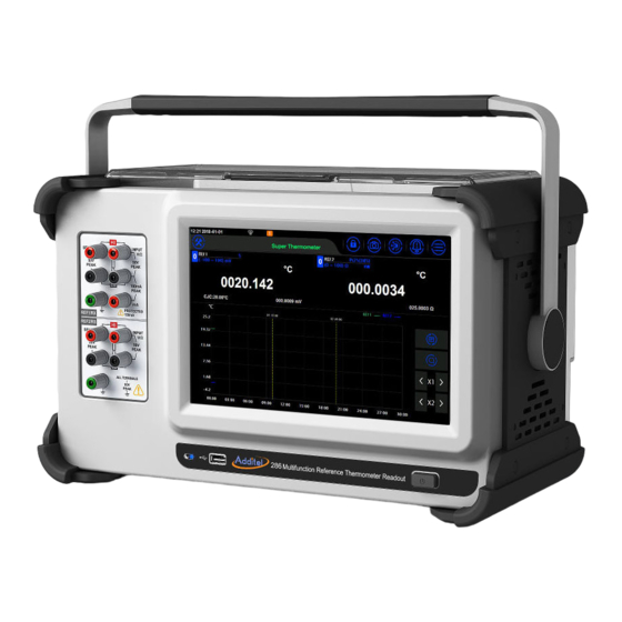
Introduction 1.1 General Introduction The ADT286 Multifunction Reference Thermometer Readout is the latest generation of intelligent advanced thermometer introduced by Additel, It adopts advanced high-precision electric measurement technology and interconnected multimedia interactive technologyideal for temperature calibration, mulit-channel temperature measurement, temperature and humidity filed testing, DMM and other functions which provides users with the high temperature measurement accuracy, flexible configurations, easy probe wiring, channel expansion, and a portable interactive experience. -
Page 16: Product Overview
Contact us Tel: +714-998-6899 www.additel.com 1.2 Product Overview Functions: Item Purpose Thermometry Bridge Ratio measurements Multichannel Thermometer Single or multi-channel measurements Data acquisition DC digital multimeter Smart Connection Remote wiring connections Probe Calibration Calibration and characterizations of various probe types... - Page 17 Thermal Calculator Signal calculation for various sensor types Intelligent communication of temperature Sources Control and interface with various temperature sources Sensor Library Stores specific information on reference sensors and devices under test ADT286 system component list, for details, seeing the sheet:...
- Page 18 Sheet 1: ADT286 system component list Type Name Description Shown Picture 8.5 digit DMM, which can measure RTD, thermocouple, thermistor, DC voltage, DC Multifunction Reference current and DC resistance. The front panel is ADT286 equipped with 2 standard channels. One...
- Page 19 DSUB-10M and/or process scanner scannerImproves measurement performance DG01 Scanner cover by reducing environmental impacts This adapter is used to provide the ADP27V 27V power adaptor ADT286-PS with a loop power supply for temperature transmitter measurements.
-
Page 20: Base Structure
1.3 Base Structure Picture 1 ADT286 Mainframe... - Page 21 Sheet 1 the component of ADT286 Mainframe Name Explanation Handle Handle can be rotated to various positions Front input terminals 2-channel measurement USB-A USB port used for data export and system updates Indicator Light To indicate that the thermometer is in standby or not.
- Page 22 Picture 2 Connection of inserting and unplugging of embedded scanners...
-
Page 23: Adt286-Ts Multi-Channel Temperature Signal Scanner
1.3.1 ADT286-TS Multi-channel temperature signal scanner Picture 3 Temperature Device... - Page 24 To indicate the scanner is receiving power and if it is cascaded to lamp another scanner The embedded connection port Port that connects on top of the ADT286 mainframe Cascade output For cascading next level Cascade input For cascading upper level...
-
Page 25: Adt286-Ps Multi-Channel Process Signal Scanner
1.3.2 ADT286-PS Multi-channel process signal scanner Picture 4 Process Device... - Page 26 To indicate the scanner is receiving power and if it is cascaded to another status indicator lamp scanner The embedded connection port Port that connects on top of the ADT286 mainframe Output port For cascading next level ○ 7 Input port For cascading upper level ○...
-
Page 27: Adt286-Dock Remote Intelligent Wiring Device
1.3.3 ADT286-Dock Remote intelligent wiring device Picture 5 Remote intelligent wiring device... - Page 28 Sheet 4 Remote intelligent wiring device Name explanation Scanner cover Protects scanner from environmental conditions ADT286-TS/PS signal scanner Scanner The signals of one channel wiring terminal in device will be Amphenol connector transferred to this terminal. The signals of one channel wiring terminal in device will be Amphenol connector transferred to this terminal.
-
Page 29: Adt280-25R/100R Standard Resistor
1.3.4 ADT280-25R/100R Standard Resistor Picture 6 This Standard Resistor is inserted into REF2 channel. Picture 6 Standard Resistor... -
Page 30: Connection Of Adt286-Ts/Ps
Sheet 5 Standard Resistor Name Explanation Resistance plug Wiring plug Resistance label With QR code, resistance Value, types and other information. 1.3.5 Connection of ADT286-TS/PS Picture 7 wiring connection... -
Page 31: Features
1.4 Features Precision temperature measurement and 8.5 digit DMM DC measurement Scanning speed is selectable: fast (10 channels/second), medium speed (1 channel/second), and slow speed (1 channel/4 seconds) The two standard channels on the front panel. To further improve the measurement accuracy, the REF1 channel can be connected to the SPRT, the REF2 can be connected to the external standard resistor, adopting the RX/RS resistance ratio measurement mode ... -
Page 32: Adt286-Ts Multi-Channel Temperature Signal Scanner
DC resistance Channel number: 2 –wire (DUT) for 20 channels ,3/4- wire (DUT) for 10 channels The scanner can be directly embedded on top of the ADT286 main unit or it can be cascaded with other signal scanners ... -
Page 33: Adt286-Ps Multi-Channel Process Signal Scanner
9-channel temperature switch simultaneously; Channel 1 is a standard channel, which can be connected to a standard SPRT or standard thermocouple ; This scanner can be directly embedded into ADT286 main unit, or it can be cascaded with other signal scanner... -
Page 34: Adt286-Dock Remote Intelligent Wiring Device
The main purpose of the device is to assist with wiring, verification of channel switching, and current channel monitoring Before the verification test starts, the remote ADT286 main unit automatically sends the detected information to the display of the device. The user finds the corresponding DUT according to prompted information on the screen and quickly finishes wiring. -
Page 35: Adt280-25R/100R Standard Resistance
1.4.4 ADT280-25R/100R Standard Resistor This resistor is mainly used for the RX/RS resistance ratio measurement mode of REF2 channel on two front panel of ADT286 To provide resistance values of 25Ω and 100Ω Simply insert into the front panel 1.5 Service Environment... -
Page 36: Technical Specification
1.6 Technical Specification 1. General Technical Index Sheet 7 Genenral Technical Index Type ADT286 Size 420mm(W) X 250mm(H) X 200mm(D) Weight 8.4kg ●Supply Require AC voltage shifting pulley 100V/120V/220V/240V;●36Wmax;●47Hz-440Hz Power Supply Requirement Screen Specification 10.1 inch TFT color screen, capacitive touch screen Communication Interface USB-A、USB-B、LAN、WIFI、Bluetooth... - Page 37 Channel capability Front panel: two 3/4- wire channels; embedded scanner: one ; external cascade scanner: three;Temperature signal scanner: 3/4 –wire for 10 channels or 2-wire for 20 channels; Electrical Specifications1 hour Warm-Up Time Process signal scanner: 1 standard reference channel, 9 transmitters or switch channels; Environment Temperature (18~28) °...
- Page 38 PRT Accuracy Rating of Resistance ADT286 Resolution 24hours 90days 1year Scanning Excitation Temperature Range Ratio speed (23 ±1) ° ° C (23 ± 5) ° ° C (23 ± 5) ° ° C current Coefficient 15ppm 0.01 mΩ 3 ppm or 0.2 mΩ...
- Page 39 * Automatic current reversal. PRT Accuracy Rating of Temperature ADT286 Temperature Scanning 24 Hour / ° C 90 Days / ° C 1 year / ° C Temperature Coefficient Speed (23 ±1) ° ° C (23 ± 5) ° ° C (23 ±...
- Page 40 SPRT RX/RS Mode Resistance Ratio Accuracy (Front Panel Channel REF1/RX,REF2/RS) 1 Year (23 ± 5) ° ° C Range Reference Resistance Ratio (Rx/Rs) ppm of Reading 2.00-4.00 1.10-2.00 0.85 100 Ω 25 Ω 0.90-1.10 0.50-0.90 0.25-0.50 2.00-4.00 1.10-2.00 0.81 400 Ω...
- Page 41 SPRT/PRT Measurement Accuracy using External Rs External Equivalent to SPRT/PRT Temperature Resistance 1 Year(23 ± 5)° C Reference Temperature Type (° C) Ratio (Rx/Rs) ppm of reading Resistance (mK) -189.3442 0.22 0.13 -38.8344 0.84 0.32 0.01 0.15 25 Ω PT25 231.928 1.89...
- Page 42 Thermistor Accuracy Measureme Scanning 24 Hour 90 Days 1 year Excitation Temperature Resolution nt Range Speed Coefficient (23 ±1) ° ° C (23 ± 5) ° C (23 ± 5) ° ° C Currert 1 mΩ 10 ppm or 60 mΩ 30 ppm or 80 mΩ...
- Page 43 Thermistor Temperature Accuracy Scanning 24 Hour / ° C 90 Days / ° C 1 year / ° C Type Temperature Speed (23 ±1)° C (23 ± 5) ° C (23 ± 5)° ° C -40 ° C 0.0007 0.0011 0.0014 0 °...
- Page 44 Thermistor Accuracy Test Scanning 24 hours 90 days 1 year Input Temperature Resolution Range Speed Resistance Coefficient (23 ±1) ° C (23 ±5) ° C (23 ±5) ° C Slow 5 ppm + 2 10 ppm + 14 ppm + 0.01 µV Speed 4 ppm...
- Page 45 Thermocouple Temperature Accuracy 24Hours/℃ 90Days/℃ 1Year/℃ (23± 1℃) (23± 5℃) (23± 5℃) Temperature Type Fast Medium Slow Fast Medium Slow Fast Medium Slow Speed Speed Speed Speed Speed Speed Speed Speed Speed -200 0.089 0.038 0.022 0.099 0.047 0.031 0.100 0.049 0.033...
- Page 46 0.056 0.023 0.013 0.061 0.028 0.018 0.061 0.028 0.018 0.056 0.023 0.013 0.061 0.029 0.019 0.062 0.030 0.020 0.054 0.023 0.014 0.061 0.030 0.020 0.062 0.031 0.021 0.055 0.025 0.015 0.063 0.033 0.023 0.066 0.035 0.026 1372 0.073 0.035 0.023 0.087 0.049 0.037...
- Page 47 0.619 0.254 0.141 0.676 0.311 0.198 0.676 0.311 0.199 0.342 0.141 0.079 0.374 0.173 0.111 0.375 0.175 0.113 1820 0.199 0.085 0.050 0.222 0.108 0.073 0.227 0.113 0.078 -200 0.224 0.093 0.052 0.246 0.115 0.075 0.247 0.116 0.076 -100 0.106 0.044 0.024 0.116...
- Page 48 0.045 0.019 0.011 0.049 0.023 0.015 0.050 0.024 0.016 0.037 0.016 0.010 0.042 0.021 0.014 0.043 0.022 0.016 0.034 0.015 0.010 0.039 0.021 0.015 0.041 0.023 0.017 *The index is based on the accuracy of the thermocouple electrical measurement of temperature scanner module, does not include the accuracy of the thermocouple itself and the fixed cold junction compensation at 0 °...
- Page 49 Medium 8 ppm + 14 ppm + 1 µV 2 ppm + 0.35 ppm Speed 0.38 ppm 0.38 ppm 2.6 ppm + 1.05 8.6 ppm + 14.6 ppm + Fast Speed 10 µV 1.08 ppm 1.08 ppm 32 ppm + 1 38 ppm + 1 Slow Speed 10 µV...
- Page 50 DC Current Accuracy 24 hours 90 days 1 year Burden Test Range Scanning Speed Resolution (23 ±1) ° C (23 ± 5) ° C (23 ±5) ° C Voltage Slow Speed 0.01 nA 15 ppm + 3 ppm 50 ppm + 6 ppm (-100-100) µA <1 mV 8 ppm + 0.1 nA...
- Page 51 24 hours 90 days 1 year Excitation Temperature Test Range Scanning Speed Resolution Current Coefficient (23 ±1)° C (23 ±5) ° C (23 ±5) ° C 13 ppm + 1.5 16 ppm + 1.5 0.01 mΩ Slow Speed 3 ppm + 1 ppm (0-100) Ω...
- Page 52 30 ppm + 1 40 ppm + 1 0.1 Ω Slow Speed 10 ppm + 0.6 ppm (0-1) MΩ 30 ppm + 0.6 40 ppm + 0.6 0.1 Ω 5 ppm + 0.2 Ω Medium Speed 10 ppm + 1.2 ppm 10 µA 30 ppm + 3 40 ppm + 3...
-
Page 53: Change Fuse
1.7 Fuses If to change the fuse, please confirm the right specification parameters of fuse (seeing the sheet) Sheet 6 Fuse Specification 90V-110V or 108V-132V 、198V-242V or 216V-264V , (47-440)Hz Power Supply Requirement Power Dissipation 40VA peak (30Watt average) Fuse specification 110V:0.315A F 250V 230V:0.315A F 250V The whole machine outages, then replace the fuse according to the following instruction. -
Page 54: 二、Display And Function Operation
Sheet 7 Fuse Serial NO. Name Explanation Voltage selector Rotate to select the correct voltage Fuse holder The fuse is installed in it Protective cover Fuse cover Display and Function Operation 2.1 Main Interface Display The default main interface consists of three parts: status bar, tool bar and main menu of single channel thermometer 2.1.1 Status Bar The top part of the display provides the information including:... -
Page 55: Menu Function Zone
2. Wi-Fi: The display icon indicates the Wi-Fi connection status and signal strength 3. USB: The display icon indicates that an USB device is inserted 4. Bluetooth: The display icon indicates that the Bluetooth function of thermometer is enabled 5. The insertion status of scanner and the number of inserted scanners. The status is represented by three colors, the orange icon indicates that the connection is abnormal;... -
Page 56: Main Menu
the red flashes, it indicates that the system has an abnormality or a fault has occurred. 2.1.3 Main Menu Click the button to open function menu and enter the following functions : Thermometry Bridge: Precision measurements on REF1 and REF2. Used for ratio measurements to an external resistor connected to REF2. - Page 57 (ADT286-DOCK). The user follows the prompt information on the screen of wiring device to find the corresponding channel and DUT to finish the wiring and judges whether the wiring is correct according to the detected value displayed on the screen. If the wiring is correct, the user switches to the next channel and DUT for wiring on the remote intelligent wiring device.
-
Page 58: Multi-Channel Thermometer
2.2 MultiChannel Thermometer The function of multi-channel thermometer is to make continuous measurements for single channel numerically or graphically, and switching of channels manually or automatically. The default main interface displays the current scanning channel, measuring type, measuring range, measured value, scanning speed, and smoothing and other information. -
Page 59: Channel Switch
Picture10 Multi-channel thermometer (graphical display) 2.2.1 Channel Switch Manually Switchover: Click the left and right direction buttons to switch the measuring channel, or... - Page 60 click the current measuring channel button to select the channel to be switched. Automatically Scanning: Click to set automatically scanning by time our count. After settings are complete, click to begin automatically scanning, and the automatically scanning function will begin to scan all online channels based on user’s settings.
-
Page 61: Channel Settings
2.2.3 Channel Settings Click the Settings button to select the channel settings menu, then enter the channel settings interface. The top tab of the interface will display all the scanners currently connected to the thermometer (including the front panel channel), click the scanner label to switch to the channel list of the scanner. Sheet 8 channel settings of front panel Design item Operation... - Page 62 Improving measurement accuracy small-range voltage High Resistance ON/OFF measurements Open Circuit Detect ON/OFF Settings the "thermocouple" connection is normal or not External will use the temperature of the fixed value. Custom CJC will use the reading of the other channel to be the CJC value for the thermocouple being measured.
- Page 63 Sheet 9 channel settings of temperature scanner Settings Operation Explanation Enabled ON/OFF Whether to display the measurement data Label Label Customizable naming for the measurement channel Including voltage, resistance, TC, standard TC, RTD, SPRT, Custom Function Function setting RTD, Thermistor The time it takes to switch from the other channel to the current Fixed delay/Extra delay Manually input (0~60000)ms...
- Page 64 the SPRT measurement as the CJC. Cold junction type is fixed value display, the default cold junction Cold Junction fixed Value Manually input(-20-100)℃ value is 0 d.em, the 1 has a Type S TC(-20-100)c Wiring length Manually input(0-50)m Set the wiring length of sensor Channel Settings of Process Scanner The channel settings of process scanner differs from the other channel settings in that during the measurement of process scanner, the channel 1 is typically used to measure a reference standardand other channels are as...
-
Page 65: Front Panel
channel Wiring system 2-, 3-, or 4-wire 2-, 3-, or 4-wire configurations for each channel Sensor type Humidity sensor, pressure sensor When in channel of 02~10, the sensor types can be selected. Internal will use the interal CJC temperature measurement. External CJC Type Internal/External will use the temperature of the fixed value. -
Page 66: Display Settings
Click to enter temperature scanner settings. All channel settings are the same as the channel set up except for the “Apply to channels” and “CJC Channel.” Apply to all channels allows for the current settings to be applied to the selected channels. CJC Channel designats a channel for the CJC measurement when another channel has CJC Type set to Custom. -
Page 67: Scanner
Filter: It can be manually input (1~999) to filter the data Graph types: select lin chart or a scatter chart 1.2.5 Graph Display The multi-channel thermometer support chart display mode (seeing picture 10) The Graph icon provides switching function between the numeric display mode and the graph display mode. The icon provides the function of clearing historical data. -
Page 68: Channel Settings
Scan count: Set the scan amount for the test. Scan count of 2 means that all channels on the scan list will be scanned twice to complete the test. Scanning list: you can add and delete channels that need to be scanned. ... - Page 69 2.3.4 Display settings Display settings are the same as 2.2.4 display setting of single-channel thermometer; 2.3.5 How to use Click the Start button on the right toolbar to scan the selected channels. When a data logging session is started there are various view for the display: Data, Chart, Monitor, and Info. Each view can be selected on the right vertical tool bar.
- Page 70 2.4 Thermometery Bridge Select Thermometery Bridge in the main menu to access the thermometery bridge function. The front panel of the thermometer Main Unit provides two standard temperature measurement channels, REF1 and REF2. In this application, the user can access two standard sensors to achieve high precision temperature measurement. 2.4.1 Channel Settings ...
- Page 71 thermometer will use the RX/RS ratio measurement mode, and REF2 needs to access the standard resistor; Thermocouple break test: Check if the thermocouple is disconnected or not Cold junction type: fixed and custom Fixed value of Cold junction : the default is 0 ° C, the settings can be manually input in (-20~100) ° C ...
- Page 72 1) Use a ice-point reference as the external cold junction compensation, at which two thermocouples can be connected; 2) The REF1 channel is connected to a thermocouple, and the REF2 channel is connected to a SPRT for the cold junction measurement of the thermocouple.. REF2 needs to be set up as the CJC channel by selecting channel settings in the multi-channel thermometer menu, then select and set REF2 as the CJC.
-
Page 73: Smart Connection
Picture 12 Smart Connection Interface Before the test starts, the user edits the configuration information of each channel on the ADT286 main unit. After editing the information of each channel is automatically sent to ADT286-Dock remote intelligent junction box, and... -
Page 74: Local Wiring
on the screen. If there is a problem with the wiring, the wiring problem can be found easily nearby; if the wiring is correct, the user can manually switch to the next channel and DUT on the remote smart wiring device for continuing wiring. - Page 75 4) The user finds the corresponding channel and the completed wiring according to the screen information of the ADT286-DOCK; The ADT286-DOCK screen can display the wiring information such as the measured range of the DUT, current channel and measurement data. After the user judges that the wiring is correct, click the next channel button of the external base to switch to the next channel to continue wiring, or press the previous channel button to view the wiring information of the previous channel;...
- Page 76 This application uses the front panel REF1 of thermometer as multimeter, the signals which can be measured are: DC voltage, DC current, DC resistance. Through clicking to open the measurement settings menu Click the button of measuring setting menu to close the menu display. The display change icon provides switching between the numerica and graphical display mode, and the reset icon...
- Page 77 Sheet 11 Measurement settings menu Function Explanation Voltage Current Resistance Automatically select the range ● ● ● Auto based on the reading The sampling speed is optional ● ● ● Sampling speed in slow /medium/fast ● ● ● Display digits Display resolution.
- Page 78 2.6.1 DC Voltage Measurement Range: Auto: 100mV,1V,10V,50V Support high OFFSET User selectable filtering Supports fast/medium/slow sampling speeds Supports 6/7/8/9 display resolution 2.6.2 DCI Current Measurement Range: Auto:100uA,1mA,10mA,100mA; OFFSET User selectable filtering ...
- Page 79 2.6.3 Two- wire resistance measurement Range: Auto:100Ω,1kΩ,10kΩ,100kΩ,1MΩ,10MΩ,100MΩ OFFSET User selectable filtering Support fast/medium/slow sampling speeds Support 6/7/8/9 display resolution 2.6.4 Four-wire resistance measurement Range: Auto:100Ω,1kΩ,10kΩ,100kΩ,1MΩ,10MΩ,100MΩ OFFSET User selectable filtering Current reversal ...
- Page 80 2.7 Temperature Source Management The temperature source management interface can be accessed through the button in the menu function area. When the number is displayed in the lower right corner of the temperature source button, it indicates the number of the current connected temperature source (as shown, it indicates that one temperature source is currently connected).
- Page 81 type. Automatically configure the communication mode as network communication or serial communication, and complete the configuration according to the specific information (IP address, port number of network communication, or Baud rate, parity bit, data bit and stop bit for serial communication). Click button to get the basic information of temperature source.
-
Page 82: System Settings
userThe user can click on the button to add a custom temperature source type. The user can configure a customized temperature source type by configuring common settings, communication settings, and command settings. 3. Command communication tools The command communication tool can use the network or serial communication to establish a communication connection with the temperature source device to help the user to test the temperature source command. -
Page 83: Sensor Library
3.1 Date Protection Data protection includes password editing, password protections of sensor library, standard resistor, data management and system services. Passwords can be entered and modified for various fields. 3.2 Sensor Library The sensor library offers eight sensor types: TC, standard TC, RTD, SPRT, custom RTD, thermistor, humidity transducer, pressure and temperature transducers. -
Page 84: Industrial Thermal Resistance
Sheet 12 Standard Thermocouple Items Effective Value Explanation type name standard Type/Name Number, letter and Chinese, up to 14 digits input thermocouple Serial Number Number, letter and Chinese, up to 14 digits input The serial number of standard thermocouple Standard thermocouple temperature range, Temperature range Based on temperature unit unit switching by clicking temperature unit... -
Page 85: Standard Platinum Resistance
Pt500(385)、Pt1000(385)、Pt100(391)、Pt100(3916)、Pt100(3926)、Cu100(428)、Cu50(428)、Cu10(427)、 Ni100(617)、Ni100(618)、Ni120(672)、Ni1000; 3.2.4 Standard Platinum Resistance Thermometers (ITS-90 SPRTS) Users can add, edit, and delete ITS-90 SPRTs, which are displayed as a list when added. Sheet 13 Standard Platinum Resistance Parameter Setting Items Effective Value Explanation Type/Name Number, letter and Chinese, up to 14 digits Types and names Serial Number Number, letter and Chinese, up to 14 digits... - Page 86 3.2.5 Custom RTD The user can add, delete and modify the custom RTD. The custom RTD includes CVD equation and RTD. The RTD is the same as 3.2.3 Industrial RTD. The CVD equation is as follows:...
-
Page 87: Thermistor
Sheet 14 VCD equation Items Effective value Explanation Type/Name Number, letter and Chinese, up to 14 digits Types and names Serial Number Number, letter and Chinese, up to 14 digits Serial Number CVD equation temperature range, unit Temperature range Based on temperature unit switching by clicking temperature unit Digits Thermal resistance R0 value... - Page 88 Sheet 15 Thermistor Items Effective Value Explanation Type/Name Number, letter and Chinese, up to 14 digits Type and name Serial Number Number, letter and Chinese, up to 14 digits Serial Number Upper lower limit temperature Temperature range The default is C, switchable (-273.15~9999)℃, the default is (-80~150)℃...
-
Page 89: Humidity Sensor
3.2.7 Humidity Sensor The user can add, delete and modify the humidity sensor, seeing the following sheet: Sheet 16 Humidity Sensor Items Effective value Explanation Type/Name Number, letter and Chinese, up to 14 digits Type and name Serial Number Number, letter and Chinese, up to 14 digits Serial Number Transfer function Linear/ Square Root... -
Page 90: Pressure Sensor
3.2.8 Pressure Sensor The user can add, delete and modify the pressure sensor information. The specific operation is the same as sheet 19 except related to pressure units. 3.2.9 Temperature Transducer The user can add, delete and revise temperature transducer, operation the same as sheet 19 of humidity sensor except units are in relation to temperature. -
Page 91: Communication Setting
Sheet 17 Standard Resistor Library Items Effective Value Explanation Name and type of standard Number, letter and Chinese, up to 14 digits Name and type Serial Number Number, letter and Chinese, up to 14 digits Serial Number R(Ω ) digit Certificate value of standard resistor Calibration date 2000/1/1~2099/12/31... -
Page 92: Ethernet
3.4.1 Ethernet Connect the device and the host computer through the network cable. Sheet 18Ethernet address methodsEthernet address methods Items Effective value Explanation Choose the way to access the Address access DHCP/ Manually device address When the DHCP mode is selected, the contents of the following sheet are automatically assigned by the system and become read-only items. - Page 93 Sheet 19 The Ethernet address is set manually Items Effective value Explanation IP address 0.0.0.0 ~ 255.255.255.255 Set IP address of thermometer Subnet mask 0.0.0.0 ~ 255.255.255.255 Set Subnet mask of thermometer Gateway 0.0.0.0 ~ 255.255.255.255 Set source gateway of thermometer ...
- Page 94 Sheet 20 Wi-Fi communication settings Items Effective value Explanation WLAN Open/Close Open/close Wireless network Based on network environment Wireless network access point selection Advanced options DHCP/ manually Choose the ways to access the device address The port number and physical address are factory settings and cannot be changed. 1.
-
Page 95: Wireless Communication
Sheet 21 Wireless communication manually settings Items Effective value Explanation IP Address 0.0.0.0 ~ 255.255.255.255 Set IP address of device Subnet mask 0.0.0.0 ~ 255.255.255.255 Set subnet mask of device Gateway 0.0.0.0 ~ 255.255.255.255 Set gateway of device Click right corner of screen to confirm the settings;... -
Page 96: Date And Time
3.5.1 Date and Time Sheet 22 Date and Time Items Effective value Explanation Time 00:00 ~ 23:59 Time settings Date 2000-1-1 ~ 2099-12-31 Date settings Date format Year-month-day/ month-day-year/day-month-year Date format settings Separator -,/,. Date separator settings 3.5.2 Language The device provides a multi-language interface that allows you to select an available language interface ... -
Page 97: Sound
3.5.3 Sound Sheet 23 Sound Settings Items Effective value Explanation keypad tone ON/OFF keypad tone settings Warning tone ON/OFF Warning tone settings 3.5.4 Screen Contrast Click the progress bar to slide left or right to adjust the screen brightness. 3.6 System Service System services include system calibration, maintenance, factory reset, and system upgrades. - Page 98 security Click the button to clear users’ calibration data and restor the factory settings 3.6.1.1 Voltage Calibration Four ranges: (-100~100)mV、(-1~1)V、(-10~10)V、(-50~50)V; Click the button to clean calibration data of voltage user for restoring factory calibration Choosing the range item which needs to be calibrated to enter calibration interface ...
- Page 99 3 After the calibration of all calibration points is completed, click to save calibration data. 3.6.1.2 Current Calibration Four ranges: (-100~100)uA、(-1~1) mA、(-10~10) mA、(-100~100)mA Click the button to clear calibration data and restor the factory calibration Choose the range which needs to be calibrated to enter calibration interface ...
- Page 100 3 After the calibration of all calibration points is completed, click to save the calibration data. 3.6.1.3 Resistance Calibration Seven ranges: (0~100)Ω、(0~1)kr、(0~10)ka、(0~100)kn、(0~1)M)、(0~10)Mk、(0~100)Mn (Including the calibration of resistance, thermal resistance and thermistor) Click the button to clear calibration data of resistance and restore the factory calibration ...
-
Page 101: Maintenance
scanner Channel 1. Calibration Process: 1. Cold junction calibration uses type E thermocouples by default, click sensor type to select other types 2. When the temperature is stable, please click the standard value text box to input the current standard temperature 3. -
Page 102: Factory Settings Data Reset
Upgrade operation 1. Copy the upgrade file to the root directory of the USB flash drive. This file can be found at www.additel.com 2. After booting, insert the USB flash drive into the USB port on the front of the thermometer... -
Page 103: System Information
3. Enter the system upgrade interface, select the upgrade package and start upgrading 4. Click until the system starts to automatically upgrade 5. Wait a few minutes, after the upgrade process is completed, the system will automatically display the upgrade completion information. -
Page 104: Operation Information
Provide file search function to find files according to time, file name, operator and other information. 3.9 Acloud Service Provide Ethernet wired and Wi-Fi wireless communication to access Acloud services. Users can monitor the real-time running status and data of the device anytime and anywhere through Additel Link (providing mobile... -
Page 105: Application
phone APP, PC and other client methods). Sheet 24 Acloud Service Explanation Items Effective value Start using Open/Close Open or close Acloud service function When the Acloud service is opened, the upper status bar of thermometer interface will show the staring icon of Acloud service. -
Page 106: Display Settings
The main screen displays tests that have previously been created.Click to delete the created test plan(s). Click to enter menus for Data Management and Display Settings. 4.1.1 Data Management Seeing section 3.8 Data Management 4.1.2 Display Settings Temperature unit: K, °... -
Page 107: Operation Process
4.1.3 Operation Process 1) PRT calibration 1. Click to enter the interface of DUT type, and select PRT 2. Select the reference prob and the channel it will be associated with. The reference probe is selected from the sensor library. 3. - Page 108 needs to be before measurements can be made. Stability time: time fram over which the stability tolerance must be meet. Additonal waiting time: additional time for stabilization Channel scan cycles: number of times all channels are scanned ...
- Page 109 9. After completing all the set point select to enter the save interface to the internal memory of the ADT286. Click the list of DUT sensors on the left to view the corresponding test results. Click to select the set point used for SPRT or CVD coefficient calculation and edit coefficient calculation for thermal resistance.
- Page 110 range is unified), and the external standard resistor of the REF2 channel can also be set. 3. Click to enter the fixed point editing page. The user can click on a set point to edit and modify the fixed point temperature, pre-wait time, stability, stability time and other information. The users can also add, delete fixed points and adjust the fixed point order as needed.
- Page 111 If all the tests under the current fixed point are completed, it will return to the previous interface to select another fixed point or DUT to continue testing. 8. When all test points of all DUT are finished, Click to enter the save interface. Click to modify the set point used to calculate the coefficient.
-
Page 112: Environmental Temperature Field Test
4) Standard thermocouple calibration: The calibration of standard thermocouple is as same the calibration of thermocouple, but only the S or B couple can be selected as DUT. 5) Thermistor calibration: The thermistor calibration process can refer to the platinum RTD calibration process, no coefficient calculation, no standard resistance function. -
Page 113: Operation Procedure
4.2.1 Operation Procedure 1) Create a new test. Select the sensor types at the top of the interface for temperature and humidity. The test plan provides upper, middle and lower test points. It supports up to 15 temperature points and 4 humidity points. -
Page 114: Display Settings
4.2.3 Display Settings The display settings are the same as those shown in 4.1.3 Sensor Test Display Settings. 4.3 Switch Test The process scanner is required for the switch test. 4.3.1 Switch Test Settings 1) Function box: select the function box 2) Function: select standard sensor 3) Connections: select reference sensorand wire configurations. -
Page 115: Switch Test Process
7) Sampling speed: fast, medium and slow speed. 8) Recording times: set the number of records, manually input. 9) Temperature source: Select a temperature source to connect. 4.3.2 Switch Test Process After setting, click the Save button in the lower right corner to enter the switch test page for switch test. 1) The CH1-01 channel of the process scanner is used to measure the reference sensor and other channels are for the DUTs. -
Page 116: Stability Test
4.4 The Performance Test of Constant Temperature Source The constant temperature source performance test includes stability test and various axial and radial uniformity tests 4.4.1 Stability Test Test the stability of the dry well temperature over time. 1. Test Settings ... -
Page 117: Dry Well Radial Uniformity Test
4. Stability test procedure The scan data is displayed graphically or numerically. You can click to switch, click to reset the current test data, and click to save the data after the test is completed, ( this button can be used to expand the screenshot of two yellow wires in the chart). - Page 118 3. Add Temperature Source 4. Test Process After the temperature is stable, click for the reading, then change the measurement position of the two sensors, read it again after stabilization, repeat the above steps until four readings are made and finally find temperature difference value among holes according to the formula.
-
Page 119: Bath Uniformity Test
2. Data Management See 3.8 data management. 3. Add Temperature Source 4. Test Process Place the sensors according to the screen prompts for installation positions, after it is stable, click to take the reading, then move the sensor position for the next reading. After all readings are made click to save the test record. -
Page 120: Furnace Radial Uniformitytest
See 3.8 data management. 3. Add Temperature Source 4. Test Process Insert the two thermometers vertically into the temperature field and install them at A and O points, after the temperature is stable, click for reading repeat these steps 4 times. ... -
Page 121: Dry Well Axial Uniformity Test
See 3.8 data management. 3. Add Temperature Source 4. Test Process Select the test settings and configure the reference sensor and the moving sensor. Record temperature values two times for all position points, then click to save the results. 4.4.6 Furnace axial uniformity test 1. - Page 122 into the center test positioning tube, move between points from -5 to +5, when the furnace temperature is set in the test. At the temperature point, when the furnace temperature stability meets the specified requirements, to read and when all points’ reading, please click click for save.
-
Page 123: How To Set
4.5.1 How to Set Users can click the Settings button in the lower right corner of the menu bar to perform screenshot management "Settings" Sheet 25 Screen shot Explanation Item Effective value Storage path Local/ U flash disk Select the storage position for screenshot files Storage quantity (only can selecting a Number of screenshots which can be saved in a Read only... -
Page 124: Snapshot
4.5.3 How to Check 1) The initial screen in this application lists all snapshots stored. On this page, the user clicks the button on the right toolbar to delete all screen capture files. Click the button to export the screen capture file to the specified folder of the USB flash drive. -
Page 125: Thermo Technical Calculator
4.6 Thermo Technical Calculator The thermal technical calculator provides thermocouple and thermal resistance calculation functions, and also provides SPRT coefficient value calculation, which is convenient for users to perform unit numerical conversion on site. 4.6.1 How to Set 1. TC:... - Page 126 Sheet 26 Thermo Technical Calculator of TC Items Effective value Explanation S、R、B、K、N、E、J、T、C、D、G、 Sensor types Select the types of TC L、U、LR、A、10nsor、1mV/o Thermocouple electrical signal output in mV Electrical signal Based on the types of couplet selected If you need to calculate the electrical signal value, please enter the cold junction fixed value first.
- Page 127 degrees Fahrenheit and 293.15 Kelvin corresponding to 20 centigrade degree and electrical signal value can be calculated based on current cold junction fixed value. 2. Thermal Resistance Sheet 27 Thermotechnical Calculator of Thermal Resistance Item Effective value Explanation RTD, Custom RTD, ITS-90 (SPRT) and Sensor types Select thermal resistance types thermistor...
-
Page 128: How To Use
a11(0~29.7646) W(Ga) a5、b5(-38.8433~29.7646) W(Ga)、W(Hg) a4、b4(-189.3442~0.01) W(Hg)、W(Ar) 4.6.2 How to Use The user only needs to click the known items and input the value, the thermometer will automatically calculate the value of the remaining items.
Need help?
Do you have a question about the ADT286 and is the answer not in the manual?
Questions and answers