Table of Contents
Advertisement
Quick Links
Advertisement
Table of Contents

Subscribe to Our Youtube Channel
Related Manuals for Additel 686


Summary of Contents for Additel 686
- Page 1 686 Advanced Digital Pressure Gauge 673 Advanced Digital Pressure Calibrator...
- Page 3 · ADT686 Advanced Digital Pressure Gauge ADT673 Advanced Digital Pressure Calibrator -------User Manual [Version:2108V01] Additel Corporation...
- Page 4 This user manual provides operating and safety instructions for the ADT686 Advanced Digital Pressure Gauge and ADT673 Advanced Digital Pressure Calibrator. To ensure correct operation and safety, please follow the instructions in this manual. Additel Corporation reserves the right to change the contents and other information contained in this manual without notice.
-
Page 5: Table Of Contents
CONTENT Content ....................................I Safety Instructions ................................1 1. Introduction ................................... 2 1.1 Overview ..................................2 1.2 Pressure Range and Accuracy ........................... 3 1.3 Specification ................................8 1.4 Characteristics ......................E RROR OOKMARK NOT DEFINED 1.5 Basic Structure ................................. 11 2. - Page 6 2.4.2 Zeroing ................................22 2.4.3 Scaling ................................22 2.4.4 Filtering ................................22 2.4.5 Statistics ................................23 2.5 Intelligent HART Calibration(Only support ADT673) ..................23 3. Setting ..................................30 3.1 Communication Setting ............................31 3.1.1 Bluetooth ................................31 3.1.2 Wireless Communication ........................... 31 3.1.3 Serial Communication ............................
- Page 7 3.3.2 Repair and Maintenance ........................... 39 3.3.3 Restore Factory Settings ........................... 39 3.3.4 System Update ..............................39 3.4 Power Management ..............................40 3.4.1 Display Brightness ............................. 40 3.4.2 Battary Information ............................40 3.4.3 Auto Backlight Off .............................. 40 3.4.4 Auto Power Off After Backlight Off ........................40 3.4.5 Charge Mode ..............................
- Page 8 8.2 HART Communicator Operation ..........................55 9. Copyright ..................................56 Appendix A:Description of RS232 module DB9 pins....................56 Appendix B: Description for Type-C to USB female OTG adapter ................58...
-
Page 9: Safety Instructions
In order to avoid damaging the digital pressure gauge, please follow the user manual. To prevent possible damage of the product, please: ◆ Do not use the product under strong mechanical vibration environment; ◆ Do not use the product if it appears to have any issues, and contact Additel immediately... -
Page 10: Introduction
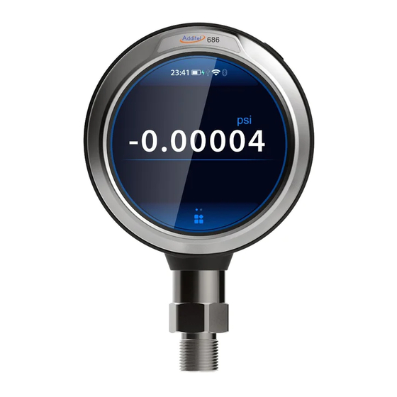
ADT686 Advanced Digital Pressure Gauge/ ADT673 Advanced Digital Pressure Calibrator are the newest generation of Additel pressure calibration products. They are excellent calibration and measurement devices.. These units have pioneered the use of a circular TFT-LCD capacitive touch screen and an easy-to-use interface. ADT673 Advanced Digital Pressure Calibrator can be easily used to perform the calibration of pressure transmitters, pressure switches, precision pressure gauges, general pressure gauges, sphygmomanometers, pressure sensors, etc., and can... -
Page 11: Pressure Range And Accuracy
1.2 Pressure Ranges and Accuracy Table 1 Gauge pressure Pressure Range Accuracy Media Burst Pressure (psi) (bar) -1.0 0.02 (0.05) 0.16 0.05 0.35 0.05 GP10 0.02 (0.05) GP15 0.02 (0.05) GP30 0.02 (0.05) GP50 0.02 (0.05) GP100 0.02 (0.05) GP150 0.02 (0.05) GP300 0.02 (0.05) - Page 12 GP2K 2,000 0.02 (0.05) GP3K 3,000 0.02 (0.05) GP5K 5,000 0.02 (0.05) GP10K 10,000 0.02 (0.05) GP15K 15,000 1,000 0.05 (0.1) 1.5X GP20K 20,000 1,400 0.05 (0.1) 1.5X GP25K 25,000 1,600 0.05 (0.1) 1.5X GP30K 30,000 2,000 0.05 (0.1) 1.5X GP36K 36,000 2,500...
- Page 13 Table 2 Differential pressure Static Pressure Range Accuracy Media Burst Pressure Pressure (%FS) (inH2O) (mbar) Range ±1 ±2.5 0.05 100X ±10 psi ±2 ±5.0 0.05 100X ±10 psi ±5 ±10 0.05 ±10 psi DP10 ±10 ±25 0.05 ±10 psi DP20 ±20 ±50 0.05...
- Page 14 Table 3 Compound pressure Pressure Range Accuracy Media Burst Pressure (psi) (bar) ±2 ±0.16 0.05 ±5 ±0.35 0.02 (0.05) CP10 ±10 ±0.7 0.02 (0.05) CP15 ±15 ±1 0.02 (0.05) CP30 -15 to 30 -1 to 2 0.02 (0.05) CP100 -15 to 100 -1 to 7 0.02 (0.05) CP300...
- Page 15 Table 4 Absolute pressure Pressure Range Media Accuracy (%FS) Burst Pressure (psi) (bar) 0.35 AP10 AP15 AP30 AP50 AP100 0.05(0.1) AP300 0.05(0.1) AP500 0.05(0.1) AP1K 1000 0.05(0.1) AP3K 3000 0.05(0.1) AP5K 5000 0.05(0.1) [1] G=Gas, L=Liquid *Note ◆ Temperature Compensation:(-10~50)℃, 1year accuracy; ◆...
-
Page 16: Specification
1.3 Technical Specifications Table 5 Technical Specifications Protection level IP67 Pa, hPa,kPa, MPa, psi, bar, mbar, torr,gf/cm2,kgf/cm2,inH2O@4°C , inH2O@20°C , mmH2O@4°C , Pressure units mmH2O@20°C , ftH2O@4°C , ftH2O@4°C ,inHg@0°C , mmHg@0°C ,mtorr, Ib/ft2,tsi,psf, inH2O@68F, ftH2O@68F, Different pressure ranges have different units. Users can custom 5 pressure units. When the pressure measurement value exceeds 120% FS, the outer circle of the screen will turn red, and Pressure overload flash and the speaker sounds an alarm rhythmically... - Page 17 Display Circular TFT LCD capacitive touch screen 1. 6600mAh Lithium-ion rechargeable battery, power consumption around 2.5W Power supply 2. Special TYPE-C USB adapter for power supply, maximum charging current 2A (battery power for best accuracy); Charging Charging time is about 5 hours, provided by dedicated 5V adapter Battery life 24V power supply loading will affect the battery life.
- Page 18 The internal 250ΩHART resistance is switchable,three types of HART transmitter connections are Loop Transmitter supported: Measurement 1) offline calibration mode: internal power supply, internal resistance; 2) communicator: external power supply, external resistance; 3) online calibration mode: external power supply, internal resistance; 1.4 Features High accuracy pressure measurement, wide range temperature compensation;...
-
Page 19: Basic Structure
1.5 Basic Structure Figure 1 Basic Structure... - Page 20 Table 7 Main connections Introduction Comment ADT673 only, common, black V/mA/SW ADT673 only, voltage/circuit/switch measurement input, red and white Loop ADT673 only, DC power output, red Short press to turn on, press and hold for 2 seconds to turn off, short press to take Power a screenshot when it is turned on.
-
Page 21: Display And Operation
2 Display and Operation 2.1 Main Page There are three modes provided in main page: calibrator mode (only for ADT673), digital gauge mode and dial gauge mode, see the Figure 2. Figure 2 Three modes in main page Calibrator mode: upper is electrical channel, lower is pressure measurement channel, click each to enter the function menu of the corresponding channel (only ADT673 supports this mode). - Page 22 Dial gauge mode: The pressure value is displayed in the form of a dial pressure gauge, which is a more intuitive way to display the pressure value and changes. Each page is divided into three parts: status bar, content area, toolbar and pressure percentage indication. (1) Status bar: including time and date, Bluetooth, WIFI, USB status, ACloud service, battery status, adapter status, 24V status;...
-
Page 23: Control Center
2.2 Control Center Click on the status bar at the top of the interface to pop up the control center interface, as shown in Figure 3. The control center provides quick viewing of various commonly used information and shortcut operations Figure 3 Control Center : Time and date icon, showing the system date and time, click to modify the time and date;... - Page 24 : Internal temperature icon, which displays the ambient temperature in the device, click to modify the temperature unit. This function is used for compensation temperature and not process temperature. : Notification center icon, when there is an abnormal message notification, there will be a red dot on the icon to remind you, click to enter the notification center, and the received abnormal notification information will be displayed;...
-
Page 25: Pressure Measurement Function
2.3 Pressure Measurement Function Click on the pressure channel function area, and you can perform basic configuration of the pressure channel at this time, such as zeroing, filtering, and statistical functions. The interface display is shown in Figure 4. Figure 4 Pressure Measurement Function 2.3.1 Zeroing Zeroing:In gauge pressure mode, when the gauge is vented to the atmosphere, it provides a zeroing operation when the zero point is deviated to eliminate the measured zero-point drift. -
Page 26: Filtering
2.3.2 Statistics Click to open statistics function to view statistics and reset statistics. Table 8 Statistics Item Description Enabled Open statistics function Max value Min value Average value Reset statistics 2.3.3 Filtering Filtering: Provides first-order linear filtering and moving average filtering, and moving average filtering also provides settings for de-extreme value pairs Table 9 Filtering Item... -
Page 27: Unit Switch
filtering Number of de-extreme value pairs 0~10 Number of average filtering de- extreme pairs 2.3.4 Unit Switch Click to enter the pressure unit selection interface (as shown in Figure 5), you can choose the unit to change. Figure 5 Unit switch 2.3.5 Pressure Setting Click to enter the pressure setting interface to perform operations such as pressure type, readings number,... -
Page 28: Display Resolution Setting
Table 10 Pressure Settings Item Effective value Description Pressure type Gauge pressure/Absolute pressure Set pressure type Display Rate 1 ~ 10 Readings per second Stability enabled Open/ close Turn on stability judgment Stability ±(0.005~1)%F.S It can be set after turning on stability enabled Stability time (1 ~... -
Page 29: Electrical Measuremnt(Only For Adt673
2.4 Electrical Measurement(ADT673 only) Like pressure measurement, click the main value of the electrical measurement channel to enter the electrical measurement function setting interface, as shown in Figure 6. Figure 6 Electrical signal measurement function ◆ It is forbidden to apply current/voltage exceeding the current measuring range to the calibrator; ◆... -
Page 30: Measuring Item Switch
2.4.1 Measuring a Switch Four buttons can switch between current measurement, voltage measurement, switch test and HART communication. Switch test can choose switch type (mechanical switch, PNP and NPN electronic switch). When selecting the switch function, the latest switch type will be displayed. 2.4.2 Zeroing The current/voltage signal provides short-circuit zeroing operation to eliminate the measured zero drift. -
Page 31: Statistics
2.4.5 Statistics For specific operations, see 2.3.2. 2.5 Intelligent HART Calibration(ADT673 only) The calibrator supports HART communication, uses a simplified DD file to provide the setting, maintenance and calibration of common parameters for HART pressure transmitters. It is recommended to refer to the instruction manual of the transmitter before using the calibrator to operate the transmitter. - Page 32 1) The connection method of internal power supply and internal resistance is shown in Figure 7; Figure 7 HART-Internal power and internal resistance 2) The connection method of external power supply and internal resistance is shown in Figure 8; Figure 8 HART-External power and internal resistance 3) The connection method of external power supply and external resistance is shown in Figure 9;...
- Page 33 ◆ After selecting the power supply configuration, enter the search interface. Start searching for HART devices from address "0", if the search is successful at address "0", stop searching and display the HART device list and main information, otherwise the calibrator will start searching from address "1" until address "15", After finishing searching, the calibrator will list all the searched HART devices, and it can support up to 15 HART devices at the same time;...
- Page 34 ◆ When do a calibration task for a HART transmitter, select the HART process value to be calibrated. 4. Settings (1) Parameters ◆ In main operation page, switching into HART, then press to enter the HART parameters setting interface, seeing Table 12. Table 12 HART Parameters Item Parameters...
- Page 35 Device No. Read only parameter Writing protection Read only parameter Universal version Read only parameter Software version Read only parameter Hardware version Read only parameter Device version Read only parameter Sensor Sensor SN Read only parameter Sensor unit Read only parameter Sensor lower limit Read only parameter Sensor upper limit...
- Page 36 Burst mode It can be set to enable/disable, depending on whether the transmitter supports it. Burst command Burst command value can be set Alarm status Read-only parameter (2) Operation ◆ In the HART settings interface, you can view the HART parameter values in real time ◆...
- Page 37 transmitter is consistent with the actual output loop current; ◆ Provides adjustment of D/A zero point (4mA) and D/A gain (20mA): you can press the screen to get the current value for adjustment (4) Sensor trim Sensor trim is the adjustment of the PV process variable of the transmitter, which usually contains one or two adjustment points (low point and high point).
-
Page 38: Setting
After selecting "Restore Factory", a prompt will appear asking "Are you sure to restore the sensor factory calibration?” click on the screen to execute the factory restore command. After success, the transmitter's high and low point adjustment values will be restored to the factory adjustment state. 3 . -
Page 39: Communication Setting
3.1 Communication Setting 3.1.1 Bluetooth The calibrator communicates with the mobile phone App via Bluetooth. Table 13 Bluetooth communication setting Item Effective value Description Bluetooth state Open/close Open or close Bluetooth function Bluetooth name Support letters, numbers or symbols Set the Bluetooth name of the calibrator Physical address Read only 3.1.2 Wireless Communication... -
Page 40: Serial Communication
in manually: Table 15 Wireless communication manually setting Item Effective value Description IP Address 0.0.0.0 ~ 255.255.255.255 Set IP address of device Subnet mask 0.0.0.0 ~ 255.255.255.255 Set subnet mask of device Gateway 0.0.0.0 ~ 255.255.255.255 Set gateway of device (1) Click the button at the bottom right corner of the screen to confirm the settings. -
Page 41: Acloud Service
2. Additel Link Additel Link is used to display the basic information of the organization and user monitoring the current device, including the name of the organization, the username that has the authority to monitor the device, the registered email address and whether it is currently being monitored. -
Page 42: Csv File Format
3.2.2 CSV File Format It can be set to “.”or “,”. 3.2.3 Date & Time Table 17 Date & time Subject Valid Value Comment Time 00:00 ~ 23:59 Time setting Date 2020-1-1 ~ 2099-12-31 Date setting Date format Date format setting Y-M-D / M-D-Y / D-M-Y Separator Date separator setting... -
Page 43: Language
3.2.5 Language The device provides a multi-language user interface. Use this menu to change from the provided languages. After the language is selected, the device needs to be restarted for the changes to take effect. 3.2.6 Display Orientation The direction of display is adjustable for different direction of mounting. 3.3 System Service 3.3.1 System Calibration The device provides function of calibration. - Page 44 Save ● ● ● Cancel ● ● ● ● ● ● Cancel zero ● ● ● Calibration ● ● ● 3.3.1.2 Pressure Calibration 1. Cancel zeroing Cancel the recorded zero data. 2. Multi-point calibration a. Connection Connect the calibrator with external pressure source and reference pressure standard. b.
- Page 45 ◆ New calibration data takes effect immediately. The calibration date will be changed to the current system date. c. Restore the factory calibration data Click on to restore the factory calibration data. 3.3.1.3 Barometric Calibration The calibrator provides single point or dual point calibration to the internal barometric module. Before performing the barometric calibration, remove the back cover and connect the air line to 4mm connector, as shown in the Figure 11.
- Page 46 1. Single point calibration Input the external barometric standard to standard pressure value, confirm and click on SAVE to finish calibration. 2. Dual point calibration a. Connection Connect the calibrator with external pressure source and provide greater standard of pressure. b.
-
Page 47: Repair And Maintenance
◆ Input the standard circuit/ voltage value from standard circuit/ voltage source to the calibrator according to the calibrator’s notice. After the measured value is stabilized, click to go to the next point; ◆ Use to return to upper operation at any time before the calibration is finished or use to return to the previous point. -
Page 48: System Update
3.3.4 System Update The device provides a firmware update function. USB disk is needed; the USB disk format needs to be FAT16 or FAT32. Operation: 1. Copy the update file to the root directory of the USB disk. 2. Insert the USB disk into the USB socket on the rear side of the exact source. 3. -
Page 49: Charge Mode
When using AC adapter, the calibrator cannot auto power off. This function will be invalid when performing Pressure control, Auto step or Task. The Auto power off will be invalid when the screen saver is set to Never. 3.4.5 Charge Mode The device provides fast charge mode and high precision charge mode. -
Page 50: Task (Adt673 Only)
4 . Task (ADT673 only) In the function menu page, click to enter task page. The calibrator provides test task function, which makes it possible to document calibrations, collect, store and analysis calibration data, and makes it easier to re-perform and review. - Page 51 Select in the type list, input gauge information in order. Table 20 Information of pressure dial gauge task Subject Valid value Comment Pressure type Gauge pressure, absolute pressure The type of calibrated gauge, view support information according to calibrator’s model Scale Depends on the pressure gauge The scale and unit of calibrated gauge...
-
Page 52: Calibrate Pressure Transmitter
(3) Task data can be stored through , in the storage page, user can enter the following information: Table 21 Save Task Subject Valid value Comment Name Letters, numbers, symbols, Chinese Information for calibration task name characters Operator Letters, numbers, symbols, Chinese Information for task operator characters Calibration date... - Page 53 1. Connection Refer to Figure 13. Figure 13 Calibrate pressure transmitter 2. New task According to transmitter select (mA, V, HART), select “transmitter” icon in the calibration list, input transmitter information: Table 22 Information for pressure transmitter in task mode Subject Valid value Comment...
- Page 54 Input Depends on transmitter Transmitter pressure scale Output Analog signal: 4~20Ma, 0~10mA, 0~20mA, Signal output range of circuit/voltage pressure transmitter 1~5V, 0~5V, 0~10V, custom HART device: PV, percentage, output circuit, Signal output type of HART device loop circuit Transfer Depends on input/output relationship Pressure transmitter transfer function function Accuracy...
-
Page 55: Calibrate Pressure Switch
4.3 Calibrate pressure switch 1. Connection (1) The air and circuit connection between pressure switch and calibrator are shown in Figure14 (in the Figure it is mechanical switch). Figure14 Calibrate Pressure Switch... - Page 56 (2) The calibrator supports mechanical switch, NPN and PNP electronic switches. The circuit connection of mechanical switch is shown in Figure 15. The electronic switches can be connected through internal power and external power connections. Refer to Figure 16 and Figure 17. Figure 15 Mechanical switch Figure 16 Electrical Switch through internal power Figure 17 Electrical Switch through external power...
- Page 57 2. New task Select “Pressure switch” icon in the calibration list, input pressure switch information in order: Table 23 Information for pressure switch in Task mode Subject Valid value Comment Pressure type Gauge pressure, absolute pressure The type of calibrated switch, view support information according to calibrator’s model Scale Depends on the switch...
-
Page 58: Data Log
5 . Data log Click on the button in the function menu page to enter the data log management. The calibrator supports the continuous data log, which can continuously record the measured signal data within the set time. Both the electrical signal and the pressure value are recorded simultaneously. -
Page 59: Data Management
Operator Letters, numbers, symbols, Chinese Information for data log operator characters Record interval Number Data record interval Record point Number Total amount of data record points Record date 2000/01/01~2099/12/31 Data record date Pressure unit Pressure unit Type of the recorded pressure unit Pressure type Gauge pressure, absolute pressure The type of calibrated switch, view support information according... -
Page 60: Application
Users can export data file through USB disk or PC software, the format is CSV; Users can delete the data in batches. 7 . Application 7.1 Pressure unit converter In the function menu page, click on to enter pressure unit converter; The device supports convert between different pressure unit. -
Page 61: Psv Test
Pressure type Gauge pressure, absolute pressure The type of pressure switch, view support information according to calibrator’s model (1) Select application in the function menu and enter the leak test; (2) Set the wait time 1) Connect to external pressure source: the wait time will count down. 2) Enter the test time after the wait time is over. - Page 62 opening pressure of the safety valve. In order to ensure the accuracy of the opening pressure test, the pressure gauge/calibrator will automatically enter high-speed reading mode and continuous recording of pressure data ten times per second, real-time recording of the maximum pressure, and draw the real-time pressure data curve to visually show the trend of pressure changes.
-
Page 63: Hart Communicator (Adt673 Only)
1) Connect the device to the air circuit; 2) Press the Start icon on the right of the screen to start performing, first apply pressure to the leak test point; 3) Start testing, count down the test time and record the real-time pressure point value at the same time; 4) Record the maximum pressure point value during the process;... -
Page 64: Copyright
HART communicator again. 9 .Copyright Additel corporation owns all copyrights to this system and reserves all rights. A:Description of RS232 module DB9 pins Appendix... - Page 65 Figure 18 Description of RS232 module DB9 female pins...
- Page 66 Table 27 Description of RS232 module DB9 pins Pins Description Reserved Reserved Reserved Reserved Reserved Reserved...
-
Page 67: Appendix B: Description For Type-C To Usb Female Otg Adapter
B: Description for Type-C to USB female OTG adapter Appendix Figure 19 Type-C to USB female OTG adapter. Type-C to USB female OTG adapter is a standard accessary, as shown in Figure 19. Some typical using methods of the adaptor:... - Page 68 (1) Connect to TYPE-A USB2.0 USB disk through the adapter, shown in Figure 20. Figure 20 Connect to USB disk through the adapter (2) Connect to PC through adapter and USB male-to-male cable, shown in Figure 21; Figure 21 Connect to PC through the adapter...
- Page 69 (3) Use the adapter to charge the device by cellphone (the cellphone must support TYPE-C OTG), as shown in Figure 22, connect the adapter to the TYPE-C port of the cellphone, and then use the TYPE-C cable to connect to the device, to charge the device by cellphone.
Need help?
Do you have a question about the 686 and is the answer not in the manual?
Questions and answers