Sign In
Upload
Download
Table of Contents
Contents
Add to my manuals
Delete from my manuals
Share
URL of this page:
HTML Link:
Bookmark this page
Add
Manual will be automatically added to "My Manuals"
Print this page
×
Bookmark added
×
Added to my manuals
Manuals
Brands
Additel Manuals
Test Equipment
226Ex
User manual
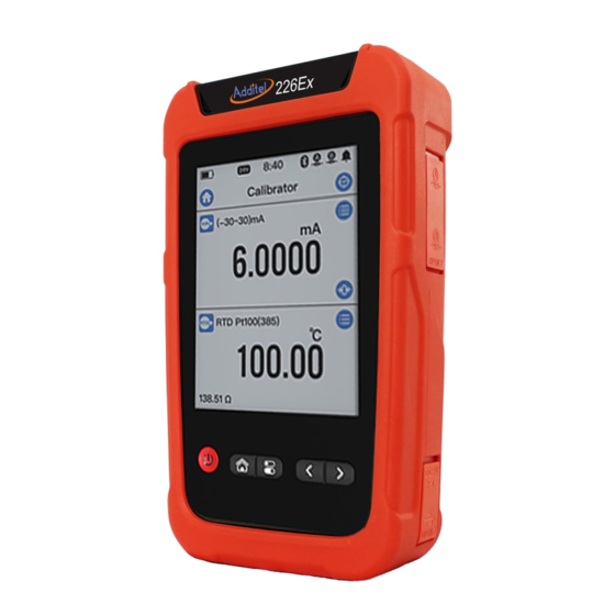
Additel 226Ex User Manual
Documenting multifunction process calibrator
Hide thumbs
1
2
3
Table Of Contents
4
5
6
7
8
9
10
11
12
13
14
15
16
17
18
19
20
21
22
23
24
25
26
27
28
29
30
31
32
33
34
35
36
37
38
39
40
41
42
43
44
45
46
47
48
49
50
51
52
53
54
55
56
57
58
59
60
61
62
63
64
65
66
67
68
69
70
71
72
73
74
75
76
77
78
79
80
81
82
83
84
85
86
87
88
89
90
91
92
93
94
95
96
97
98
99
100
101
102
103
104
105
106
107
108
109
110
111
112
113
114
115
116
117
118
119
120
121
page
of
121
Go
/
121
Contents
Table of Contents
Bookmarks
Table of Contents
Table of Contents
Safety Instructions
Special Safety Requirements
Standard Compliance
Ex Information
Intended Use
Introduction
Product Overview
Technical Specifications
General Specifications
Signal Measure Specifications (Environmental Temp.: 20±10℃, 1 Year Accuracy)
Signal Output Specifications (Environmental Temp.: 20±10°C, 1 Year Accuracy)
Simulate RTD Measure & Output Accuracy (Environmental Temp.: 20±10°C)
Simulate TC Measure & Output Accuracy (Environmental Temp.: 20±10℃)
Figure 1 Basic Structure
Accessories Included
Power Supply Description
Figure 2 Adaptor and the Power Plug
Overview for Display and Functions
Main Interface
Figure 3 Main Interface
Status Bar
Apps List
Main Function Guide
Control Center
Date and Battery
Figure 4 Control Center
Diagnostic Center and Screenshot
Figure 5 Diagnostic Center
Shortcut Settings
Calibrator
Figure 6 Calibrator Main Screen
Electrical Measurement
Voltage Measurement
Figure 7 Voltage/Pulse/Frequency/Switch Measurement
Current Measurement
Frequency Measurement
Figure 8 Current Measurement
Pulse Measurement
Switch Measurement
Filter
Figure 9 Filter Settings
Scaling
Figure 10 Scaling Configurations
Hart
Figure 11 Internal Power+ Internal Resistor
Search and Connection
Settings
Figure 12 External Power + External Resistor
Diagnosis and Service
Figure 13 Current Loop Test
Figure 14 PVAO Zero
Figure 15 D/A Adjustment
Figure 16 Range Migration
Figure 17 Sensor Trim
Process Variable Settings
Figure 18 Process Variable Selection
Temperature Measurement
TC Measurement
Figure 19 TC Measurement
RTD Measurement
Figure 20 RTD Measurement
Pressure Measurement
Output
Voltage Output
Figure 21 Voltage, Frequency, Pulse Output
Current Output
Frequency Output
Pulse Output
Figure 22 Current Output
Simulate TC Output
Figure 23 Simulate TC Output
Simulate RTD Output
Figure 24 Simulate RTD Output
Set Point Output
Automatic Ramp Output
Automatic Step Output
Figure 25 Automatic Step Output Settings
Figure 26 Automatic Step Customize Output Points
Manual Step Output
Figure 27 Automatic Step Customize Output Points
Fine Adjustment Output
System Settings
Bluetooth Communication
Power Management
System Calibration
Services
Maintenance
Restore to Factory
Run Information
System Upgrade
Personalization
Sound
Language
Date & Time
Product Information
Data Management
Task
Calibrating Pressure Devices
Dial Pressure Gauges and Digital Pressure Gauges
Pressure Transmitters
Pressure Switchs
I/P Converter
Figure 28 I/P Converter
Calibrating Temperature Devices
Temperature Indicators
Temperature Transmitters
Figure 29 Temperature Transmitter
Temperature Transmitter with Sensor
Figure 30 Temperature Transmitter with Sensor
Temperature Switchs
Figure 31 Temperature Switch
Temperature Switch with Sensor
Figure 32 Temperature Switch with Sensor
Calibrating Temperature Devices
Delta- Pressure Flowmeters
Instantaneous Flowmeters
Flow Volume Totalizers
Tachometer/ Vortex Meters
Calibrating Loop Devices
Loop Indicators
Loop Signal Source
Signal Isolator/Converters
Limit Switches
Applications
Unit Converter
Leak Test
Leak Testing
PSV Testing
PSV Testing
Thermal Calculation
Sensor Library
Simulating Transmitters
Differential Pressure (DP) Modules
Wiring Help
Advertisement
Quick Links
Download this manual
226Ex/227Ex
Documenting Multifunction Process Calibrator
1
Table of
Contents
Previous
Page
Next
Page
1
2
3
4
5
Advertisement
Table of Contents
Need help?
Do you have a question about the 226Ex and is the answer not in the manual?
Ask a question
Questions and answers
Related Manuals for Additel 226Ex
Test Equipment Additel 226 User Manual
Multifunction process calibrator (108 pages)
Test Equipment Additel 226 User Manual
Multifunction process calibrator (107 pages)
Test Equipment Additel ADT226 User Manual
Multifunction process calibrator (107 pages)
Test Equipment Additel 227Ex User Manual
Documenting multifunction process calibrator (121 pages)
Test Equipment Additel 273E Series Manual
Handheld pressure calibrator (56 pages)
Test Equipment Additel ADT761-D User Manual
Adt761 series automated pressure calibrator (68 pages)
Test Equipment Additel ADT672 User Manual
Digital pressure calibrator (73 pages)
Test Equipment Additel ADT760 User Manual
Automatic handheld pressure calibrator (158 pages)
Test Equipment Additel ADT209 User Manual
Loop calibrator (32 pages)
Test Equipment Additel ADT22 A Series User Manual
Multifunction process calibrators (74 pages)
Test Equipment Additel ADT286 User Manual
Multifunction reference thermometer readout (129 pages)
Test Equipment Additel 761A User Manual
Automated pressure calibrator (151 pages)
Test Equipment Additel ADT 672 User Manual
(73 pages)
Test Equipment Additel 927 Maintenance And Repair Manual
(15 pages)
Test Equipment Additel ADT927 Maintenance Instructions Manual
(8 pages)
Test Equipment Additel 686 User Manual
Advanced digital pressure gauge, advanced digital pressure calibrator (70 pages)
This manual is also suitable for:
227ex
227
226
Table of Contents
Print
Rename the bookmark
Delete bookmark?
Delete from my manuals?
Login
Sign In
OR
Sign in with Facebook
Sign in with Google
Upload manual
Upload from disk
Upload from URL


Need help?
Do you have a question about the 226Ex and is the answer not in the manual?
Questions and answers