Advertisement
Quick Links
Service Instructions
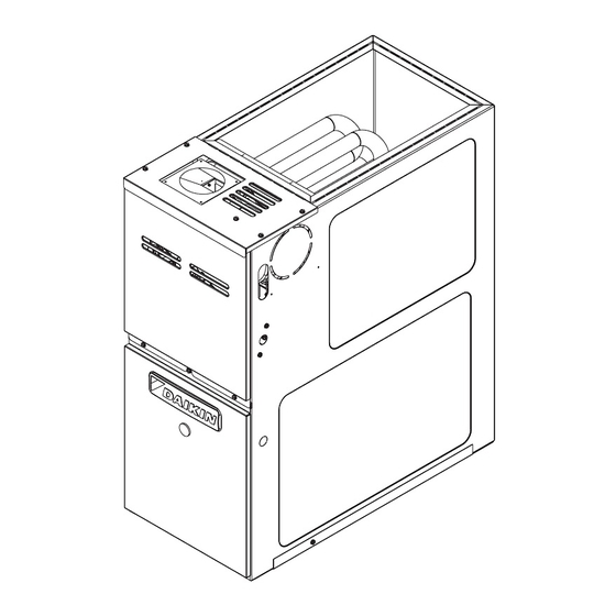
80% Single Stage Ultra-Low NOx Gas Furnaces
DM80SE*U & DM80SN*U
WARNING
ONLY PERSONNEL THAT HAVE BEEN TRAINED TO INSTALL,
ADJUST, SERVICE, MAINTENANCE OR REPAIR (HEREIN-
AFTER, "SERVICE") THE EQUIPMENT SPECIFIED IN THIS
MANUAL SHOULD SERVICE THE EQUIPMENT. THE MANU-
FACTURER WILL NOT BE RESPONSIBLE FOR ANY INJURY
OR PROPERTY DAMAGE ARISING FROM IMPROPER SER-
WARNING
VICE OR SERVICE PROCEDURES. IF YOU SERVICE THIS
UNIT, YOU ASSUME RESPONSIBILITY FOR ANY INJURY OR
DO NOT BYPASS SAFETY DEVICES.
PROPERTY DAMAGE WHICH MAY RESULT. IN ADDITION, IN
JURISDICTIONS THAT REQUIRE ONE OR MORE LICENSES
TO SERVICE THE EQUIPMENT SPECIFIED IN THIS
MANUAL, ONLY LICENSED PERSONNEL SHOULD SERVICE
THE EQUIPMENT.
IMPROPER INSTALLATION, ADJUSTMENT, SERVICING,
MAINTENANCE OR REPAIR OF THE EQUIPMENT SPECIFIED
IN THIS MANUAL, OR ATTEMPTING TO INSTALL, ADJUST,
SERVICE OR REPAIR THE EQUIPMENT SPECIFIED IN THIS
MANUAL WITHOUT PROPER TRAINING MAY RESULT IN
PRODUCT DAMAGE, PROPERTY DAMAGE, PERSONAL
INJURY OR DEATH.
This manual is to be used by qualified, professionally trained HVAC technicians only. Daikin does not assume any
responsibility for property damage or personal injury due to improper service procedures or services performed by an
unqualified
person.The material in this manual does not supercede manufacturer's installation and operation instructions.
RSD6621008r3
Our continuing commitment to quality products may mean a change in specifications without notice.
June 2022
©2019 - 2020, 2022
19001 Kermier Rd. Waller, Tx 77484
www.daikincomfort.com
Advertisement

Related Manuals for Daikin DM80SE U Series


Summary of Contents for Daikin DM80SE U Series
- Page 1 PRODUCT DAMAGE, PROPERTY DAMAGE, PERSONAL INJURY OR DEATH. This manual is to be used by qualified, professionally trained HVAC technicians only. Daikin does not assume any responsibility for property damage or personal injury due to improper service procedures or services performed by an unqualified person.The material in this manual does not supercede manufacturer’s installation and operation instructions.
-
Page 2: Table Of Contents
TABLE OF CONTENTS TROUBLESHOOTING ........15 - 19 IMPORTANT INFORMATION ......2- 4 MAINTENANCE ..........20 - 21 PRODUCT IDENTIFICATION ......5 SERVICING ..........22 - 31 OPERATING INSTRUCTIONS ......6 WIRING DIAGRAMS........32 - 33 SYSTEM OPERATION ........7 - 14 IMPORTANT INFORMATION Pride and workmanship go into every product to provide our customers with quality products. It is possible, however, that during its lifetime a product may require service. -
Page 3: Important Information
IMPORTANT INFORMATION To locate an authorized servicer, please consult your telephone book or the dealer from whom you purchased this prod- uct. For further assistance, please contact: CONSUMER INFORMATION LINE DAIKIN BRAND PRODUCTS TOLL FREE 1-855-770-5678 (U.S. only) email us at: customerservice@daikincomfort.com... - Page 4 IMPORTANT INFORMATION CO can cause serious illness including permanent brain damage or death. B10259-216 Advertencia especial para la instalación de calentadores ó manejadoras de aire en áreas cerradas como estacionamientos ó cuartos de servicio. Las emisiones de monóxido de carbono pueden circular a través del aparato cuando se opera en cualquier modo.
-
Page 5: Product Identification
The model and manufacturing number are used for positive identification of component parts used in manufacturing. Please use these numbers when requesting service or parts information. 7,8,9 Brand Minor Revision D - Daikin Brand B - 1st Revision Configura�on Major Revision B - 1st Revision... -
Page 6: Operating Instructions
OPERATING INSTRUCTIONS... -
Page 7: System Operation
SYSTEM OPERATION Safety IMPORTANT NOTE: The 80% furnace cannot be installed as a direct vent (i.e.., sealed combustion) furnace. Please adhere to the following warnings and cautions when The burner box is present only to help reduce sound installing, adjusting, altering, servicing, or operating the transmission from the burners to the occupied space. - Page 8 SYSTEM OPERATION GAS VALVE HIGH ALTITUDE This unit is equipped with a 24 volt gas valve controlled during furnace operation by the integrated control module. The furnace, as shipped, requires no change to run Taps for measuring the gas supply pressure and manifold between 0-4500 feet.
- Page 9 SYSTEM OPERATION 115 VOLT LINE CONNECTIONS WARNING Before proceeding with electrical connections, ensure that the supply voltage, frequency, and phase correspond to F THE INFORMATION IN THESE INSTRUCTIONS IS NOT FOLLOWED EXACTLY, A that specified on the unit rating plate. Power supply to the FIRE OR EXPLOSION MAY RESULT CAUSING PROPERTY DAMAGE, PERSONAL furnace must be N.E.C.
- Page 10 SYSTEM OPERATION CONTINUOUS FAN OPERATION The single stage furnace control will energize the heating circulator fan speed when the fan switch on the thermostat is turned to the "ON" position. CIRCULATOR BLOWER SPEED ADJUSTMENT WARNING HIGH VOLTAGE LECTRICAL COMPONENTS ARE CONTAINED IN BOTH COMPARTMENTS.
- Page 11 SYSTEM OPERATION display will show the next available item in the main menu. Control Board Status Menu Description of System Status While in the main menu, press the “option” switch to scroll Display through available options corresponding to the main menu item displayed.
- Page 12 SYSTEM OPERATION speed shall stop flashing. Press the menu button again NOTE: If Heat Pump system is configured in OdS to select the option and the control shall immediately menu (HP1 or HP2) COOLING thermostat calls will apply that blower setting and return to the corresponding include “Y1”/Y2”...
- Page 13 SYSTEM OPERATION dimples. Cut out the opening on these lines. An undersized blower. The induced draft blower timing sequence opening will cause reduced airflow. For bottom return is not adjustable. connection, remove the bottom of the cabinet before setting the furnace on the raised platform or return air duct. The integrated control module on all models provides selectable fan on/off delay adjustments.
- Page 14 SYSTEM OPERATION • R and W thermostat contacts close, initiating a call for • Outdoor fan and compressor are de-energized. heat. • Circulator blower is de-energized following a fixed forty • Integrated control module performs safety circuit firve second cool off delay period. Electronic air cleaner checks.
- Page 15 TROUBLESHOOTING DM80SE*U...
- Page 16 TROUBLESHOOTING DM80SE*U...
- Page 17 TROUBLESHOOTING DM80SE*U Fault Code Recall Function: When the SW1 button is pressed momentarily, the control displays the last five (5) fault codes recorded in non- volatile memory upon demand. Operation: Any time the control is powered, the fault code history can be retieved for display by depressing and releasing the SW1 button once (less than 5 seconds);...
-
Page 18: Troubleshooting
TROUBLESHOOTING DM80SN*U Symptom LED Status Fault Description Corrective Actions Stand-by Mode Normal Operation None Normal Operation Furnace fails to operate Internal Control Fault Replace control board Locate and correct gas interruption Furnace lockout due to an excessive number of ignition “retries” (3 Replace or realign igniter total) Check flame sense signal, clean sensor if coated or oxidized... - Page 19 TROUBLESHOOTING DM80SN*U Symptom LED Status Fault Description Corrective Actions Polarity of 115 volt AC is reversed Correct polarity, check and correct wiring if necessary Furnace fails to operate Poor unit ground Verify proper ground, correct if necessary Gas valve is energized when it should not be Check wiring in gas valve circuit Furnace fails to operate ...
-
Page 20: Maintenance
MAINTENANCE Horizontal Unit Filter Removal WARNING Filters in horizontal installations are located in the central return register. HIGH VOLTAGE ISCONNECT POWER BEFORE SERVICING OR INDUCED DRAFT AND CIRCULATION BLOWERS INSTALLING THIS UNIT. ULTIPLE POWER SOURCES MAY The bearings in the induced draft blower and circulator blower BE PRESENT. - Page 21 MAINTENANCE Let's assume the local gas utility has stated that the calorific value of the gas is 1,025 BTU per cubic foot. Multiplying the ninety (90) cubic feet by 1,025 BTU per cubic foot gives us an input of 92,250 BTUH. Checking the BTU input on the rating plate of the furnace being tested.
-
Page 22: Servicing
SERVICING CUBIC FEET GAS RATE -- CUBIC FEET PER HOUR Size of Test Dial Size of Test Dial Seconds for Seconds for cu/ft cu/ft cu/ft cu/ft cu/ft cu/ft cu/ft cu/ft cu/ft cu/ft Revolution Revolution 1800 1636 1500 1385 1286 1200 1125 1059 1000... - Page 23 SERVICING Tubular Heat Exchanger Pressure Sensor Assembly Flue Pipe Connection Gas Valve Inducer Gas Manifold Assembly Grommet Burner Assembly Integrated Control Module Blower Door Interlock Switch Circulator Blower Transformer Tubular Heat Exchanger 11 T ransformer...
- Page 24 SERVICING CHECKING THERMOSTAT, WIRING CHECKING VOLTAGE AND ANTICIPATOR WARNING THERMOSTAT AND WIRING HIGH VOLTAGE ISCONNECT POWER BEFORE SERVICING OR WARNING CHANGING ANY ELECTRICAL WIRING. ULTIPLE POWER SOURCES MAY BE PRESENT. AILURE TO DO SO MAY CAUSE ISCONNECT POWER BEFORE SERVICING. PROPERTY DAMAGE, PERSONAL INJURY OR DEATH.
- Page 25 SERVICING CHECKING DUCT STATIC 1. Remove blower compartment door to gain access to The maximum and minimum allowable external static the thermostat low voltage wires located at the furnace pressures are found in the specification section. These tables integrated control module. also show the amount of air being delivered at a given static 2.
- Page 26 SERVICING rise may result in condensing in or overheating of the heat exchanger. An airflow and temperature rise table is provided in the blower performance specification section. Determine and adjust temperature rise as follows: 1. Operate furnace with burners firing for approximately ten Style 1 minutes.
- Page 27 SERVICING CHECKING AUXILIARY LIMIT CONTROL WARNING O AVOID POSSIBLE FIRE, ONLY RESET THE AUXILIARY LIMIT CONTROL ONCE. F IT SHOULD OPEN A SECOND TIME, A QUALIFIED SERVICER MUST DETERMINE WHY THE AUXILIARY LIMIT OPENED BEFORE RESETTING AGAIN. INDUCED DRAFT BLOWER MOTOR DM80SE*U BLOWER HOUSING WARNING...
- Page 28 SERVICING CHECKING GAS VALVE (Redundant) A combination redundant operator type gas valve which WARNING provides all manual and automatic control functions required for gas fired heating equipment is used. ISCONNECT ELECTRICAL POWER AND SHUT OFF GAS SUPPLY. The valve provides control of main burner gas flow, pressure regulation, and 100 percent safety shut-off.
- Page 29 SERVICING manifold pressure using the table below. WARNING Manifold Gas Pressure HIGH VOLTAGE Natural Gas 2.8 -3.2" w.c. ISCONNECT ELECTRICAL POWER AND SHUT OFF GAS SUPPLY BEFORE SERVICING OR INSTALLING THIS UNIT. The final manifold pressure must not vary from the above ULTIPLE POWER SOURCES MAY BE PRESENT.
- Page 30 SERVICING DM80SE*U WARNING FIELD TEST MODE Function: When the SW1 button is pressed and held until HIGH VOLTAGE the LED is blinking in AMBER (more than 10 seconds, less ISCONNECT ELECTRICAL POWER AND SHUT OFF GAS SUPPLY than 15 seconds), the control will execute a field test mode BEFORE SERVICING OR INSTALLING.
- Page 31 SERVICING DM80SN*U Control Board Main Menu NOTE: The models use PCBF161 with ID Plug. Main Menu Option Menu Description Default 1. Check for 120 volts from Line 1 (Hot) to Line 2 (Neutral) LED Display Display at the ignition control. No voltage, check the door switch Idle - system awaiting i dl connections and wire harness for continuity.
-
Page 32: Wiring Diagrams
WIRING DIAGRAMS DM80SE (with PCBBF161 Control Board) AUTO RESET BURNER TEMPERATURE CONTROL TR (11) INTEGRATED CONTROL MODULE C2 GAS MVC (8) VALVE PRESSURE MVC (8) TRANSDUCER MV(12) PT (3) PT (2) PT (1) MICRO HLI (7) HLO (4) AUTO RESET AUXILIARY LIMIT CONTROLS RO2 (6) - Page 33 DM80SN WIRING DIAGRAMS (with PCBBF241 Control Board) PRESSURE TRANSDUCER 115 VAC/ 1 Ø /60 HZ POWER SUPPLY WITH OVERCURRENT PROTECTION DEVICE ID BLOWER PRESSURE SWITCH DISCONNECT TR (2) GAS VALVE INTEGRATED CONTROL MODULE AUTO RESET PRIMARY LIMIT CONTROL SURFACE IGNITER AUTO RESET 2 CIRCUIT MVC (5)
- Page 34 CUSTOMER FEEDBACK Daikin Comfort Technologies is very interested in all product comments. Please fill out the feedback form on the following link: https://daikincomfort.com/contact-us You can also scan the QR code on the right to be directed to the feedback page.
Need help?
Do you have a question about the DM80SE U Series and is the answer not in the manual?
Questions and answers
Is this product energy efficient
The Daikin DM80SE is 80% efficient, meaning it converts 80% of fuel into heat. While this is standard for a mid-efficiency furnace, it is less energy efficient than high-efficiency models, such as the Carrier 59SC5B080E, which has 96% efficiency.
This answer is automatically generated