
Subscribe to Our Youtube Channel
Related Manuals for Ocean Breeze OBZ-09NPH


Summary of Contents for Ocean Breeze OBZ-09NPH
- Page 1 OBZ-09NPH WWW.OCEANBREEZECOMFORT.COM Read this owner’s manual thoroughly before operating the appliance and keep it handy for reference at all times.
- Page 2 Troubleshooting Tips Read This Manual Inside you’ll find many helpful hints on how to use and maintain your air conditioner properly. Just a little preventive care on your part can save you a great deal of time and money over the life of your air conditioner. You’ll find many answers to common problems in the troubleshooting tips - you should be able to fix most of them quickly before calling service.
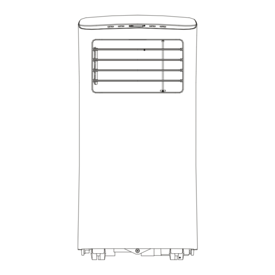
- Page 3 Control panel Handle Horizontal louver (both sides) control lever(adjust manually) Air filter Vertical louver Upper air intake control lever (adjust manually) Drain outlet air outlet Panel Lower air intake Bottom tray Caster drain outlet FRONT REAR Design Notice: In order to ensure the optimal performance of our products, the design specifications of the unit and remote control are subject to change without prior notice.
- Page 4 Please read through these instructions before you start the - DO NOT install your air conditioner in a wet room such as installation process. Improper installation can cause a bathroom or laundry room. Too much exposure to water damage to the unit, your personal property, and also poses can cause electrical components to short circuit.
- Page 5 WARNING: (for using R290/R32 refrigerant only) - Do not use means to accelerate the defrosting process or to clean, other than those recommended by the manufacturer. - The appliance shall be stored in a room without continuously operating ignition sources (for example: open flames, an operating gas appliance) and ignition sources (for example: an operating electric heater) close to the appliance.
- Page 6 - Please follow the instruction carefully to handle, install, clear, service the air conditioner to avoid any damage or hazard. Flammable Refrigerant R32 is used within air conditioner. When maintaining or disposing the air conditioner, the refrigerant (R32 or R290) shall be recovered properly, shall not discharge to air directly.
- Page 7 1. Transport of equipment containing flammable refrigerants See transport regulations 2. Marking of equipment using signs See local regulations 3. Disposal of equipment using flammable refrigerants See national regulations. 4. Storage of equipment/appliances The storage of equipment should be in accordance with the manufacturer's instructions. 5.
- Page 8 3) General work area All maintenance staff and others working in the local area shall be instructed on the nature of work being carried out. Work in confined spaces shall be avoided. The area around the workspace shall be sectioned off. Ensure that the conditions within the area have been made safe by control of flammable material.
- Page 9 that there are no flammable hazards or ignition risks. No Smoking signs shall be displayed. 7) Ventilated area Ensure that the area is in the open or that it is adequately ventilated before breaking into the system or conducting any hot work. A degree of ventilation shall continue during the period that the work is carried out.
- Page 10 9) Checks to electrical devices Repair and maintenance to electrical components shall include initial safety checks and component inspection procedures. If a fault exists that could compromise safety, then no electrical supply shall be connected to the circuit until it is satisfactorily dealt with. If the fault cannot be corrected immediately but it is necessary to continue operation, an adequate temporary solution shall be used.
- Page 11 NOTE: The use of silicon sealant may inhibit the effectiveness of some types of leak detection equipment. Intrinsically safe components do not have to be isolated prior to working on them. 8. Repair to intrinsically safe components Do not apply any permanent inductive or capacitance loads to the circuit without ensuring that this will not exceed the permissible voltage and current permitted for the equipment in use.
- Page 12 and shall be calibrated to the refrigerant employed and the appropriate percentage of gas (25 % maximum) is confirmed. Leak detection fluids are suitable for use with most refrigerants but the use of detergents containing chlorine shall be avoided as the chlorine may react with the refrigerant and corrode the copper pipe-work.
- Page 13 place. Ensure that the outlet for the vacuum pump is not close to any ignition sources and there is ventilation available. 13.Charging procedures In addition to conventional charging procedures, the following requirements shall be followed. Ensure that contamination of different refrigerants does not occur when using charging equipment. Hoses or lines shall be as short as possible to minimise the amount of refrigerant contained in them.
- Page 14 cylinders conform to the appropriate standards. d) Pump down refrigerant system, if possible. e) If a vacuum is not possible, make a manifold so that refrigerant can be removed from various parts of the system. f) Make sure that cylinder is situated on the scales before recovery takes place. g) Start the recovery machine and operate in accordance with manufacturer's instructions.
- Page 15 In addition, a set of calibrated weighing scales shall be available and in good working order. Hoses shall be complete with leak-free disconnect couplings and in good condition. Before using the recovery machine, check that it is in satisfactory working order, has been properly maintained and that any associated electrical components are sealed to prevent ignition in the event of a refrigerant release.
- Page 16 - This appliance is not intended for use by persons (including children) with reduced physical, sensory or mental capabilities or lack of experience and knowledge, unless they have been given supervision or instruction concerning the use of the appliance by a person responsible for their safety. - Children should be supervised to ensure that they do not play with the appliance.
- Page 17 Your installation location should meet the following requirements: - Make sure that you install your unit on an even surface to minimize noise and vibration. - The unit must be installed near a grounded outlet, and the Collection Tray Drain (found on the back of the unit) must be accessible. - The unit should be located at least 19.7 inches from the nearest wall to ensure proper air conditioning.
- Page 18 Suggested Tools Step One: Preparing the exhaust hose assembly. - Medium Phillips screwdriver; - Tape measure or ruler; Press the exhaust hose into the window slider adaptor and the unit adaptor. Each adaptor will snap into the exhaust hose automatically with - Knife or scissors;...
- Page 19 Foam seal B (Short adhesive foam seal for right and left sides) Window slider B (if required) Window slider A Foam seal A (Long adhesive foam seal for top and bottom sides) Insert the window slider assembly on the bottom sash channel. Use care when installing the window Foam seal B (Short adhesive slider assembly, which will now...
- Page 20 Note: This air conditioner exhausts hot air from the back of the unit • While operating in cool mode, the exhaust hose will become warm to the touch (this is normal). • Having the exhaust hose overextended can cause radiant heat into the room causing ineffective operation.
- Page 21 MODE button Selects the desired operating mode. Each time you press the button, a mode is selected in a sequence that goes from COOL, FAN, and DRY. The mode light illuminates and indicates the selected mode. Up (+) and Down (-) buttons Used to adjust (increasing/decreasing) temperature settings in 1°C/1°F increments in a range of 17°C/62°F to 30°C/86°F.
- Page 22 - In cool mode, this unit is made to self-evaporate. This means if you keep the rubber stoppers closed on the back of the unit, the water will evaporate and you will not have to drain. - In cases of extreme humidity, you may have some water accumulation that the unit is unable to evaporate.
-
Page 23: Water Drainage
SLEEP/ECO operation WATER DRAINAGE - This feature can be activated from the remote control ONLY. Activating SLEEP - During dehumidifying modes, remove the drain plug feature will increase the selected temperature by 1°C/1°F after 30 minutes. The Remove the from the back of the unit, install the drain connector drain plug temperature will again increase (cooling) by another 1°C/1°F after an additional 30 (5/8"... - Page 24 down the grille Gently wash the air filter using water and/or diluted liquid dishwashing detergent. Rinse thoroughly and gently shake excess water from the filters. Make sure the filters are dry before reinstalling. NOTE: You may use a vacuum cleaner to remove dust. Air filter (take out) Be sure to store the unit in a cool, dark place.
-
Page 25: Troubleshooting Tips
Troubleshooting Tips Before calling for service, review this list. It may save you time and expense. This list includes common problems that may not be the result of defective workmanship or materials in this appliance. - Page 26 Troubleshooting Tips 1. The P1 code indicates that there is moisture in the machine and the unit has to be dried out in order to operate correctly. 2. Please drain all the water out of the bottom drain plug. The drain tray is located in the bottom of the unit behind the bottom drain plug and cannot be removed.
Need help?
Do you have a question about the OBZ-09NPH and is the answer not in the manual?
Questions and answers
remote wont change from cel
what are the BTU'S on an OBZ-09NPH