Advertisement
Quick Links
M9310 Series Electric Non-Spring Return Actuators
Installation Guide
M9310-HGA-3
Applications
IMPORTANT: Use this M9310 Series Electric
Non-Spring Return Actuator only to control
equipment under normal operating conditions.
Where failure or malfunction of the electric actuator
could lead to personal injury or property damage to
the controlled equipment or other property,
additional precautions must be designed into the
control system. Incorporate and maintain other
devices, such as supervisory or alarm systems or
safety or limit controls, intended to warn of or protect
against failure or malfunction of the electric actuator.
Installation
Parts included
•
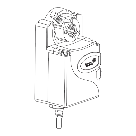
M9310 Series actuator
Figure 1:
M9310 Series Electric Non-Spring Return Actuators Installation Guide
M9310 actuator
Part No. 34-636-2456, Rev. D
•
anti-rotation bracket
Figure 2:
Anti-rotation bracket
•
M3.5 x 9.5 mm long self-tapping crossed recessed
screw
Figure 3:
Special tools needed
•
torque wrench with 12 point 3/8 in. or 5/16 in.
open-end wrench
•
5/16 in. screwdriver
•
digital voltmeter
Accessories
Table 1: Accessories (order separately)
Code number
Description
M9000-321
Weathershield kit
M9300-1
Auxiliary switch kit (single-pole,
double-throw)
M9300-2
Auxiliary switch kit (two single-pole,
double-throw)
M9300-100
Threaded conduit adapters for
1/2 in. electrician's fittings
M9300-140
Feedback potentiometer 140k
ohms
M9300-151
Remote mounting kit, with crank
arm and damper linkage
M9300-1K
Feedback potentiometer 1k ohms
M9300-2K
Feedback potentiometer 2k ohms
M9300-10K
Feedback potentiometer 10k ohms
1
Issued December 2022
Self-tapping screw
Advertisement

Subscribe to Our Youtube Channel
Related Manuals for Johnson Controls M9310-HGA-3


Summary of Contents for Johnson Controls M9310-HGA-3
- Page 1 M9310 Series Electric Non-Spring Return Actuators Installation Guide M9310-HGA-3 Part No. 34-636-2456, Rev. D Issued December 2022 Applications • anti-rotation bracket IMPORTANT: Use this M9310 Series Electric Non-Spring Return Actuator only to control equipment under normal operating conditions. Where failure or malfunction of the electric actuator...
- Page 2 Mounting Figure 7: Rotating coupler Figure 4: Mounting positions IMPORTANT: The M9310 Series actuator is not rated for outdoor use. Do not mount the M9310 outdoors without the M9000-321 weathershield kit, or it may fail to operate. Adjusting the angular rotation stops Figure 8: Installing coupler Figure 5:...
- Page 3 2. Bend or cut the anti-rotation bracket to fit the damper frame or duct. Table 2: Shaft diameter and required torque Shaft With insert Without Anti-Rotation diameter, in. insert Bracket Tab Slot for Bracket (mm) M3.5 Screws (2) Anti-Rotation Bracket 3/4 (19) (9.5) (12.7)
- Page 4 6. Swing the anti-rotation bracket under the actuator b. Rotate the coupler fully closed to fully open to until it reaches the middle of the slot on the bottom verify that the damper and actuator rotate of the actuator. freely throughout the range. Figure 13: Securing the anti-rotation bracket to the damper frame 7.
- Page 5 IMPORTANT: When using the M9310-HGA-3 actuator in floating mode, verify that the DIP switch is positioned on the 2 to 10 VDC option. This setting ensures compatibility with the controller’s triac...
-
Page 6: Operation
Operation Auto calibration mode The actuator enters auto calibration mode and positions the coupler to the maximum and minimum end stops to identify the range of travel. Risk of Property Damage. Accessing the dip switches and LEDs Do not apply power to the system before checking all Locate the oval cover on the front of the unit and pull wiring connections. - Page 7 4. Press INC. Table 3: DIp switch settings The Offset Adj. LED flashes. The voltage reading on the multimeter increases 0.5 VDC each time Example Command Feedback Settings M9310-HGA you press the button. Press INC. until you reach signal signal user interface the desired voltage.
-
Page 8: Repair Information
Repair information If the M9310 Series Electric Non-Spring Return Actuators fail to operate within its specifications, replace the unit. For a replacement actuator, contact the nearest Johnson Controls® representative. Figure 22: Repositioning the actuator hub Callout Description Manual override button... -
Page 9: Technical Specifications
The performance specifications are nominal and conform to acceptable industry standard. For application at conditions beyond these specifica- tions, consult the local Johnson Controls office. Johnson Controls shall not be liable for damages resulting from misapplication or misuse of its products. - Page 10 Johnson Controls. All other marks herein are the marks of their respective owners. © Copyright 2022 Johnson Controls. All rights reserved. Any unauthorized use or copying is strictly prohibited. M9310 Series Electric Non-Spring Return Actuators Installation Guide...
Need help?
Do you have a question about the M9310-HGA-3 and is the answer not in the manual?
Questions and answers