
Related Manuals for YAMADA DP-15 Series


Summary of Contents for YAMADA DP-15 Series
- Page 1 Doc. No. NDP 456U-05 OPERATION MANUAL YAMADA AIR-OPERATED DOUBLE DIAPHRAGM PUMP DP-15 series...
-
Page 2: For Safe Operation
·Introduction Thank you for purchasing a Yamada Diaphragm Pump. This product is a positive-displacement pump that transfers fluids by movement of diaphragms driven by compressed air through a unique switching mechanism. The casing that comes in contact with the fluid is made of aluminum, stainless steel, forged iron, polypropylene, Polyacetal, polyvinylidene fluoride depending on the model you have selected according to the type of fluid to be pumped. -
Page 3: Warnings And Cautions
·Warnings and cautions For safe use of this product, be sure to note the following: In this document, warnings and cautions are indicated by symbols. These symbols are for those who will operate this product and for those who will be nearby, for safe operation and for prevention of personal injury and property damage. - Page 4 (because of freezing or heat), which may cause damage to the pump and/or piping, and possible leakage of fluid. · Always use genuine Yamada parts when replacing component parts of this product. Do NOT attempt to modify the components parts or replace them with other than genuine Yamada parts.
- Page 5 WARNING · When pumping a hazardous fluid (hot, flammable, strong acid, etc.) with this product, provide protective measures (install a pit, a protection box, sensors, etc.) in consideration of possible leakage of fluid, and post warning signs at necessary places. Make the warning symbols in “12.Warning symbols”, and attach them to the casing and piping, etc.
-
Page 6: Table Of Contents
·Operating caution ···································································· 2 ·Table of contents ······································································ 5 1. Names of parts and materials 1.1 DP-15 series ········································································ 6 2. Assembly 2.1 Installation of accessories ······················································ 7 3. Installation 3.1 Method of transport ······························································ 8 3.2 Installing the pump ······························································ 8 3.3 Connecting the ground wire ··················································... -
Page 7: Names Of Parts And Materials
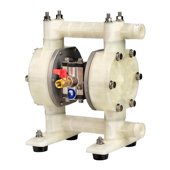
1. Names of parts and materials 1.1 DP-15 series A: Air valve F: Pump Base B: Reset Button G: Discharge Port C: Out Manifold H: Intake port D: Out Chamber I : Lift Point E: In Manifold J : Ground Connection point □... -
Page 8: Assembly
2. Assembly 2.1 Installation of accessories 1) First, open the product package and make sure that all the accessories are in order (see “1. Names ■ of parts and materials” List of accessories). 2) Attach the air valve and the silencer (see the appearance drawings on “1. Names of parts and materials”). -
Page 9: Installation
3. Installation 3.1 Method of transport · When lifting the pump using a chain hoist or crane before transporting it, be sure to lift it by the specified lift point (see “1. Names of parts and materials”). WARNING · Be careful that nobody will pass under the pump when you lift it. It would be very dangerous if the pump should fall. - Page 10 CAUTION · Even if you do not use the cushions to secure the pump in place, mount it in such a way that vibration generated by pump operation will be absorbed. · If the pump will be submerged during operation, follow the steps below: *Verify the corrosion resistance of each component of the pump, and do NOT expose the pump to any fluid for which it does not have proper corrosion resistance.
-
Page 11: Connecting The Ground Wire
3.3 Connecting the ground wire When installing the pump, be sure to connect the ground wire at the specified position. For the specified position for connecting the ground Position for wire, see “1. Names of parts and materials”. connecting the b) Also connect ground wires to peripheral ground wire equipment and piping. -
Page 12: Connection
4. Connection 4.1 Connecting fluid piping 1) Connect a flow valve and a drain valve to the fluid discharge port of the pump. 2) Connect a valve for maintenance to the fluid suction intake port of the pump. 3) Connect a hose to the valve on the suction-port side and the valve of the discharge-port side of the pump. -
Page 13: Connecting Air Piping
4.2 Connecting air piping WARNING · Before starting work, make sure that the air compressor is shut off. Connect an air valve, air filter, regulator and if necessary lubricator (hereinafter called the "peripheral equipment") to hose which connected to compressor. Install air valve on the air inlet of the pump. -
Page 14: Operation
5. Operation 5.1 Method of operation CAUTION · Before starting the pump, make sure that all piping is properly connected. · Also, before starting the pump, make sure that all the bolts are securely tightened. (Refer to the maintenance manual for the bolts that a regulation torque are explained.) ·... -
Page 15: Shutdown
5.3 Shutdown · Close the air valve of the pump and shut off the supply air. CAUTION · There is no problem in shutting down the pump with the flow valve closed while air is being supplied; however, if this condition continues for many hours while there is nobody watching the pump, it may continue running when there is a leak from the pump or piping, and fluid may continue flowing out of the position of leakage. -
Page 16: Method Of Cleaning
6. Method of cleaning WARNING · Before starting operation, make sure that compressed air is not supplied to the pump. · Before starting operation, make sure that the pump is not pressurized. 1) Remove the hose from the suction side of the pump. 2) Close the flow valve on the discharge side, open the drain valve, and then operate a pump by starting air pressure for a while to discharge any fluid remaining inside the pump as much as possible. -
Page 17: Daily Check
7. Daily check · Before starting pump operation, be sure to conduct the following check every day. If any irregularity is found, do NOT start running the pump until the cause of the irregularity has been found and corrective measures have been taken. a) Verify the drain flow through the air filter. -
Page 18: Fluid Leaks From Exhaust Port (Silencer)
8.4 Fluid leaks from exhaust port (silencer) Cause Action to be taken The diaphragm is damaged. Disassemble and check the pump and replace the diaphragm. The fastening nuts for the center disk are loose. Disassemble and check the pump. Tighten the nuts. 8.5 High air consumption during in operation Cause Action to be taken... -
Page 19: Main Body Specifications
*1. Maximum air pressure for non-metallic pumps decreases with temperature (See 18 page Temperature Pressure Curve). *2. Discharge Volume/cycle is highly dependent on application. Contact your local distributor or Yamada for more information. *3. Do not use the flat valve type pump for the liquids with slurry. -
Page 20: Appearance And Dimensions
10.2 Appearance and dimensions ■DP-15FP□/ BP□/ FVT [ ]:FVT 139.5[138] LIQUID OUTLET Rc1/2 AIR INLET Rc1/4 EXHAUST LIQUID INLET Rc3/8 Rc1/2 149[146] 4-Φ9 246[244] CAUTION · Due to improvement or modification of products, dimensions may change without notice. Please contact your distributor our regional office for detailed information. -
Page 21: Performance Curve
10.3 Performance curve ■DP-15FP□/ BP□/ FVT NOTE: Method of measurement of performance curve Measuring instruments and procedure Fig.10.1 ▪ Conditions a) Supplied air pressure: Maintaining preset pressure b) Liquid pumped: Fresh water c) Temperature: Ambient d) Condition of suction: Flat suction 0 feet head e) Measuring system: System A ……... -
Page 22: Limited Warranty
11. Limited warranty If an abnormality occurs during normal operation in accordance with the operating instructions and other operating cautions within the warranty period (12 months after date of purchase) that can be attributed to a manufacturing defect, the defective parts of this product will be serviced or the product will be replaced free of charge. -
Page 23: Warning Symbols
12. Warning symbols BEWARE: HIGH ELECTRIC SHOCK POISON TEMPERATURE FLAMMABLE CORROSION EXPLOSION General warnings, cautions and FIRE STRICTLY PROHIBITED danger notifications... - Page 25 YAMADA EUROPE B.V . Aquamarijnstraat 50,7554 NS Hengelo (O),The Netherlands PHONE : +31-(0)74-242-2032 : +31-(0)74-242-1055 E-mail : sales@yamada.nl : www.yamada-europe.com Manufactured by YAMADA CORPORATION INTERNATIONAL DEPARTMENT 1-1-3, Minami-Magome,Ota ku, Tokyo, 143-8504, Japan PHONE : +81-(0)3-3777-0241 : +81-(0)3-3777-0584 E-mail : intl@yamadacorp.co.jp : www.yamadacorp.co.jp...
Need help?
Do you have a question about the DP-15 Series and is the answer not in the manual?
Questions and answers