
Related Manuals for YAMADA DP-20F/P


Summary of Contents for YAMADA DP-20F/P
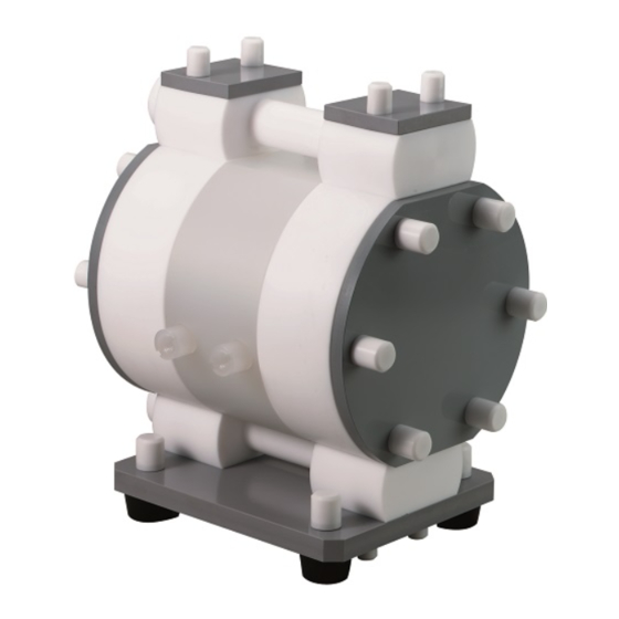
- Page 1 Doc. No. NDP403M-05 MAINTENANCE MANUAL YAMADA AIR-OPERATED DOUBLE DIAPHRAGM PUMP DP-20F/P DP-25F/P DP-25F/C DP-38F/P DP-38F/C...
-
Page 2: Warnings And Cautions
After reading the manual, keep it in an easy-to-access place so that the user may refer to it whenever necessary. This maintenance manual describes the items required for maintenance of the Yamada DP-F/P, DP-F/C series Diaphragm Pumps. This document is based on the products that are manufactured in March 2011. NOTE that its contents are subject to change as a result of specification changes to be made in future. -
Page 3: Table Of Contents
Table of Contents ·Warnings and Cautions ·Table of Contents 1.Principles of operation --------------------------------------------------------------- 1 2.Tools, etc. 2.1 General tools ---------------------------------------------------------------------- 1 2.2 Special tools ----------------------------------------------------------------------- 1 2.3 Others ------------------------------------------------------------------------------- 1 .Balls, Flat valves and Valve seats 3.1 Removal ---------------------------------------------------------------------------- 2 3.2 Inspection ■... -
Page 4: Principles Of Operation
1. Principles of operation There are two diaphragms fixed to the center rod, one at each end. When compressed air is supplied to air chamber b (right side, see Fig.1.1), the center rod moves to the right, the material in material chamber B is pushed out, and at the same time material is sucked into material chamber A. -
Page 5: Balls, Flat Valves And Valve Seats
3. Balls, Flat valves and Valve seats 3.1 Removal ▪ Remove the 8 caps (4 on the top and 4 on the bottom) from both sides of the vertical tie rods. [Fig.3.1] Fig.3.1 ▪ Unscrew the 4 retainer nuts from the upper side of the vertical tie rods. -
Page 6: Inspection Ball Valve Types
▪ Replace the PTFE O rings regardless of its condition. Fig.3.10 ▪ Make sure that the directions of each coned disk spring DP-20F/P, DP-25F/P are correct. [Fig.3.10, Fig.3.11] ▪ Retighten the tie rods before starting the pump. (See [7. Retightening of tie rods]) -
Page 7: Diaphragm And Center Rod
4. Diaphragm and Center rod 4.1 Removal ▪ Remove the balls or flat valves, valve seats, valve guides, valve stoppers, etc. (see [3.1 Removal]) ▪ Remove the 12 caps (16 caps for DP-38F/□) from both sides of horizontal tie rods. [Fig.4.1] Fig.4.1 ▪... -
Page 8: Inspection
Measure the diameter, and if it is not within the Fig.4.7 permissible range, replace the center rod. Permissible range of center rod diameter DP-20F/P Ø 17.92 - Ø 17.98 mm DP-25F/P, DP-25F/C Ø 23.92 - Ø 23.98 mm DP-38F/P, DP-38F/C Ø... -
Page 9: Pilot Valve Assembly, Valve Seats
DP-20F/P, DP-25F/P Fig.4.10 <NOTE> ▪ Make sure the sealing surface is not dirty or damaged. ▪ Tighten the nuts evenly and alternately in a diagonal sequence to the specified torque. ▪ Make sure that the directions of each coned disk spring are correct. -
Page 10: Installation
5.3 Installation For installation, see [Exploded View] on the separate sheet and install in the reverse order of disassembly. <NOTE> ▪ The O ring on the valve seat is easily separated. Ensure that the O ring is fitted on the valve seat when attaching the valve seat to the body. - Page 11 ▪ Use pliers to pull out the C spool valve assembly. [Fig.6.4] Fig.6.4 ▪ Remove the sleeve from the valve body using the sleeve remover (special tool: Part No. 713148). [Fig.6.5] <NOTE> ▪ Be careful not to damage or crack the sliding surface when pulling out the C spool valve assembly and sleeve.
-
Page 12: Inspection
Replace the O ring if it is worn out or cracked. <NOTE> ▪ Be sure to replace the spool and sleeve together as a complete set. (Set No : DP-20F/P 804395 DP-25,38F/P 804396 DP-25,38F/C 804170) ▪ C spring [Fig.6.12] Measure the dimension shown on the left figure, and if it is not within the permissible range, replace the C spring. -
Page 13: Installation
6.3 Installation For installation, see [Exploded View] on the separate sheet and install in the reverse order of disassembly. Tightening torque for Valve body installation bolts DP-20F/P 2 N•m DP-25F/P, DP-25F/C 7 N•m DP-38F/P, DP-38F/C <NOTE> ▪ Make sure the sealing surface is not dirty or damaged. -
Page 14: Instructions For Applying Lubrication
8. Instructions for applying lubrication 8.1 Applying Lubricant to the Packing ▪ Apply plenty of grease to a v-groove of the packing. <NOTE> ▪ Be careful not to produce air bubbles when applying grease. Fig.8.1 8.2 Applying Lubricant to the Center Rod ▪... - Page 16 Manufactured by YAMADA CORPORATION INTERNATIONAL DEPARTMENT No.1-3, 1-Chome, Minami- Magome, Ohta-Ku, Tokyo, 143-8504, Japan PHONE : +81-(0)3-3777-0241 : +81-(0)3-3777-0584 201704 NDP403M...
Need help?
Do you have a question about the DP-20F/P and is the answer not in the manual?
Questions and answers