
Related Manuals for YAMADA DP-10F


Summary of Contents for YAMADA DP-10F
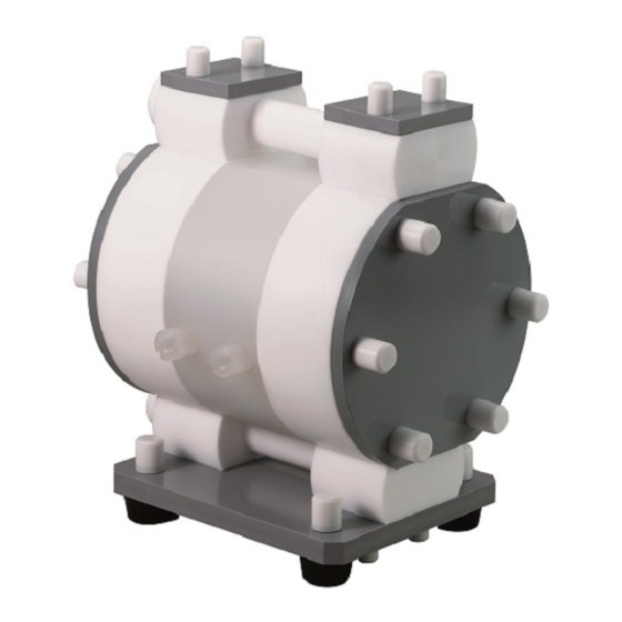
- Page 1 Doc. No. NDP 149M-06 MAINTENANCE MANUAL YAMADA AIR-OPERATED DIAPHRAGM PUMPS DP-10Fi DP-20Fi...
-
Page 2: Warnings And Cautions
After reading the manual, keep it in an easy-to-access place so that the user may refer to it whenever necessary. This maintenance manual describes the items required for maintenance of the Yamada DP-Fi series Diaphragm Pumps. This document is based on the products that are manufactured in March 2011. Note that its contents are subject to change as a result of specification changes to be made in future. -
Page 3: Table Of Contents
Table of Contents · Warnings and Cautions · Table of Contents 1. Principles of operation ·························································· 1 2. Tool and Others Required 2.1 General tools ······································································ 1 2.2 Dedicated tools ··································································· 1 2.3 Others. ·············································································· 2 3. Ordering Replacement parts ·················································... -
Page 4: Principles Of Operation
1. Principles of operation Liquid material chambers are located inside and air chambers are located outside of the DP-Fi series pump.When compressed air is supplied to the air chamber “a” (see the left figure below) by the switch valve of this pump, the center rod starts moving to the left to cause liquid in the liquid material chamber “A”... -
Page 5: Others
④ Sleeve remover (optional) ⑤ Cap remover (optional) Purpose: Removing sleeves, valve seat and Purpose: Removing a cap. funnel. (Part No. 771132) (Part No. 713148) ⑥ Ring Wrench ⑦ Support Ring Wrench □ □ DP-10Fi/ /H (Part No. 832802) DP-10Fi/ /H (Part No. -
Page 6: Base
4. Base □ 4.1 Removal(only Fi/ /R) Follow the steps below to separate the pump main unit from the base. ・ Remove the fixing screw (one). [Fig.4-1] ・ Slide the pump main unit toward the fixing screw, then raise and remove it from the base. [Fig.4-2] 4.2 Installation For installation, see [Exploded View] on the separate sheet and install in the reverse order of disassembly. -
Page 7: Valve Body And C Spool Valve Assembly
5. Valve Body and C Spool Valve Assembly 5.1 Removal ■ □ Valve body assembly /R) ( ・ Remove the cap from each hexagon-headed bolt (part “a”). [Fig.5-1] ・ Remove the hexagon-headed bolts (four). ・ Put the bolt (M8 × 1.25 × 30 or larger) on the tip of the pin (part “b”), and screw it. - Page 8 ■ □ Valve body assembly /H) ( ・Remove air tube from fitting.〔Fig.5-6〕 ・ Screw in bolt (M8×1.25×30) and pull up pin then remove pin. ・Remove valve body from pump body. Fig.5-6 ・Remove air tube from fitting〔Fig.5-7〕 Fig.5-7 ・Use the dedicated tool ⑤(Cap remover) to remove cap from valve body assembly.〔Fig.5-8〕...
-
Page 9: Disassembling Of The C Spool Valve
■ Disassembling of the C Spool Valve ・ Use a flat-blade screwdriver to raise the outside of the C spring so that the outside can be opened, and remove the C spring. [Fig.5-11 and 5-12] <NOTE> - When you remove the C spring, the arm is removed also. -
Page 10: Inspection
5.2 Inspection ・ Spool Measure the outside diameter, and if it is out of the allowable range, replace the spool with a new one. [Fig.5-15] Allowable range of the spool □ DP-10Fi/P/ φ15.73 ~ φ15.80 mm □ Fig.5-15 DP-20Fi/P/ □ DP-10Fi/C/ φ15.77 ~... -
Page 11: Installation
5.3 Installation For installation, see [Exploded View] on the separate sheet and install in the reverse order of disassembly. Tightening torque of the hexagon-headed bolt of the piping block □ DP-10Fi/ 4 N・m □ DP-20Fi/ <NOTE> - Make sure there is no dust on the seal surface and the seal is not damaged. -
Page 12: Ball Valves And Valve Seats
6. Ball Valves and Valve Seats □ 6.1 Removal(Figure displays Fi/ /R) ・ Use the dedicated tool (valve cap remover) to remove the valve cap and valve stopper. [Fig.6-1 and 6-2] (Dedicated tool ① for DP-10Fi or dedicated tool②for DP-20Fi) ・... -
Page 13: Inspection
6.2 Inspection ■ Ball valve ・ Ball [Fig.6-5] Measure the outside diameter, and if it is out of the allowable range, replace the ball with a new one. Allowable range of the ball DP-10Fi Sφ14.3 ~ Sφ16.3 mm DP-20Fi Sφ24.3 ~ Sφ27.8 mm ・... -
Page 14: Diaphragm And Center Rod
7. Diaphragm and Center Rod □ 7.1 Removal Fi/ ・ Remove the base,valve body assembly and piping block in the way instructed in Section “4.1 Removal” of “4. Base” and “valve body assembly” of “5.1 Removal.” [Fig.7-1] ・ Remove the 12 caps from the both sides of horizontal tie rods. - Page 15 □ Disassemble Fi / ・ Refer to instructions for disassembling of the valve body assembly. 〔Fig.7-7〕 Fig.7-7 ・ Use the dedicated tool ⑦(Support Ring Wrench) to loosen support ring.( turn180 degree Approx) 〔Fig.7-8〕 ・ Use the dedicated tool ⑥(Retaining Ring Wrench) to remove retaining ring.
-
Page 16: Inspection
7.2 Inspection ・ Diaphragm If the diaphragm is worn out or damaged, replace it with a new one. Guideline of diaphragm life (when used with clean water at room temperature) DP-10Fi 12,000,000 cycle DP-20Fi 6,000,000 cycle ・ Center rod [Fig.7-13] Measure the diameter, and if it is out of the allowable Fig.7-13 range, replace the center rod with a new one. - Page 17 For installation, see [Exploded View] on the separate sheet and install in the reverse order of disassembly. Tightening Torque values DP-10 Fi/□/H 40 N・m DP-20 Fi/□/H 60 N・m Fig.7-17 <NOTE> After fitting the retaining ring, point (A) must be in the down position.
-
Page 18: Pilot Valve Assembly
8. Pilot Valve Assembly □ 8.1 Removal(Figure displays Fi/ /R) ・ Use the dedicated tool ③(guide holder remover) to remove the spring seat. [Fig.8-1] ・ Remove the spring and the pilot valve assembly. [Fig.8-2] ・Remove the valve sheet by using dedicated tool ⑤(cap remover) [Fig.8-3]... -
Page 19: Retightening Of Tie Rods
□ 9. Retightening of Tie rods(only Fi/ /R) ・ Since the dimensions of this pump may vary according to the temperature or with the passage of time due to the characteristics of its material: resin. Therefore, check to see if any liquid material leaks at each sealed portion periodically, and retighten the parts indicated with arrow marks. - Page 20 Manufactured by YAMADA CORPORATION INTERNATIONAL DEPARTMENT No.1-3, 1-Chome, Minami- Magome, Ohta-Ku, Tokyo, 143-8504, Japan PHONE : +81-(0)3-3777-0241 : +81-(0)3-3777-0584 201612 NDP149M...
Need help?
Do you have a question about the DP-10F and is the answer not in the manual?
Questions and answers