Table of Contents
Advertisement
Quick Links
Advertisement
Table of Contents

Related Manuals for STL STRIKER 2


Summary of Contents for STL STRIKER 2
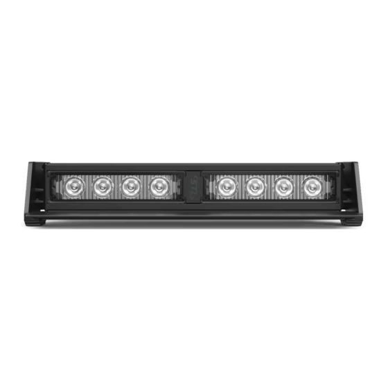
- Page 1 STRIKER ® DASH LIGHT B-STT2 INSTRUCTION MANUAL SpeedTech Lights, Inc © 2019...
- Page 2 This document must be delivered to and read by the end user and installer as it serves to provide you with the required information for proper and safe use of your STL product. Before operating this or any STL products the user and installer must read this manual all the way through. You will find important information in this manual that could prevent property damage and/or serious injury to the user and installer.
- Page 3 Grommets, cable ties, looms, and other installation hardware should be used to anchor and protect all wiring. Fuses should be properly sized and located as close to the power take off points as possible to protect the wiring and device. To protect against short circuits, a fuse is included by STL for all products.
- Page 4 STRIKER ® DASH LIGHT Wiring Diagram Wire Color Function Positive- Memory Mode 1 Red* Negative Black* Flash Pattern Yellow Positive- Memory Mode 2 Green Sync (Max 2 units) White * Indicates a main power cable. NOTE: All cables except Negative contact +12 VDC. Specifications Voltage 12 VDC...
- Page 5 STRIKER ® DASH LIGHT 90° Suction Cup Bracket (Sold Separately) • Position the slide track screws included with the unit such that the screws line up with the bracket oval tracks. Use the included nuts and washers to secure the bracket to the unit. •...
- Page 6 STRIKER ® DASH LIGHT Windshield Visor Assembly and Mounting The windshield visor contents include: • (1) Visor • (2) Visor end caps • (6) Short screws • (4) Long screws 1. Remove the stock end cap screws from both ends of the Light Bar. NOTE: Save these screws to revert back to non-visor configuration.
- Page 7 NOTE: It’s best to connect both units to a single control switch when syncing units together. About Flash Patterns • All STL LED products are equipped with a non-volatile memory which will recall the last flash pattern when the product is turned on. • Follow the wiring diagram to identify the Flash Pattern wire to manually cycle through patterns.
Need help?
Do you have a question about the STRIKER 2 and is the answer not in the manual?
Questions and answers