Table of Contents
Advertisement
Quick Links
Advertisement
Table of Contents

Related Manuals for Apogee Instruments APOGEE LINE QUANTUM


Summary of Contents for Apogee Instruments APOGEE LINE QUANTUM
- Page 1 OWNER’S MANUAL APOGEE LINE QUANTUM Models MQ-301X and SQ-301X Rev: 30-Aug-2022 APOGEE INSTRUMENTS, INC. | 721 WEST 1800 NORTH, LOGAN, UTAH 84321, USA TEL: (435) 792-4700 | FAX: (435) 787-8268 | WEB: APOGEEINSTRUMENTS.COM Copyright © 2022 Apogee Instruments, Inc.
- Page 2 TABLE OF CONTENTS...
-
Page 3: Certificate Of Compliance
RoHS 3 compliant using exemption 6c. Further note that Apogee Instruments does not specifically run any analysis on our raw materials or end products for the presence of these substances, but we rely on the information provided to us by our material suppliers. - Page 4 RoHS 3 compliant using exemption 6c. Further note that Apogee Instruments does not specifically run any analysis on our raw materials or end products for the presence of these substances, but we rely on the information provided to us by our material suppliers.
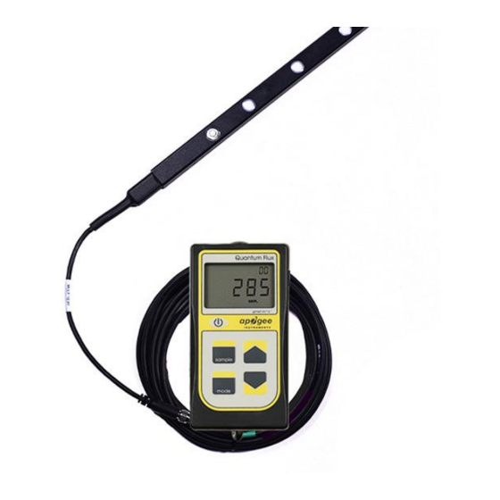
- Page 5 Apogee Instruments MQ-301X line quantum consists of a separated sensor bar with 10 sensors connected to a hand-held meter via cable. The SQ-301X line quantum consists of the sensor bar with 10 sensors and pre-tinned pigtail leads.
-
Page 6: Sensor Models
Line quantum sensors provide spatially averaged PPFD measurements. All sensors along the length of the line are connected in parallel, and as a result, Apogee line quantum meters display PPFD values that are averaged from the location of the individual sensors. -
Page 7: Specifications
SPECIFICATIONS MQ-301X SQ-301X Sensitivity 0.1 mV per µmol m Calibrated Output 0 to 250 mV Range Calibration ± 5 % (see calibration Traceability below) Uncertainty Measurement Less than 0.5 % Repeatability Long-term Drift Less than 2 % per year (Non-stability) Non-linearity Less than 1 % (up to 2500 µmol m Response Time... - Page 8 Spectral Response Mean spectral response of four SQ-100X series quantum sensors compared to PPFD weighting function. Spectral response measurements were made at 10 nm increments across a wavelength range of 350 to 800 nm in a monochromator with an attached electric light source. Measured spectral data from each quantum sensor were normalized by the measured spectral response of the monochromator/electric...
- Page 9 Cosine Response Directional (cosine) response is defined as the measurement error at a specific angle of radiation incidence. Error for Apogee SQ- 100X series quantum sensors is approximately ± 2 % and ± 5 % at solar zenith angles of 45° and 75°, respectively. Mean cosine response of five SQ- 100X series quantum sensors.
-
Page 10: Deployment And Installation
DEPLOYMENT AND INSTALLATION Apogee MQ X series line quantums are designed for spot-check measurements, and calculation of daily light integral (DLI; total number of photons incident on a planar surface over the course of a day) through the built-in logging feature. To accurately measure PFFD incident on a horizontal surface, the sensor bar must be level. Line quantum sensors are leveled using the built-in bubble level located in the handle of the sensor. -
Page 11: Battery Installation And Replacement
BATTERY INSTALLATION AND REPLACEMENT Use a Phillips head screwdriver to remove the screw from the battery cover on the meter. Remove the battery cover by slightly lifting and sliding the outer edge of the cover away from the meter. To power the meter, slide the included battery (CR2320) into the battery holder, after removing the battery door from the meter’s back panel. -
Page 12: Cable Connectors
CABLE CONNECTORS Apogee sensors offer cable connectors to simplify the process of removing sensors from weather stations for calibration (the entire cable does not have to be removed from the station and shipped with the sensor). The ruggedized M8 connectors are rated IP68, made of corrosion-resistant marine-grade stainless-steel, and designed for extended use in harsh environmental conditions. -
Page 13: Operation And Measurement
OPERATION AND MEASUREMENT Connect the sensor to a measurement device (meter, datalogger, controller) capable of measuring and displaying or recording a millivolt signal (an input measurement range of approximately 0-500 mV is required to cover the entire range of PPFD from the sun). In order to maximize measurement resolution and signal-to-noise ratio, the input range of the measurement device should closely match the output range of the quantum sensor. - Page 14 MQ X series line quantum meters are designed with a user-friendly interface allowing quick and easy measurements. Press the power button to activate the LCD display. After two minutes of non-activity the meter will revert to sleep mode and the display will shut off to conserve battery life. Press the mode button to access the main menu, where the appropriate calibration (sunlight or electric light) and manual or automatic logging are selected, and where the meter can be reset.
- Page 15 Review/Download Data: Each of the logged measurements in either SMPL or LOG mode can be reviewed on the LCD display by pressing the up/down buttons. To exit and return to the real-time readings, press the sample button. Note that the integrated daily total values are not accessible through the LCD and can only be viewed by downloading to a computer.
- Page 16 Sensor Calibration The MQ-301X quantum X line sensors have a standard PPFD calibration factor of exactly: 10.0 µmol m per mV Multiply this calibration factor by the measured mV signal to convert sensor output to PPFD in units of µmol m Calibration Factor (10.0 µmol m per mV) * Sensor Output Signal (mV) = PPFD (µmol m 10.0...
- Page 17 Spectral Error Apogee SQ-301X sensors can measure PPFD for sunlight and electric light with a single calibration factor. However, errors occur in various light sources due to changes in spectral output. If the light source spectrum is known, then errors can be estimated and used to adjust the measurements. The weighting function for PPFD is shown in the graph below, along with the spectral response of Apogee MQ-301X series quantum sensors.
- Page 18 The Apogee line quantum has an immersion effect correction factor of 1.15. This correction factor should be multiplied to measurements made underwater. NOTE: The handheld meter portion of the instrument is not waterproof. Do not get the meter wet or leave the meter in high humidity environments for prolonged periods of time.
- Page 19 APOGEE AMS SOFTWARE Downloading data to a computer requires the AC-100 communication cable and the free ApogeeAMS software. The meter outputs data using the UART protocol and requires the AC-100 to convert from UART to USB, so standard USB cables will not work. The most recent version of ApogeeAMS software can be downloaded at http://www.apogeeinstruments.com/downloads/.
- Page 20 “Daily Totals” shows all the saved Daily Light Integral (DLI) totals per day. Click “30 Min Avg” to see the meter’s 99, 30-minute averages. To analyze the data, click on “File” and “Save As” to save the data as a .csv file. Or you can highlight the numbers, copy, and paste them into a blank Excel spreadsheet.
-
Page 21: Maintenance And Recalibration
3. Salt deposit accumulation from evaporation of sea spray or sprinkler irrigation water. Apogee Instruments upward-looking sensors have a domed diffuser and housing for improved self-cleaning from rainfall, but active cleaning may be necessary. Dust or organic deposits are best removed using water, or window cleaner, and a soft cloth or cotton swab. - Page 22 Homepage of the Clear Sky Calculator. Two calculators are available: one for quantum sensors (PPFD) and one for pyranometers (total shortwave radiation). Clear Sky Calculator for quantum sensors. Site data are input in blue cells in middle of page and an estimate of PPFD is returned on right-hand side of page.
-
Page 23: Troubleshooting And Customer Support
TROUBLESHOOTING AND CUSTOMER SUPPORT Verify Functionality Pressing the power button on the meter should activate the LCD and provide a real-time PPFD reading. Direct the sensor head toward a light source and verify the PPFD reading responds. Increase and decrease the distance from the sensor to the light source to verify that the reading changes proportionally (decreasing PPFD with increasing distance and increasing PPFD with decreasing distance). - Page 24 The LCD display will flash all segments and then show a revision number (e.g. “R1.0”). This indicates the master reset was performed and the display should return to normal. Error Codes and Fixes Error codes will appear in place of the real-time reading on the LCD display and will continue to flash until the problem is corrected.
-
Page 25: Return And Warranty Policy
RETURN AND WARRANTY POLICY RETURN POLICY Apogee Instruments will accept returns within 30 days of purchase as long as the product is in new condition (to be determined by Apogee). Returns are subject to a 10 % restocking fee. WARRANTY POLICY... - Page 26 84321, USA 5. Upon receipt, Apogee Instruments will determine the cause of failure. If the product is found to be defective in terms of operation to the published specifications due to a failure of product materials or craftsmanship, Apogee Instruments will repair or replace the items free of charge.
Need help?
Do you have a question about the APOGEE LINE QUANTUM and is the answer not in the manual?
Questions and answers