Table of Contents
Advertisement
Quick Links
Advertisement
Table of Contents

Subscribe to Our Youtube Channel
Related Manuals for Apogee Instruments SI-4HR


Summary of Contents for Apogee Instruments SI-4HR
-
Page 1: Owner's Manual
OWNER’S MANUAL INFRARED RADIOMETER Models SI-4HR Rev: 31-Aug-2022 APOGEE INSTRUMENTS, INC. | 721 WEST 1800 NORTH, LOGAN, UTAH 84321, USA TEL: (435) 792-4700 | FAX: (435) 787-8268 | WEB: APOGEEINSTRUMENTS.COM Copyright © 2022 Apogee Instruments, Inc. -
Page 2: Table Of Contents
TABLE OF CONTENTS Owner’s Manual ....................................1 Declarations of Conformity ..............................3 Introduction ..................................... 5 Sensor Models ..................................6 Specifications ................................... 7 Deployment and Installation ..............................8 Cable Connectors ................................... 10 Operation and Measurement ..............................11 Maintenance and Recalibration ............................. 19 Troubleshooting and Customer Support .......................... -
Page 3: Declarations Of Conformity
RoHS 3 compliant using exemption 6c. Further note that Apogee Instruments does not specifically run any analysis on our raw materials or end products for the presence of these substances, but we rely on the information provided to us by our material suppliers. - Page 4 RoHS 3 compliant using exemption 6c. Further note that Apogee Instruments does not specifically run any analysis on our raw materials or end products for the presence of these substances, but we rely on the information provided to us by our material suppliers.
-
Page 5: Introduction
SDI-12 protocol version 1.3. The SI-4HR-SS infrared radiometer is developed for road weather networks specifically, with a 10° vertical field of view, allowing for remote detection of a narrow and distant target roadway. The rectangular-shaped aperture maximizes the horizontal field of view allowing for a larger integrated measurement without including undesired target areas such as sky or surrounding terrain. -
Page 6: Sensor Models
SENSOR MODELS Model Output SI-400 Series SDI-12 SI-100 Series Voltage A sensor’s model number and serial number are located on a label near the pigtail leads on the sensor cable. If the manufacturing date of a specific sensor is required, please contact Apogee Instruments with the serial number of the sensor. -
Page 7: Specifications
SPECIFICATIONS SI-4HR-SS Input Voltage Requirement 5.5 to 24 V DC Current Drain 1.5 mA (quiescent), 2.0 mA (active) Calibration Uncertainty (-30 to 65 C), when target and 0.3 C detector temperature are within 20 C Calibration Uncertainty (-40 to 80 C), when target and detector temperate are different by more than 20 C 0.5 C... -
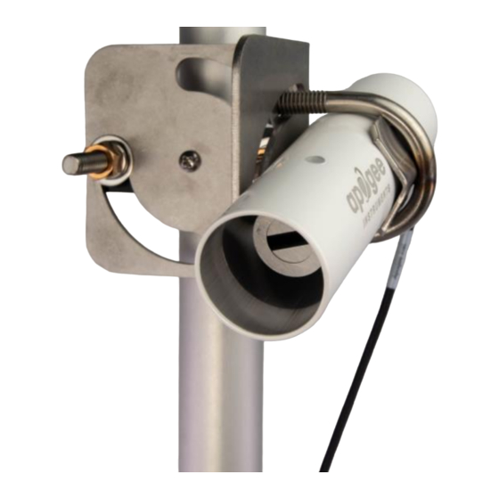
Page 8: Deployment And Installation
An Apogee Instruments model AM-220 mounting bracket is recommended for mounting the sensor to a cross arm or pole. The AM-220 allows adjustment of the angle of the sensor with respect to the target and accommodates... - Page 9 SI-1H1 32° 13° 2.276 7.148 45.512 Narrow SI-121 18° 1.337 4.461 18.865 Narrow SI-4HR 16° 5° 0.403 1.15 3.341 Ultra-Narrow SI-131 14° 0.787 2.447 8.544 A simple FOV calculator for determining target dimensions based on infrared radiometer model, mounting height,...
-
Page 10: Cable Connectors
CABLE CONNECTORS Apogee offers in-line cable connectors on some bare- lead sensors to simplify the process of removing sensors from weather stations for calibration (the entire cable does not have to be removed from the station and shipped with the sensor). The ruggedized M8 connectors are rated IP68, made of corrosion-resistant marine-grade stainless-steel, and designed for extended use in harsh... -
Page 11: Operation And Measurement
All SI-400 series radiometers have an SDI-12 output, where target and detector temperatures are returned in digital format. Measurement of SI-400 series radiometers requires a measurement device with SDI-12 functionality that includes the M or C command. Wiring for SI-4HR-SS White: SDI-12 Data Line Red: Power In (4.5-24 V DC) - Page 12 Sensor Calibration Apogee SI series infrared radiometers are calibrated in a temperature controlled chamber that houses a custom- built blackbody cone (target) for the radiation source. During calibration, infrared radiometers (detectors) are held in a fixture at the opening of the blackbody cone, but are thermally insulated from the cone. Detector and target temperature are controlled independently.
- Page 13 “!”. SDI-12 language supports a variety of commands. Supported commands for the Apogee Instruments SI-400 series infrared radiometers are listed in the following table (“a” is the sensor address. The following ASCII Characters are valid addresses: “0-9” or “A-Z”).
- Page 14 aM3! a0012<cr><If> Returns angle offset from vertical in degrees. (0 degrees if pointed up, 180 degrees if pointed down.) aMC! or aMC0! a0011<cr><lf> Target temperature w/ CRC aMC1! a0012<cr><lf> Target temperature and sensor body temperature w/ CRC aMC2! a0012<cr><If> Target millivolts and sensor body temperature w/CRC aMC3! a0012<cr><If>...
- Page 15 0D0! 0+23.4563+35.1236<cr><lf> 0C2! 000102<cr><If> 0D0! 0+1.0+35.1236<cr><If> 0C3! 000102<cr><If> 0D0! 0+90.2<cr><lf> where 23.4563 is target temperature, 1.0 is target millivolts, and 35.1236 is detector (sensor body) temperature. Change Sensor Address: aAb! The change sensor address command allows the sensor address to be changed. If multiple SDI-12 devices are on the same bus, each device will require a unique SDI-12 address.
- Page 16 Metadata Commands Identify Measurement Commands The Identify Measurement Commands can be used to view the command response without making a measurement. The command response indicates the time it takes to make the measurement and the number of data values that it returns. It works with the Verification Command (aV!), Measurement Commands (aM!, aM1! … aM9!, aMC!, aMC1! …...
- Page 17 a,<SHEF Code>,<units>;<CR><LF> Identify Measurement Parameter Command example: 1IC_001! The Identify Measurement Parameter Command for sensor address 1, C command, data value 1. 1,RW,Watts/meter squared,incoming solar radiation;<CR><LF> The response from sensor address 1, SHEF code RW, units of Watts/meter squared, and additional information of incoming solar radiation.
- Page 18 Emissivity Correction Appropriate correction for surface emissivity is required for accurate surface temperature measurements. The simple (and commonly made) emissivity correction, dividing measured temperature by surface emissivity, is incorrect because it does not account for reflected infrared radiation. The radiation detected by an infrared radiometer includes two components: 1. radiation directly emitted by the target surface, and 2.
-
Page 19: Maintenance And Recalibration
MAINTENANCE AND RECALIBRATION Blocking of the optical path between the target and detector, often due to moisture or debris on the filter, is a common cause of inaccurate measurements. The filter in SI series radiometers is inset in an aperture, but can become partially blocked in four ways: 1. -
Page 20: Troubleshooting And Customer Support
TROUBLESHOOTING AND CUSTOMER SUPPORT Independent Verification of Functionality The simplest way to check sensor functionality is the aM2! command. This command returns detector temperature and detector voltage output. Detector temperature should read very near room temperature. When the aperature of the sensor is covered with aluminum foil, the voltage output should read very near 0 mV. If the sensor does not communicate with the datalogger, use an ammeter to check the current drain. -
Page 21: Return And Warranty Policy
RETURN AND WARRANTY POLICY RETURN POLICY Apogee Instruments will accept returns within 30 days of purchase as long as the product is in new condition (to be determined by Apogee). Returns are subject to a 10 % restocking fee. WARRANTY POLICY... - Page 22 84321, USA 5. Upon receipt, Apogee Instruments will determine the cause of failure. If the product is found to be defective in terms of operation to the published specifications due to a failure of product materials or craftsmanship, Apogee Instruments will repair or replace the items free of charge.
Need help?
Do you have a question about the SI-4HR and is the answer not in the manual?
Questions and answers